Machine vision – indeed human vision too – relies heavily on contrast. The feature(s) being identified need to stand out against any competing candidate features. Otherwise confusion is present. Which means vision either doesn’t work, or isn’t efficient.
While it’s easy to achieve good contrast in certain machine vision applications, sometimes we’re presented with the special challenges of glare. The target object is the same, in the two images below. If the goal is to read the alphanumeric information, which image would you rather pass to your machine vision software?
Courtesy: Advanced Illumination
Courtesy: Advanced Illumination
Techniques to eliminate glare
Glare can arise due to highly reflective surfaces, especially in combination with the direction of the light source relative to the lens and sensor capturing the image. Thankfully there are a number of techniques to eliminate or substantially reduce glare.
Off-axis lighting
For the 1-D bar code reading application illustrated below, moving the light to an off-axis position creates dark field orientation, eliminating the glare. Identical materials but different geometry does the trick!
a. Lighting diagram; b. High-angle light reflects from specular surface; c. Off-axis light improves the image; Courtesy Advanced Illumination
Diverse lights and geometries
Consider another example. In this case we have a titration tray, with multiple wells. Each well has a laser-etched 2-D code.
(a) the titration tray at low resolution, marked up with red outline around 6 wells isolated in high resolution images (b) – (f)
(b) High-angle ring light
(c) Coaxial light
(d) Dark field ring light
(e) Diffuse dome light
(f) Flat diffuse light
In this scenario, both (d) the dark field ring light, and (f) the flat diffuse light, are far superior to the other options, and the flat diffuse light is the winner.
Flat diffuse light function diagram – light is directed downward, and more off-axis than a coaxial illuminator, yet less off-axis contribution than a dome light. Courtesy Advanced Illumination
NOTE: The example above is NOT meant to suggest that flat diffuse light is always the winner. It’s important to understand the characteristics of the surface you are inspecting, and each candidate type of lighting, and the geometric options. And to test!
Guideline
The following diagram is a general guideline, based upon the two most prevalent surface characteristics: (1) Surface flatness and texture, and (2) Surface reflectivity profile
Guide to likely “best approach” based on prevalent surface characteristics – Courtesy Advanced Illumination
Send your samples
Lighting is a complex topic, so we’re happy to help. If you are uncertain which light type to choose and how to configure, we may be able to do some testing for you. Contact us to arrange sending samples to test in our lab, and we can recommend sensor, lensing, lighting, and configuration options.
About you: We want to hear from you! We’ve built our brand on our know-how and like to educate the marketplace on imaging technology topics… What would you like to hear about?… Drop a line to info@1stvision.com with what topics you’d like to know more about.
Kowa LF high-resolution large-format machine vision lenses are engineered for rigorous industrial imaging. With a 46.0mm image circle, these optics are optimized for 4K line scan cameras and large-sensor area scan systems.
Large image circle options up to approximately 43.3mm to 46mm depending on model.
For sensors with pixel sizes from 7.5µm on LF line scan models and 3.1µm on CLS color line scan model.
Very low distortion for web, print, packaging and materials inspection
Manual focus and iris control.
Noteworthy features
Anti-Rattle F-Mount: Ensures the lens stays locked in place to eliminate image shake in vibration-prone installations.
Enhanced Thumb-Screw Retention: Specialized slide mechanisms prevent thumb screws from working loose, yet allow swift lens removal or changeout as needed.
4K-Ready Optics, Multiple Focal Lengths: Designed for 4K line scan and high-resolution imaging, the LF Series is available in 28 mm, 35 mm, and 50 mm focal lengths for a range of applications.
Industrial reliability: The new ruggedized LF prototypes set a new standard for stability and service life, delivering secure imaging performance under the most demanding circumstances.
Lens selection
If you are a seasoned imaging professional, you may know exactly how to choose the optimal lens, from the large range of available lenses.
About you: We want to hear from you! We’ve built our brand on our know-how and like to educate the marketplace on imaging technology topics… What would you like to hear about?… Drop a line to info@1stvision.com with what topics you’d like to know more about.
TDI is based on the concept of accumulating multiple exposures of the same (moving) object, effectively increasing the integration time available to collect incident light. The object motion must be synchronized with the exposures to ensure a crisp image.
Line scan sensors are available for diverse applications – Courtesy Teledyne DALSA
Context
If an object were stationary, and one wasn’t in a hurry, one could just do a longer exposure in order to achieve an ideally saturated image. But the object in question is in fact moving. And it’s a line scan application. Each line exposure is extremely fast, so there’s not much opportunity to accumulate sufficient light into the sensor.
Candidate solutions
Use “faster” sensor that is more sensitive in low light situations? Conceptually plausible but not always available relative to speed of motion and available light.
Introduce artificial light? Usually one already adds concentrated light with line scan, but for challenging applications it may not be sufficient… relative to the speeds one hopes to attain.
Use Time Delay Integration (TDI) to build up final image as composite from multiple exposures carefully synchronized to object’s motion. Key concept: the object is moving anyway, so take advantage of that movement as an opportunity to get multiple “looks” at the same slice of the object. A variation on “when given lemons make lemonade”.
See the video below for an illustrative simulation. The conceptual application is mail processing, where the goal is to read whether a letter is stamped, with which denomination of postage, all while the letter is moving at continuous speed along a conveyor belt, lit only by ambient or low intensity light.
Courtesy Teledyne DALSA
The memory summing of the successive exposures builds the readout image.
Benefits
Speed: You can increase the speed of the target object or inspection web, improving overall throughput. This alone may be a huge competitive advantage.
Lower lighting costs: Get by with just one instead of two lights, and perhaps just a modest light rather than a high-intensity one.
Signal to noise ratio:SNR is improved. Since multiple exposures are summed, useful image signal increases while random noise is reduced. This gives cleaner images and better defect detection.
Tradeoffs
Clearly sufficient synchronization must be achieved for TDI to work effectively. Thankfully the synchronization doesn’t have to be perfect – a TDI device can comfortably tolerate a 2-4% velocity mismatch between inspection web and imager. This is not difficult to achieve using a web-mounted encoder to supply a sync signal to the camera, even with webs that change speed. There are thousands of successful implementations.
For a wide range of line scan products, the the Teledyne DALSA Linea families. For TDI in particular, drill in on the Linea HS and Linea HS2 products.
Applications
Typical applications include, but are not limited to:
Semiconductor wafer inspection
High-density interconnect inspection
Quality control on flat panel displays
Some life science applications
In a nutshell, if it’s “light starved” and line scan, TDI can be the answer.
About you: We want to hear from you! We’ve built our brand on our know-how and like to educate the marketplace on imaging technology topics… What would you like to hear about?… Drop a line to info@1stvision.com with what topics you’d like to know more about.
Optical metrology is an application area within machine vision focused on precise measurement using controlled optics, lighting, cameras, and calibration. Telecentric lenses are designed to maintain constant magnification over a defined depth range, reducing perspective error.
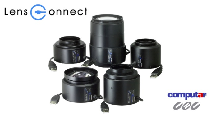
Computar LensConnect telecentric motorized lenses are the first in the industry to combine these features. That brings precision telecentric optics with intelligent remote focus control for high-accuracy industrial imaging and measurement applications.
LensConnect USB powered motorized telecentric lenses – Courtesy Computar
Example application: PCB Inspection
Consider the following application:
Courtesy Computar
The application needs to BOTH measure the height of all three indicated components AND to OCR read/verify/record the markings on the components. That requires both telecentricity and focus control.
Courtesy Computar
Motorized automated focus is key differentiator
In the short 35 second video below, one can see how lens controls are parameterized to automatically optimize focus, adapting to variable conditions.
Four different magnification options
There are 4 different lens models in the series, with magnifications of:
Ideal for metrology, semiconductor, and electronics inspection
Simplifies remote setup and multi-camera calibration systems
1stVision is pleased to have these LensConnect motorized telecentric lenses in our portfolio, along with all the other Computar lenses. Call us at 978-474-0044.
About you: We want to hear from you! We’ve built our brand on our know-how and like to educate the marketplace on imaging technology topics… What would you like to hear about?… Drop a line to info@1stvision.com with what topics you’d like to know more about.
New to the 1stVision portfolio, FLIR Blackfly S are available in compact housed and board-level models, with lossless compression, achieving both high speed and high image quality.
Sony Pregius S and ON Semi CMOS sensors for high sensitivity, low noise image quality
Compact 29 × 29 mm “ice cube” form factor simplifies integration in tight spaces
Wide resolution range (<1 MP to 20+ MP) supports speed or precision optimization
Advanced on-camera image processing include color correction, lossless compression, lens shading correction
Advanced camera controls (sequencer, timers, counters, events) enable precise automation
Develop Once, Deploy Everywhere
With tens of different models of FLIR Blackfly S, cameras, Teledyne Vision Solutions emphasizes “develop once, deploy everywhere”. Since each housed model has the same form factor, varying only by sensor, from < 1MP to > 24MP, the same SDK, software, and interface deploys seamlessly. Whether you want to increase resolution at an existing camera position, or roll out cameras at new positions and new applications, the breadth of this camera series really helps customers scale easily.
Per the video below, board-level cameras can be deployed in diverse configurations, but share the same board dimensions, SDK options, and interfaces.
Video courtesy of Teledyne
Typical Applications
Automated optical inspection (AOI)
Industrial machine vision inspection systems
Robotics guidance and pick-and-place
Electronics and semiconductor inspection
Medical and life sciences imaging
Barcode reading and logistics automation
Embedded vision and OEM integration
Intelligent traffic systems and transportation imaging
Electronics and semiconductor inspection
Food and packaging inspection
Scientific and laboratory imaging
Additional benefits
Lens costs typically low: Thanks to many Blackfly S cameras using Sony Pregius S sensors, small pixel sizes enable high resolution packed into a small sensor. This means lenses can be physically smaller, which saves weight and materials, and typically translates to lower costs.
Reduced lighting requirements: Another benefit of highly-responsive sensors is that ambient light may be all that’s needed. Or less ambitious artificial lighting. Another possible cost advantage.
Synchronize by PTP: For multi-camera applications, often it’s required to synchronize two or more cameras. Precision Time Protocol (PTP) allows that to happen through the camera network cabling, without additional cable costs or complexity management.
Can be used with Sapera LT (Teledyne Dalsa SDK), so if you’re using DALSA Nano and find a model from the FLIR line up, you can make an easy switch.
Series extended – new models
Even if you thought you knew the Blackfly S series, new models joined the family. For example the BFS-PGE-50Y2 is available in both monochrome and color, with Sony AR0521 1/2.5″ CMOS sensor, 2.2 um pixels, and 24 FPS at 5 MP. With a CS-mount it’s ideal for flexible optics choices and system integration.
Call us at 978-474-0044. We can guide you to the optimal sensor, camera, and interface for your application requirements. We’ve also got you covered for lensing, lighting, software, and accessories.
About you: We want to hear from you! We’ve built our brand on our know-how and like to educate the marketplace on imaging technology topics… What would you like to hear about?… Drop a line to info@1stvision.com with what topics you’d like to know more about.
High dynamic range (HDR) isn’t new. It’s frequently mentioned. And offered on-camera, or via software or FPGA. Is it just a marketing term, or a real benefit? If your application’s scenes contain both bright and dark regions, HDR can absolutely deliver benefits.
Consider the three images shown below:
Courtesy JAI
Neither the “slow shutter” image nor the “fast shutter” image is optimal. The former is over-saturated – one can’t even find the many windows in the central building. The fast shutter image is of course too dark, essentially losing the arch and the flagpole. While this scene is more from the realm of “photography” than “machine vision”, the concepts are the same.
Clearly the best image is the HDR image – the lighter areas are revealed in nuanced detail, but so too the unlit trees and gray windows are clear in their own degrees of black and gray, and everything in between. How is this achieved?
What is HDR?
Let’s unpack the acronym, starting with DR for dynamic range. DR is the ratio between the largest and smallest measurable values, for the quantity being measured. For machine vision, it’s light intensity that’s being quantified.
Generally speaking, a larger dynamic range is preferrable to a small one, as the nuanced differences of a relatively larger dynamic range may be required for effective image processing. Take edge-detection, a common machine vision requirement for many applications. The edge may only become apparent, under given lighting conditions and resolution, when the saturation of pixels in a given region are consistently lower to one side and consistently higher to the other side of the “emergent” edge. With sufficient dynamic range, calculated confidence grows, while poor dynamic range may fail to reveal an edge at all.
Ways to create a composite HDR image
One way to create an HDR image is with two exposures and an algorithm for creating the composite. The shorter exposure captures the more brightly lit or highly reflective surfaces, while the remaining regions remain unsaturated or only slightly registering. A longer exposure oversaturates the lighter targets, but reveal nuanced variation in the previously unrevealed details.
In fact one does the longer exposure first, such that the darker portions of the scene produce a variance of non-zero values – i.e. a dynamic range across the darker regions.
Then for the shorter exposure, use the brightest non-saturated pixels from the first exposure as a reference to generate small non-zero values as a control on the short exposure, creating a calculated point of overlap. That way many pixels that were oversaturated on the long exposure are only slightly to moderated saturated on the short-exposure, for a nuanced spread of values across the corresponding pixels.
The blending algorithm compares the two images, pixel for pixel, with the overlap point as a reference. Saturated pixels in the first image are replaced with the corresponding non-saturated pixel values from the second image.
While the two-exposure approach described above is easy to understand, there’s clearly a time-cost in taking two successive exposures, reading them both out to the PC host, and doing the image processing. For certain applications, that may be acceptable. For others, especially with motion involved, or desired high cycle counts, one might hope for a faster approach.
Another way: multi-slope pixel generation on CMOS sensors
The rise of CMOS sensors and their transistor-based pixel architecture enables on-sensor functionality that convenient supports the generation of HDR images. This may be achieved by resetting pixels approaching saturation, prior to end of exposure, so those pixels have an opportunity to be filled from a range of values instead of maxing out had the reset not occurred.
Consider the follow two diagrams, and the supporting discussion below:
If many pixels fill before the end of the exposure, a lot of the image may be oversaturated, even though the darker regions need a longer exposure to become meaningfully non-zero. Courtesy JAI.
But thanks to CMOS transistors at each pixel position, the sensor can be programmed to monitor saturation values, and to reset pixels approaching saturation to “partial fill” levels that allow additional fill for the remainder of the exposure.
Courtesy JAI
It gets even better
Above was “intro level” HDR, concepts and techniques that provide the foundation. Meanwhile innovators keep taking it to the next level.
For example, Sony now offers Quad HDR on their IMX900 sensor, available in the IDS uEye low-cost cameras. Getting the dark sections sufficiently saturated while not oversaturating the brighter regions is really evident with Quad HDR below.
Quad HDR generates a balanced image – Courtesy IDS
In the video below, you may jump to position 1 minute 42 seconds for more on Quad HDR:
Even more on HDR:
If you’d like to read a more in-depth treatment on HDR, including more example images, supporting arithmetic and graphical rational, download our whitepaper on High Dynamic Range Imaging.
Or perhaps you have an application with known nuanced dark regions as well as variation in the saturated areas, for which HDR may add value. Should you do it on-camera/sensor? In an FPGA/frame-grabber? On the PC host? Use lighting techniques to avoid needing HDR altogether? There are a number of different ways to achieve optimal image outcomes, but HDR is certainly a valuable technique for some applications.
Call us at 978-474-0044, and let us guide you to a best-fit solution.
About you: We want to hear from you! We’ve built our brand on our know-how and like to educate the marketplace on imaging technology topics… What would you like to hear about?… Drop a line to info@1stvision.com with what topics you’d like to know more about.
Do you seek a single-device solution for process monitoring – a video streaming/recording industrial camera without needing an additional PC? IDS uEye Live SCP | SLE compact industrial cameras enable monitoring tasks to be executed directly on the camera without the need for an additional PC.
If you need to visualize, document, or monitor processes, this camera is quick to integrate and requires no programming. No PC is needed, as it’s a system on a chip, embedded in the camera.
Just as vehicle dashcams and video doorbells capture sequences that are useful to have documented, it can be useful to capture industrial processing sequences that would otherwise have been missed.
Whether for quality control, process improvement, compliance requirements, or liability, videos of “where it went wrong” can be incredibly valuable. Using the event recording feature, one may have a lookback window of recorded streaming, in order to go back and replay the sequence, extract frames, etc.
Courtesy IDS Imaging
UEye SCP is the housed version:
Courtesy IDS Imaging
It’s also available in space-saving board-level options (shown below), as well as a wash-down IP69K housed version (not shown here):
Courtesy IDS Imaging
Process monitoring
Here’s a video focused on process monitoring applications with IDS uEye Live cameras. It’s the logical follow on video to the introductory video above:
Going further yet – from streaming to AI: scalable process monitoring
It doesn’t have to stop with “simple” industrial dashcam applications – though there’s nothing wrong with stopping there if you are getting good value. This segment goes on to introduce the concept of scaling up your processing monitoring, even to adding AI to interpret and act upon multiple live streams.
This video introduces how IDS industrial monitoring cameras enable scalable, network‑ready process monitoring – from simple streaming to advanced AI‑based analysis. You’ll learn how compressed video streaming, remote access and built‑in intelligence support a wide range of industrial and inspection tasks.
About you: We want to hear from you! We’ve built our brand on our know-how and like to educate the marketplace on imaging technology topics… What would you like to hear about?… Drop a line to info@1stvision.com with what topics you’d like to know more about.
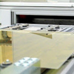
We’ve provided product overviews and updates on Teledyne DALSA’s AxCIS Contact Image Sensor in prior blogs, including a recent one on applications.
AxCIS modules – Courtesy Teledyne DALSA
New models and features
The AxCIS product family now includes color models in widths of 400mm, 600mm, and 800mm. Monochrome models are offered at 400mm and 800mm respectively. In imperial units that spans from 16 – 32 inches.
AxCIS provides selectable 28/42/56/84um pixel size and high speed 50/60/100/120kHzx3 via the Camera Link HS interface.
Lighting flexibility
While sensors and features are always big factors in machine vision, pros know that lighting is just as important. AxCIS’ designers provide users with considerable flexibility on lighting options.
AxCIS modules may be purchased either with or without lighting. The with-lighting option provides tremendous value and ease of deployment – when appropriate for your application.
Here’s a short video showing all that’s bundled into a CIS (including bundled lighting):
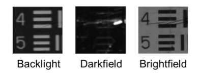
But lighting isn’t one size fits all
The bundled lighting referenced above would be ideal for bright-field illumination. But what if your application is best-served by dark-field lighting, or another approach? To review lighting, see our KB article on lighting techniques.
Since AxCIS modules may also be supplied without bright-field lighting, we offer coax and other lighting solutions suitable for dark field methods.
Lab testing available
If you are uncertain whether this could be your solution, or which components would be optimal, contact us to test your samples in the lab. You can send us parts and we’ll scan them, sending you the results and the optimal device recommendations and configurations. It’s a way to get proof of concept with a lot of the effort outsourced to us.
About you: We want to hear from you! We’ve built our brand on our know-how and like to educate the marketplace on imaging technology topics… What would you like to hear about?… Drop a line to info@1stvision.com with what topics you’d like to know more about.
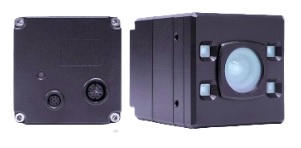
Next level time-of-flight – ToF. Nion combines spatial resolution of 1.2 MP (@30 fps) with reliable depth precision. Housed in a robust IP67 enclosure, Nion captures 3D for even fine structures – cost-efficiently.
Nion 3D ToF camera – Courtesy IDS Imaging
OnSemi AF0130 Hyperlux ID sensor
The AF0130 belongs to the Hyperlux ID family. It’s an Indirect Time of Flight (iToF) sensor, back side illuminated (BSI) CMOS global shutter depth and imaging solution. It calculates depth, confidence and intensity maps at high speeds from its laser modulated exposures.
But while powerful, stereo vision requires at least two cameras, and the corresponding electronics and software to synchronize the images and build the 3D model. So it can be overkill if you don’t need that level of performance.
With the Nion ToF product, IDS brings a more affordable 3D imaging solution to the market, which is more than good enough for many 3D applications .
The video below provides a nice overview. We tease out some of the key points in text and graphics further below, but you might like the dynamics of the video:
What’s inside that IP67 enclosure?
IP67 means dustproof and immersible in water to a depth of 1 meter for up to 30 minutes. That’s pretty robust. More than good enough for even the most challenging industrial environment, outdoor or wash down context.
Besides the tight enclosure, of course there’s a lens to focus the light source onto the sensor, electronics to support the GigE Vision interface, the sensor is the heart of the matter.
Exploded view of Nion camera – Courtesy IDS Imaging
Highest resolution industrial ToF camera
As this blog is released in April 2026, this is the highest resolution industrial ToF camera on the market.
To calculate a single depth value, four coordinated exposures with different phase positions (typically 0°, 90°, 180° and 270°) are usually necessary. These four signals are then used to calculate the phase shift – and thus the distance. Thanks to its special pixel architecture and integrated on-chip processing, the AF0130 iToF sensor captures all four phase images in quick succession and stores them directly and completely in the chip’s memory – without any intermediate readout.
This significantly shortens the time between exposures and noticeably reduces motion blur. Another advantage of continuous reading: The depth information can be efficiently re-sorted and directly processed further – without time-consuming post-processing. This not only makes the camera more robust against movement, but also enables higher frame rates and reduces the load on the host system. This is a decisive advantage, particularly in dynamic applications such as robotics, logistics or pick-and-place.
Courttesy IDS Imaging
Key takeaways on motion artefact reduction are:
Boiling the above section down to key takeaways, we note:
Multi-phase demodulation (four, to be specific)
Reduced motion artefacts in dynamic scences
Suggested Markets
Just to whet the appetite, we call out logistics, robotics, medical, and manufacturing as sectors where affordable ToF 3D imaging can deliver value on investment. But of course you may have 3D applications in mind in another sector.
About you: We want to hear from you! We’ve built our brand on our know-how and like to educate the marketplace on imaging technology topics… What would you like to hear about?… Drop a line to info@1stvision.com with what topics you’d like to know more about.
In machine vision, historically there is a preponderance of fixed focal length (FFL) lenses, also know optically as a prime lens. They are less complex to design and manufacture, and are high-performance in terms of image sharpness and ability to accept wide aperture options for low-light applications. FFL lenses are typically are set for a designed FOV and WD and don’t have flexibility on focal lengths. If your application is like that, lucky you.
But my application isn’t like that!
You may have a factory production monitory project, for example. You know the general dimensions of the layout and the approximate camera mounting position. But you have limited time to configure and deliver proof of concept or acceptance testing. so you want to show up with everything you need to achieve good outcomes, instead of guessing wrong on a fixed focal length lens and having to exchange it.
Whatever your planned application, you know the optical “neighborhood” but need the flexibility to fine-tune in the field.
Zoom lens
A zoom lens remains in focus across a range of focal lengths, and is often remotely controlled. Likewise it’s also often motorized. So they tend to be large(ish), heavier, more complex to design, and are more expensive than a fixed-focal length lens.
Zoom lens at differing optical magnifications – Courtesy Edmund Optics
In the illustration above, notice how the light rays entering from the right range from a wide field of view (FOV) at the top to a narrow FOV at the bottom. That’s a consequence of the changing focal length. It’s an asset if you need that behavior. Or a liability if you don’t
This blog is about varifocal lenses, so that’s all we’ll say about zoom lenses here. But the “different focal lengths” and “different FOV” concepts also apply to varifocal lenses, so it’s worth noting points of overlap.
Varifocal lens
A varifocal lens is designed to hit the sweet spot between fixed focal length vs. zoom. By spanning a (modest) range of focal lengths, a varifocal lens can be adapted in the field to optimize for observed conditions.
You might not know at design time exactly what final focal length you’ll choose, so a range of coverage lets you tune as you deploy and run acceptance tests. It also means the same lens could be used for a year or more in one setting – then loosen a set screw, refocus, and tighten the set screw and the same lens performs great in the new context.
Example: per red ellipses markup, this lens offers focal lengths from 4.4 – 11mm – Courtesy Kowa
But unlike a big motorized zoom, the varifocal lens is often* manually adjusted. And it’s typically modest in size, weight, design complexity, and cost.
(*) EXCEPTION! The Optotune electrically tunable series describe below uses liquid lens technology for autofocus within milliseconds.
Enough concept already – what varifocal lenses are available?
Below we present and link to three different varifocal product lines carried by 1stVision. We sequence by alphabetical order, but each series has its own value proposition, depending on your application needs:
Kowa LMVZ Varifocal Lenses
Kowa’s LMVZ varifocal lenses are designed for machine vision, industrial inspection, and surveillance applications. Their adjustable focal length design allows integrators to fine-tune field of view without changing lenses.
Kowa LMVZ varifocal lenses – optionally with IR correction for VIS + SWIR – Courtesy Kowa
Optotune Focus Tunable Lenses
Optotune is an industry leader in focus tunable lenses. Many are electrically tunable, utilizing liquid lens technology. They also offer a manually tunable lens.
A focus tunable lens – Courtesy Optotune
Unlike manually tunable varifocals, the EL series offers fast, precise autofocus in milliseconds with no moving mechanics.
Tamron Vari-Focal Lens Series
The Tamron vari-focal series is designed for high-resolution IP and security surveillance cameras. These lenses offer flexible focal length adjustment for both wide-area coverage and detailed zoom.
Mega Pixel varifocal lens series – Courtesy Tamron
Select IR-corrected models enable true day/night performance, while compact, durable construction ensures dependable operation in commercial, industrial, and municipal security installations.
Optics is partly physics and science…
But it’s also engineering, and performance requirements, and budget, and experiential knowledge. If you’ve got a lot of all that in your wheelhouse, just call for a quote at 978-474-0044. Or if you’d like some help in choosing, call that same number and tell us a little about your application. Either way, we’re here for you. For lenses, cameras, and more.
About you: We want to hear from you! We’ve built our brand on our know-how and like to educate the marketplace on imaging technology topics… What would you like to hear about?… Drop a line to info@1stvision.com with what topics you’d like to know more about.
uEye EVS Event Based Cameras – Courtesy IDS Imaging
We introduced these event-based cameras in a previous blog – still a great entry point and overview. In this new blog we’ll highlight use cases. They are pretty compelling.
But first we re-run a single graphic to highlight the paradigm shift from frame-based to event-based imaging:
XCP-E Event based cameras utilize the Sony Prophesee sensor – Courtesy IDS Imaging
If you come from a frame-based imaging background – as most of us do – it’s worth getting one’s head wrapped around the event based model. It’s that different – at the technology level and in what it enables at the applications level.
On to use cases and key takeaways…
Results instead of raw data: Per the scene-driven remark in the paradigm comparison graphic above, observe the video analysis clip below. By ONLY picking up on motion, the camera delivers exactly and only what one wants – the people and suitcases passing through the field of view.
Results instead of raw data – Courtesy IDS Imaging
A frame-based approach to such an application would require complex algorithms to identify the “moving stuff” from the “background stuff”, which is compute intensive. It may be doable the hard way, but it takes effort – and isn’t as performant.
Extremely high dynamic range
See in the dark. The Sony Prophesee IMX636 sensor recognizes contrast changes even from 0.08 lux.
Sensitive in very low light – Courtesy IDS Imaging
Detect extremely fast processes
Temporal resolution <100us. i.e. the minimum measurable time difference between two consecutive pixel events, is less than 100µs. That’s comparable to a traditional image-based frame rate of more than 10,000 FPS without motion blur.
High speed applications – Courtesy IDS Imaging
blah blah
Efficient data processing
Only changes are captured – static areas are ignored. So there is (much) less data to process than with a frame-based approach. This saves memory, data transfer volumes, and compute time.
The astute reader will have already inferred that this is a corollary on the “results instead of raw data” message and video earlier in this blog. It’s such a key point it bears repeating.
Less data generated means less data to process – Courtesy IDS Imaging
The following short video shows that the Sony Prophesee IMX636 is the key to sending less data, as it only senses “what’s changed”. Essentially it lights up a pixel exactly and only when that position senses motion – and not when it doesn’t.
Frame-based approach sends entire frame every time vs. event-based just sends each next change – Courtesy IDS Imaging
Use cases
Some of the videos above suggest certain use cases, but let’s spell out a few:
Monitoring: Compared to CCTV, the IDS uEye XCP-E cameras are more compact, and only show action as opposed to (also) steady-state. Or combine the two with event-based cameras logging the timestamps of interest.
Video analysis and Smart City people tracking: A level up from simple monitoring, people tracking doesn’t just detect motion but infers/projects trajectories, and may lead or assist in threat detection.
Drone detection: Just as with people tracking, an event-based camera finds what’s moving against a field of static clutter, as it only sees what’s moving.
Gesture recognition: UI design opportunities, whether for pupil tracking, head motions, and/or hand/finger tracking.
Industrial applications: Monitor equipment vibration to optimize preventative maintenance and/or anticipate and avoid catastrophic breakdown.
Counting: E.g. pill production and sorting, food processing, or other fast-but-small-items conveyor applications.
Takeaway: If it moves, an event-based camera will find it.
See the entire family of IDS uEye XCP-E cameras. Call us at 978-474-0044. Tell us a little about your application and we’ll help you pick the ideal camera and accessories.
About you: We want to hear from you! We’ve built our brand on our know-how and like to educate the marketplace on imaging technology topics… What would you like to hear about?… Drop a line to info@1stvision.com with what topics you’d like to know more about.
Frame grabbers interface between high-speed cameras and PCs to reliably transfer and buffer image data. They can also do various pre-processing and image transformations, improving throughput and reducing workload on the PC.
Teledyne DALSA is a recognized industry leader in frame grabbers and machine vision cameras. Their board-level frame grabbers are dependable and high-performance. Now there’s Teledyne DALSA’s XTIUM3-CLHS PX8 Camera Link HS Frame Grabber. It’s designed for maximum sustained throughput with high-speed image acquisition rates up to 8.6 GB/s and host transfer rates up to 12.5 GB/s.
High speed data transmission
Using CLHS X-protocol, Xtium3-CLHS PX8 achieves over 97% packet efficiency with 64/66-bit encoding. With 7-lane AOC cables, maximum input data rates at cable lengths beyond 30m. Data forwarding enables real-time redistribution of data to up to 12 computers, connecting with other Xtium3-CLHS grabbers via standard AOC cables. Image courtesy Teledyne DALSA.
Optimized performance and compatibility
The Xtium3 series leverages PCIe Gen4 architecture to deliver sustained throughput of 13.2 GB/s directly to host memory, minimizing CPU overhead and accelerating image processing. Its enhanced memory design supports area and line scan, monochrome and color cameras, and offers exceptional performance for Camera Link HS® and CoaXPress® interfaces.
Faster. More efficient. Higher-performance.
Thanks to Moore’s law and industry innovation, machine vision practitioners benefit from electronics components such as cameras, frame grabbers, and computers that outperform their predecessors. If you already use CLHS and prior generation frame grabbers, you may already know you need or want the XTIUM3-CLHS PX8.
Or are you at the design and brainstorming phase?
We’re always happy to provide a product quote, whether for single units or for multiples, of course. But we take pride in assisting our customers by guiding component selection across camera interfaces, sensor selection, lenses, frame grabbers, and more. Call us at 978-474-0044.
XTIUM3 family – more to follow
The XTIUM3 – CLHS PX8 is the first member of the XTIUM3 family, continuing Teledyne DALSA’s commitment to high-performance frame grabber innovation.
About you: We want to hear from you! We’ve built our brand on our know-how and like to educate the marketplace on imaging technology topics… What would you like to hear about?… Drop a line to info@1stvision.com with what topics you’d like to know more about.
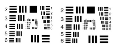
Short Wave Infrared (SWIR) imaging is enjoying double-digit growth rates, thanks to improving technologies and performance, and innovative applications. Unlike visible-light sensors, SWIR cameras can image through silicon, plastics, and other semitransparent materials. That’s really effective for many quality control applications, materials sorting and inspection, crop management, fruit sorting, medical applications, and more.
Visible vs. SWIR image pairs – Courtesy Allied Vision – a TKH Vision brand
Unlike CMOS sensors, from which high-quality images are reliably derived under wide operating conditions, SWIR sensors typically need “tuning” relative to temperature and exposure duration. First generation SWIR cameras sometimes generated images that while useful, were a bit rough and with certain limitations in the extreme. SWIR camera manufacturers have been innovating solutions to raise the performance of their cameras.
What’s the problem?
In short-wave infrared (SWIR) imaging applications, camera operation points such as exposure time, gain and bit-depth need to be adapted depending on the inspection task at hand. Image sensor defects such as defective pixels and image non-uniformities – inherent to SWIR sensors – are sensitive to the aforementioned operations points.
Unless controlled, image quality can suffer
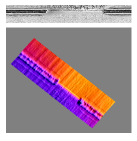
Consider the following image:
The gray field is intentionally unexciting as a flat field baseline without a target. The white dots are undesired defect pixels, an unfortunate characteristic that one can thankfully correct through interpolation. This image is meant to show “what we do NOT want”.
The four parameters exposure setting, temperature, bit-depth, and gain may collectively be called the “Operating Point” of a SWIR sensor, as together they have a significant bearing on image quality. Through manual or automated adjustments, one can optimize image outcomes.
Harnessing variable parameters into manageable corrections – Courtesy Allied Vision – a TKH Vision brand
In this blog, we provide context for these concepts. And we introduce Dynamic Operating Point Optimization (DOPO) as an automated innovation available in the fx series of SWIR cameras offered by SVS Vistek / Allied Vision.
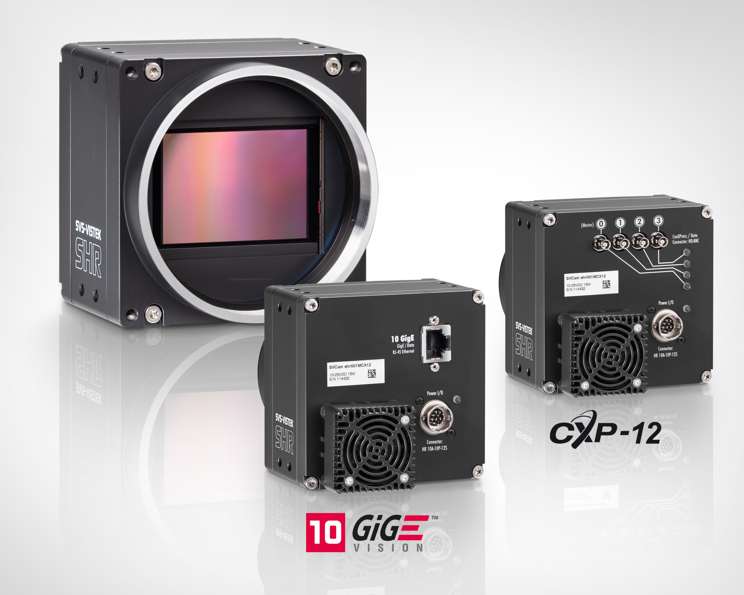
fx series SWIR cameras – Courtesy SVS Vistek / Allied Vision – a TKH Vision brand
Before Dynamic Operating Point Optimization (DOPO)
SWIR cameras with some image correction capabilities – prior to DOPO we’ll describe in the next section – certainly improved image quality. Largely via defect pixel correction (DPC) and non-uniformity correction (NUC).
Defect pixel correction (DPC) is achieved by replacing the “hot” or “dead” pixel value by the average value of its nearest neighbors. As long as there isn’t a cluster defect with multiple adjacent defect pixels (typically identified and rejected at manufacturing quality control), this is an effective solution.
Non-uniformity correction (NUC) is a bit more complex, but worth understanding. The non-uniformities arise in thermal imaging due to variations in sensitivity among pixels. If uncorrected, the target image could be negatively impacted with striations, ghost images, flecks, etc.
Factory configuration of each camera, before finalizing testing and shipping, adapts for the nuanced differences among individual sensors. Correction tables are created and stored onboard the camera, so that the user receives a camera that already compensates for the variations.
In reality it’s a bit more complicated
In fact defect pixels aren’t always simply hot or dead: they may appear only at certain operating points (exposure duration, temperature, gain, bit-depth, or combinations thereof).
Likewise for non-uniformity characteristics.
So that factory configuration mentioned above, while satisfactory for many applications, is a one size fits all best hope compromise, relative to the tools (then) available to the camera manufacturer and the price point the market would accept. Just as with t-shirts and socks, one size doesn’t really fit every need.
Dynamic Operating Point Optimization (DOPO)
Allied Vision has introduced dynamic operating point optimization (DOPO) to further automate SWIR cameras’ capacity to adapt to changes brought about by exposure time, temperature, gain, and bit depth. Let’s examine the graphic below to understand DOPO and the added value it delivers.
First consider the Y-axis, “Image Quality”. Looking at the flat-field gray block, clearly one would prefer the artifact-free characteristics of the upper region.
Also note the X-axis, “Sensor Temperature / Exposure Time”, for an uncooled thermal sensor. (Note that some thermal cameras do have sensor cooling options, but that’s a topic for another blog.) See the black line “No correction” sloping from upper left to lower right, and how the number of image artifacts grows markedly with exposure time. Without correction the defect pixels and sensor non-uniformities are very apparent.
Flat-field image quality with and without corrections – Courtesy Allied Vision – a TKH Vision brand
Now look at the gray lines labeled “NUC+DPC”. For a factory calibrated camera optimized for a sensor at 30 degrees Celsius and a 25ms exposure, the NUC and DPC corrections indeed optimize the image effectively – right at that particular operating point. And it’s “not bad” for exposure times of 20ms or 15ms to the left, or 30ms or 35ms to the right. But the corrections are less effective the further one gets away from that calibration point.
Finally let’s look at the zig-zag red lines labeled “DOPO”. Instead of the “one size best-guess” factory calibration, represented by the grey lines, a DOPO equipped camera is factory calibrated at up to 600 correction maps, varying each of exposure time, temperature, gain and bit depth across a range of steps, and building maps that represent all the stepwise permutations.
Takeaway: DOPO provides a set of correction tables not just one
So with DOPO providing a set of correction tables, the camera can automatically apply the best-fit correction for whatever operating point is in use. That’s the key point of DOPO. Unlike single-fit correction tables, with so many calibrated corrections under DOPO, the best-fit isn’t far off.
Give us some brief idea of your application and we will contact you to discuss camera options.
Thermal imaging with SWIR cameras – plenty of choices
There are a number of options as one selects a SWIR camera. Is your choice driven mostly by performance under extreme conditions? Size? Cost? A combination of these?
Call us at 978-474-0044. We can guide you to a best-fit solution, according to your requirements.
The key message of this blog is to introduce Dynamic Operating Point Optimization – DOPO – as a set of factory calibration tables and the camera’s ability to switch amongst them. An equally important takeaway is that you may or may not need DOPO for a particular thermal imaging application. There are many SWIR options, in cameras and lenses, and we can help you choose.
About you: We want to hear from you! We’ve built our brand on our know-how and like to educate the marketplace on imaging technology topics… What would you like to hear about?… Drop a line to info@1stvision.com with what topics you’d like to know more about.
All of us machine vision practitioners know a thing or two about camera lenses. Some of us are optical engineers. Others are self-taught through reading and experience. Others let their systems designers choose the lens.
Ever need a fast focus change?
If your application does fine with a fixed focal lens, or a mechanically adjustable focus, that’s great. But some applications benefit from – or only become possible with – the ability to rapidly tune the focus. Enter liquid lenses, like Opto Engineering’s EL5MP and EL12MP.
EL5MP liquid lens – Courtesy Opto Engineering
Liquid lenses – from theory to commercial availability
Leonhard Euler (Euler’s equations, anyone?) did groundbreaking work in fluid dynamics in the 1700s. In 1859 Thomas Sutton used a glass sphere filled with water to create a lens. So the concepts for liquid lenses aren’t new. But they’ve only been commercialized in the last 20 years. Here’s a short video (3 minutes) featuring an early leader in liquid lenses, with a nice overview of the key concepts:
From theory to practice – a 5MP and 12MP liquid lens series
If you need fast focus (a few milliseconds) and high reliability (more than a billion cycle lifetime), Opto Engineering offers both a 5MP liquid lens series as well as a 12MP series. Each series provides several focal length options:
6mm for the 5MP series only
8mm for the 5MP series only
12mm for BOTH the 5MP and 12MP series
16mm for BOTH the 5MP and 12MP series
25mm for BOTH the 5MP and 12MP series
35mm for 12MP series only
Working distance coverage range
Across the two series, there are working distances on the near side from 60 – 200mm, depending on the specific model. At the far side the WD goes to infinity for each of the lenses. See the product comparison tables and data sheets at Opto Engineering EL5MP and EL12MP respectively.
More specs
The 5MP series is designed for sensors up to 2/3″. One exception: the 6mm focal length model is for sensors up to 1/1.8″.
The 12MP series is for sensors up to 1.1″.
Basis for liquid lens – Courtesy Opto Engineering
Liquid lens advantages vs. mechanical focus – Courtesy Opto Engineering
Low distortion is another advantage
Liquid lens image (left) has almost no distortion – another huge benefit – Courtesy Opto Engineering
What are the focus demands of your application?
Do you know your application’s focus requirements? Could you build a more effective application with faster focus? Reduce lens service and replacement intervals by switching from a mechanical to a liquid lens? Call us at 978-474-0044 to discuss options or get a quote.
Video presentation on Opto Engineering liquid lenses
Tradeshow presentation runs 14 minutes, if you want to do a deeper dive that way:
Courtesy Opto Engineering
Note: Over the years, various operating principles for liquid lenses have been introduced.
About you: We want to hear from you! We’ve built our brand on our know-how and like to educate the marketplace on imaging technology topics… What would you like to hear about?… Drop a line to info@1stvision.com with what topics you’d like to know more about.
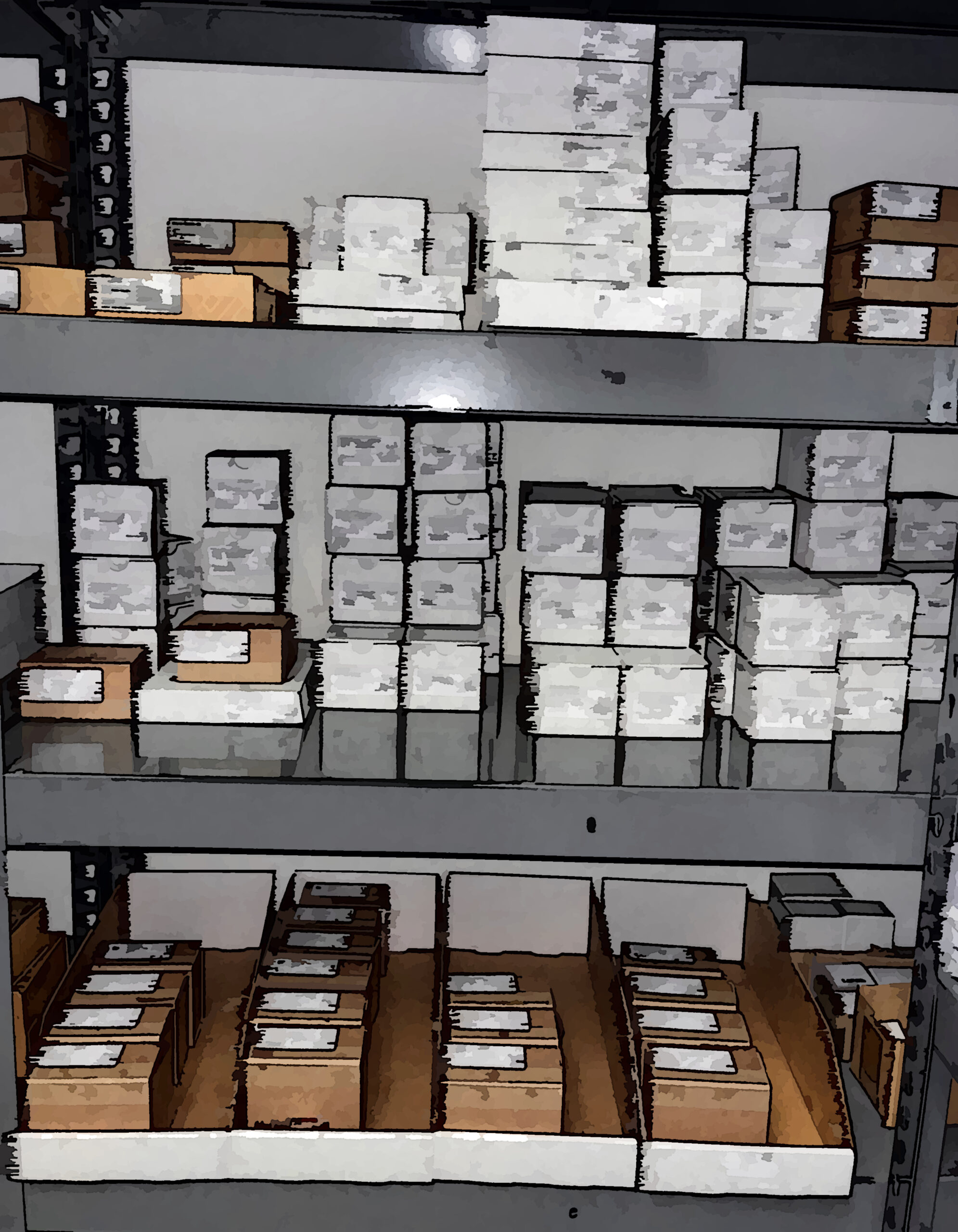
Whether you are new to applying imaging to logistics, or looking to upgrade current systems, 3D machine vision continues to drive innovation and opportunities.
Materials handling in a warehouse – Courtesy IDS Imaging
accurate depth perception helps robots identify and locate items in bulk containers
(De-) Palletizing automation
3D vision supports robot arms in stacking and unstacking pallets
Loading / Unloading trucks
3D object localization improves automation
Some popular logistics tasks supported by 3D imaging
Application areas
Detect and recognize
Bin picking
De-palletizing
Detect and recognize
The ability to accurately detect moving objects to select, sort, verify, steer, or count can enhance (or create new) applications. Ensenso C’s high-luminance projector enables high pattern contrast for single-shot images. Video courtesy of IDS Imaging.
Bin picking
Regardless of a robot’s gripping sensitivity, speed, and range of motion, 3D imaging accuracy is central to success. Ensenso C’s integrated RGB sensor can make all the difference for color-dependent applications. Video courtesy of IDS Imaging.
De-palletize
De-palletizing might seem like a straightforward operation, but must detect object size, rotation and position even with different and densely stacked goods. Ensenso supports all those requirements – even from a distance. Video courtesy of IDS Imaging.
How does stereo imaging work?
Two-eyed humans and other animals, as well as two-camera stereo systems, use triangulation to achieve depth perception. If a given point on an object’s surface is offset more from one sensor than another, the collection of all such measurements can be used to create a point cloud model of the 3D scene.
Note the differential offsets for the projection beams of two cones – Courtesy IDS Imaging
IDS Imaging Ensenso 3D cameras and camera systems are built for industrial 3D imaging with a GigE interface for ease of setup. There are monochrome and color options, as well as hybrid/blended systems. Short-distance capabilities to a few millimeters. Long-distance systems with WD to 5 meters. Modular pre-housed systems. And ruggedized systems for harsh environments.
Ensenso product family – Courtesy IDS Imaging
Short distance applications – Courtesy IDS Imaging
Ensenso XR with working distance to 5m – Courtesy IDS Imaging
Want some help with your logistics systems planning?
Call us at 978-474-0044. Our sales engineers come from diverse machine vision backgrounds, and we stake our reputation on helping clients select the best components and systems.
About you: We want to hear from you! We’ve built our brand on our know-how and like to educate the marketplace on imaging technology topics… What would you like to hear about?… Drop a line to info@1stvision.com with what topics you’d like to know more about.
Event-based cameras outperform frame-based approaches for many applications. We provided insight to the event-based paradigm in a recent blog. Or download our whitepaper on event-based sensing.
In this piece, we focus on drone detection, a task at which event-based imaging excels. For full-impact, please view the following in full-screen mode using the “four corners” button.
Find the drone – Event-based approach beats frame-based method – Courtesy scientific paper attribution
As discussed in the event-based paradigm introductions links above, frame-based approaches would struggle to track a drone moving in a visually complex environment (above left), having to parse for drone shapes and orientations, occlusions, etc., even when most of the imagery is static.
Meanwhile, as seen in the event-based video (above right), the new paradigm only looks for “what’s changed”, which amounts to showing “what’s moving?”. For drone detection, as well as other perimeter intrusion applications, vibration monitoring, etc., that’s ideal.
For some applications, one only needs an event-based sensor – problem solved. For other applications, one might combine different imaging approaches. Consider the juxtaposition of three methods shown below:
Visible, polarization, and event-based approaches – Courtesy Prophesee and EOPTIC
The multimodal approach above is utilized in a proprietary system developed by EOPTIC, in which visible, polarization, and event-based sensors are integrated. For certain applications one may require the best of speed, detail, and situational awareness, for automated “confidence” and accuracy, for example.
Here’s another side-by-side video on drone detection and tracking:
Visible vs. (hybrid) event-based imaging – Courtesy Prophesee and NEUROBUS
The above-left video uses conventional frame-based imaging, where it’s pretty hard to see the drone until it rises above the trees. But the event-based approach used by Prophesee’s customer Neurobus, together with their own neuromorphic technologies, identifies the drone event amidst the trees – a level of early warning that could make all the difference.
By the numbers:
Enough with the videos – looks compelling but can you quantify Prophesee event-based sensors for me please?
Quantifying key attributes – Courtesy Prophesee
Ready to evaluate event-based vision in your application?
1stVision offers Prophesee Metavision® evaluation kits designed to help engineers and developers quickly assess event-based sensing for high-speed motion detection, drone tracking, robotics, and other dynamic vision applications. Each kit provides everything needed to get started with Prophesee’s Metavision technology, including hardware, software tools, and technical support from our experienced machine vision team. Request a quote to discuss kit availability, configuration options, and how we can help accelerate your proof-of-concept or system deployment.” – we can link that page with the kits.
Technical note: The GenX320 Starter kit for Raspberry Pi 5” utilizes the Sony IMX636 sensor, expressly designed for event-based sensing.
Kit or camera? You choose.
The kits described and linked above are ideal for those pursuing embedded designs. If you prefer a full camera – still very compact at less than 5cm per side – and you want a USB3 interface – see IDS uEye event-based cameras. You’ve got options.
About you: We want to hear from you! We’ve built our brand on our know-how and like to educate the marketplace on imaging technology topics… What would you like to hear about?… Drop a line to info@1stvision.com with what topics you’d like to know more about.
Here are some cool new features. At least they’re cool if you already use AVT Alvium cameras and want to get even more out of them. Conversely the features may get your attention to give Alvium a look for your next application.
We call out five specific new features (or feature sets):
Liquid lens autofocus controls – great for logistics applications: fast focus change
Power saving standby mode – heat minimization for embedded designs
Improved recovery from over-temperature power savings mode – automated recovery
More GenICam features for V4L2 Video for Linux – great to have Linux options
Additional registers and controls – if some DRA is good, more is better
Alvium USB3, MIPI CSI-2, 1 GigE and 5 GigE compact and powerful cameras – Courtesy AVT – a TKH brand
Call us at 978-474-0044 to speak to one of our experienced sales engineers. Or tell us what you’d like to know more about – whether concepts, features, or pricing – and we’ll get back to you:
Give us some brief idea of your application and we will contact you to discuss camera options.
Liquid Lens Autofocus Controls
If you’re new to liquid lenses, see our prior blog for examples and an overview. Liquid lenses can change focus within milliseconds, far faster than mechanical apertures.
Below you can see the hardware configuration, which new new autofocus controls can utilize.
Courtesy AVT – a TKH Vision brand
So AVT provides the lens controlling capability on the camera side, and you can optionally connect a liquid lens if that would help your application. Naturally AVT Alvium cameras may also be used with conventional lenses, including S, CS, C, closed, open, and bare-board – range of options varies slightly by model. Please review when ordering or confer with us per adage “measure twice cut once”.
Power saving standby mode
There are at least to reasons why you might be interested in power savings. The layman’s view might be to preserve the environment or save on energy costs. But compact sensors and cameras don’t use a lot of power, often just +/- 1 watt. The primary motivator, for embedded systems designers, is to reduce heat, during periods when no imaging is required. That in turn enhances image quality and prolongs system life.
Power saving mode enabled vs. disabled – Courtesy AVT – a TKH Vision brand
Improved Recovery from over temperature mode
When the camera goes into over temperature mode, it automatically stops power draw as a self-protection mechanism. In firmware V13 this required a camera reboot to resume imaging. Now in V15 the camera resumes normal function without requiring reboot.
Improved recovery from over temperature mode – Courtesy AVT – a TKH Vision brand
(More) GenICam features for V4L2 Video for Linux
If you favor video for Linux (V4L2) drivers and APIs for your development and production controls, below see GenICam features now available to you.
Courtesy AVT – a TKH Vision brand
Additional Registers and Controls
In addition to all the registers previously available on Alvium’s MIPI CSI-2 cameras, below are a number of new registers, whose names suggest their meaning and use. One may control each feature through any of GenICam APIs, V4L2 Video for Linux, or by Direct Register Access (DRA) memory addressing. Whichever method you prefer.
New registers available for DRA – Courtesy AVT – a TKH Vision brand
Manuals for all AVT cameras and SDKs are downloadable, of course. Drill in on any feature or attribute of interest.
About you: We want to hear from you! We’ve built our brand on our know-how and like to educate the marketplace on imaging technology topics… What would you like to hear about?… Drop a line to info@1stvision.com with what topics you’d like to know more about.
If monochrome sensors and methods aren’t enough for your application, a machine vision color camera may be needed. And if color is needed, is “good enough” from a single sensor with a Bayer filter all you need? Or do you need the precision of a prism-based 3 sensor camera, one for each of R, G, and B? See our whitepaper Considerations for Color Machine Vision Cameras.
Prism-based 3-sensor imaging vs. interpolated Bayer mosaic sensors
Bryce Bayer, the engineer at Eastman Kodak whose name is associated with his Bayer filter innovation, created a very compact and efficient way to layer a color filter atop a monochrome sensor. The vast majority of today’s color cameras – in both machine vision and consumer imaging – utilize precisely such a color filter mechanism to interpolate color. When the resolution is sufficiently fine, the rendered image is typically good enough for many applications.
But “good enough” for some isn’t the same as good enough for all
Interpolation is a form of estimation – in the case of a Bayer filter its design presumes that the Red, Green, and Blue values between each of the “true” measurements of those values is the average of the values at the accurate points. So the in-between values are computed, and may or may not correlate to the true color present at the source.
For certain machine vision, industrial imaging, and medical applications, maximum color accuracy is essential.
What’s best for my application?
Read on, for more detail. Or give us a call at 978-474-0044. Or tell us about your requirements and we’ll contact you.
For certain applications, color accuracy and fidelity is essential
Applications note provides further information – Courtesy JAI
All four images and and associated texts above – Courtesy JAI
JAI adds 3 new 5.1 Mpix cameras to its Apex Series
5.1 Megapixel prism-based 3 sensor camera – Courtesy JAI
Previously JAI’s Apex prism-based camera series included 1.6 Mpix and 3.2 Mpix models. Three new models join the series, at 5.1 Megapixels each. The new members all use the same SONY IMX548, one of the Pregius S sensors.
If the new 5.1 Mpix models all use the same sensors, why are there three models? Because there are three interface options, depending on your need for speed.
5 GigE model: 32 fps
CoaXpress model: 75 fps
Camera Link model: 55 fps
Numerous features and benefits
There are many features designed into the Apex series cameras, including binning, single and multi-region ROI, chromatic aberration correction, and automatic level control. Download a manual for details. Or call us at 978-474-0044.
Feature highlight: Per-channel exposure control
Since the rationale for a 3 sensor prism camera is color performance, the per-channel exposure control feature helps to achieve that goal. By adjusting the exposure time for each channel separately, the camera increases signal without amplifying noise.
Per-channel exposure control – Courtesy JAI
Call us at 978-474-0044 to learn more about JAI Apex cameras. Tell us about your application goals and requirements, and we’ll help you determine the best camera, lens, lighting, filters, and software. It’s what we do.
About you: We want to hear from you! We’ve built our brand on our know-how and like to educate the marketplace on imaging technology topics… What would you like to hear about?… Drop a line to info@1stvision.com with what topics you’d like to know more about.
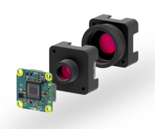
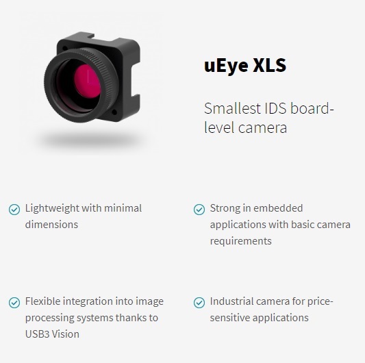
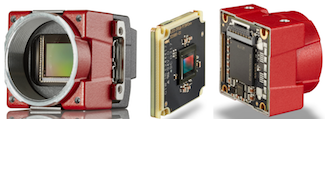
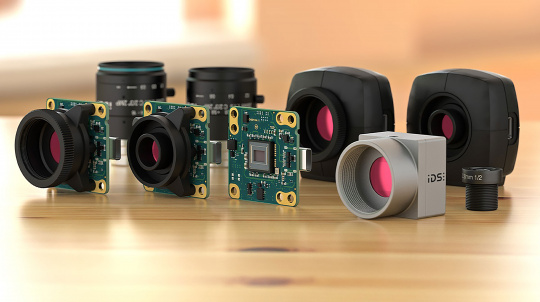
Small housings and powerful sensors didn’t used to appear together. But thanks to ever more compact electronics, and good engineering, one can have both. IDS has expanded its portfolio by integrating the Sony Pregius IMX900 sensor into selected models of the compact USB3 uEye XCP, XLS and GigEuEye LE series.
uEye low cost cameras with Sony Pregius IMX900 sensor – Courtesy IDS
The photo above provides an at-a-glance overview of the various board-level, housing, and lens-mount options, each of which is classified as low cost and very compact.
If you prefer a tabular view like the following, with clickable links to specs and the option to request a quote, go to 1stVision’s cameras page, and scroll down to the selector page with drop-down filters, at https://www.1stvision.com/cameras/industrialCameras
The image below is an annotated screenshot, where the manufacturer (IDS) and the sensor (Sony IMX900) bring you to the 10 distinct camera models utilizing this sensor.
Sony’s Pregius sensor evolution
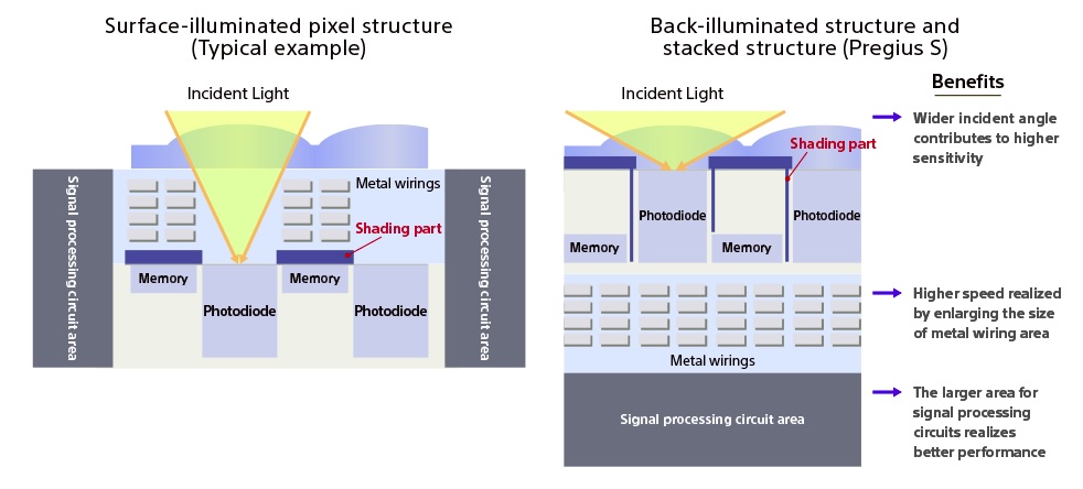
Sony is an industry leader with its Pregious sensor series, on which we’ve written previously with an overview. The Sony IMX900 is in the Pregious S 4th generation, extraordinarily sensitive thanks to Sony innovations including the back-illuminated stacked architecture.
Back-illumination improves sensor quantum efficiency – Courtesy IDS and Sony
VIS plus NIR sensitivity
We won’t bother showing VIS images in monochrome or color but of course they look great. But calling out a special capability of the Sony IMX900 – it’s also very sensitive to near infrared (NIR). Besides being part of the Pregious group, the IMX900 utilized STARVIS 2 technology, yielding NIR performance.
Yet another Sony IMX900 feature: Quad HDR
While high dynamic range (HDR) features aren’t new per se, Quad HDR on the Sony IMX900 takes HDR to another level. Getting the dark sections sufficiently saturated while not oversaturating the brighter regions is really evident with Quad HDR below.
Quad HDR generates a balanced image – Courtesy IDS
The feature list goes on and on
Call us at 978-474-4000 to learn more about this remarkable sensor and the range of IDS uEye cameras into which the sensor has been designed.
About you: We want to hear from you! We’ve built our brand on our know-how and like to educate the marketplace on imaging technology topics… What would you like to hear about?… Drop a line to info@1stvision.com with what topics you’d like to know more about.
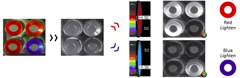
While we humans can only see what we’ve named to be visible light, bees can see UV light! Some camera sensors register IR wavelengths! Some cameras can sense both visible light and on through NIR and SWIR.
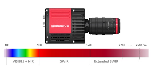
In this piece we focus on applications that benefit from combined VIS-SWIR solutions, from 400 nm through 2.5 nm.
Deconstructing the electromagnetic spectrum into it’s commonly known constituent regions
Example applications
Just to whet the appetite, consider the 4 sets of image pairs below. In each case, the leftmost image was captured with visible wavelengths, while the righthand image utilized SWIR portions of the spectrum. These pairs were chosen to highlight the compelling power of SWIR to identify features that are not apparent in the visible portion of the spectrum.
VIS-SWIR image pairs – Courtesy Allied Vision – a TKH company
For certain applications, one wouldn’t need the human-visible images, of course, as with machine vision the whole point is to automate the image processing and corresponding actions. So for counterfeit banknote detection, bottle fill level monitoring, materials identification, or crop monitoring, one might just design for the SWIR portion of the spectrum and ignore the VIS.
Vein imaging application overlays SWIR image of veins into visible image of patient forearm –Image courtesy TAMRON
But some applications might benefit from both the VIS and the SWIR images. For example, the vein imaging application might require a VIS reference image as well as a SWIR-specific image, for patient education and/or medical records.
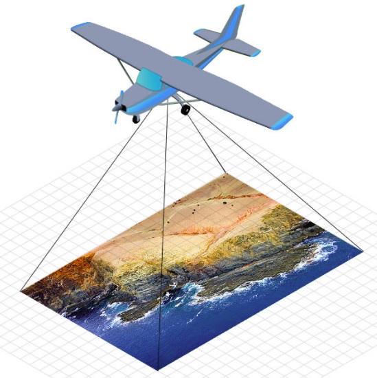
Monitor moisture levels in crops from airborne drone – Image courtesy TAMRON
For the crop monitoring application above, the VIS spectrum clearly orients trees, hills, buildings, and roadways. Meanwhile pseudo-color-mapping shows the varied moisture levels as sensed in the SWIR portion of the spectrum.
The range of potential applications combining VIS and SWIR is staggering. One can improved on one’s own or a competitor’s previous application. Or innovate something altogether new.
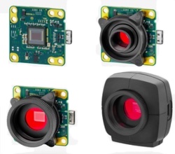
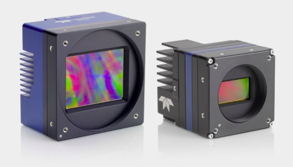
Sensors that register both VIS and SWIR wavelengths
Sony’s IMX992 and IMX993 sensors utilize Sony’s SenSWIR technology, such that a single sensor and camera may be deployed across the combined VIS and SWIR portions of the spectrum. Without such sensors, a VIS SWIR solution would require at least two separate cameras – one each for VIS and SWIR, respectively. That would add unnecessary expense, takes up more space, and require camera and image synchronization.
Now there are cameras, such as several in Allied Vision’s Alvium series, in which Sony’s SenSWIR sensors are embedded. With several interface options, including mipi, USB3 Vision, and 5GigE Vision:
Mipi, USB3 Vision, and 5GigE Vision interface options – Courtesy Allied Vision – a TKH Company
Lens manufacturers doing their part
One of the beauties of the free-market system, together with agreements on standards for interfaces and lens mounts, is that each innovator and manufacturer can focus on what he does best. Sensor manufacturers bring out new sensors. Camera designers embed those sensors and provide programming controls, communications interfaces, and lens mounts. And optics professionals design and produce lenses. The benefits from a range of choices, performance options, and price points.
Navitar VIS-SWIR lenses
Navitar’s ZOOM 7000-2 macro lens imaging system delivers superb optical performance and image quality for visible and SWIR imaging. Their robust design ensures reliability even in harsh environments. ZOOM 7000-2 macro lenses are ideal for applications, such as machine vision, scientific and medical imaging applications.
ZOOM 7000-2 VIS-SWIR lens – Courtesy Navitar
In fact there are three models in the series:
Each model has its application – but only the middle one is designed explicitly for VIS-SWIR – Courtesy Navitar
Kowa FC24M multispectral lenses
Kowa’s FC24M C-mount lens series are manufactured with wide-band multi-coating. That minimizes flare and ghosting from VIS through NIR. These lenses are also compelling for a number of other reasons, including wide working range (as close as 15 cm MOD), durable construction, and a unique close distance aberration compensation mechanism.
FC24M C-mount lens series – Courtesy Kowa
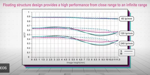
That “floating feature” creates stable optical performance at various working distances. Internal lens groups move independently of each other, which optimizes alignment compared to traditional lens design.
Tamron Wide-band SWIR lenses
Other lensing options include Tamron’s Wide-band SWIR lenses. While the name says SWIR, in fact they are VIS-SWIR. Designed for compatibility with Sony’s IMX990 and IMX991 SenSWIR sensors, you have even more lens choices. Call us at 978-474-0044 if you’d like us to help you navigate to best-fit components in cameras, lensing, and lighting, for your particular application.
About you: We want to hear from you! We’ve built our brand on our know-how and like to educate the marketplace on imaging technology topics… What would you like to hear about?… Drop a line to info@1stvision.com with what topics you’d like to know more about.
Kowa HC-V 1″ C-mount industrial lenses feature a patented design that ensures dependable performance, and consistently clear, crisp images with uniform brightness across the entire image, including the corners. These ruggedized lenses are built for use in harsh environments to withstand strong vibrations and impacts.
Interchangeable iris plates and a two-way reversible nut enable precise focus adjustments, and glued inner glass elements ensure stability. HC-V lenses are compatible with 1″ format sensors including Sony IMX174, CMOSIS CMV4000, and Sony IMX249 sensors. Designed for sensors with a pixel size as small as 5.0μm.
Or for expert assistance just call us at 978-474-0044.
Interchangeable iris plates
The HC-V patented design includes interchangeable iris plates. Secured by a lock nut, this insures precise focus that’s vibration resistant. Ideal for rugged industrial environments.
HC-V ruggedized lens series overview – Courtesy Kowa
How to change the iris plates
How to change the iris plates – Courtesy Kowa
Happy to help
We’re pleased to distribute Kowa lenses, and to advise customers on all aspects of machine vision component selection. Whether for sensor, camera, lens, lighting, software, or other components, tell us about your application, and we’ll be happy to guide you to optimal choices. By phone we’re at 978-474-0044, or key in a few application notes below and we’ll reach out to you at your convenience.
About you: We want to hear from you! We’ve built our brand on our know-how and like to educate the marketplace on imaging technology topics… What would you like to hear about?… Drop a line to info@1stvision.com with what topics you’d like to know more about.
Event-based vision (EBV) is really taking off. We provide an overview of the concepts and applications, as well as Prophesee products for EBV. So here’s a reminder diagram and short video for context, then we’ll dig into using Prophesee EBV kits with Raspberry Pi.
Event-based vision is a new paradigm – Courtesy Prophesee
Frame-based vs. Event-based approach to eye tracking – for example:
So I want to try a Prophesee Metavision Evaluation Kit!
1st vision is the official partner for Prophesee in the US, so start with a quote and purchase a Raspberry Pi 5 CSI modules with the 320×320 pixel GenX320 sensor. Or the GenX320 Raspberry Pi 5 Module.
The main difference between the two are that the M12 lens mount allows for changing lenses yourself, but if you prefer the M6 lens version, you receive a smaller front of the camera and a wider field of view. You can see the variations here: https://www.1stvision.com/cameras/GenX320-Starter-Kit-for-Rasberry-Pi-5
You’ll need to purchase the Raspberry Pi elsewhere, as 1st vision does not sell them.
Prophesee recommends the 8gb vision at a minimum, with the 16 recommended for on board vision computation.
Prophesee also recommends getting the active cooler, 27 W Power supply and NVME adapter.
A further note, the Metavision 5 SDK will not run on the Raspberry Pi 5, as the CPU power is insufficient for that computational load. You’ll need to use the Metavision 4 OpenEB SDK. So to be clear, the SDK choices are:
SDK for Raspberry Pi
SDK for PC
Metavision 4 OpenEB (no cost)
Metavision 5 SDK (bundled offer or standalone purchase)
Metavision SDK options by processor preference
If you would like to talk it through, just call us at 978-474-0044. Or use the link below to request we get back to you by either e-mail or phone.
About you: We want to hear from you! We’ve built our brand on our know-how and like to educate the marketplace on imaging technology topics… What would you like to hear about?… Drop a line to info@1stvision.com with what topics you’d like to know more about.
Gidel is a leading provider of high-performance FPGA-based imaging and vision solutions. Their product offerings, engineered for data intensive applications that demand real-time processing and minimal latency, include edge computers powered a Nvidia Jetson™ embedded computer, FPGA-based frame grabbers, recording & streaming systems, and a camera simulator for developing and testing imaging and vision applications. These solutions are available as out-of-the-box, open infrastructure, or fully tailored to your specific application requirements.
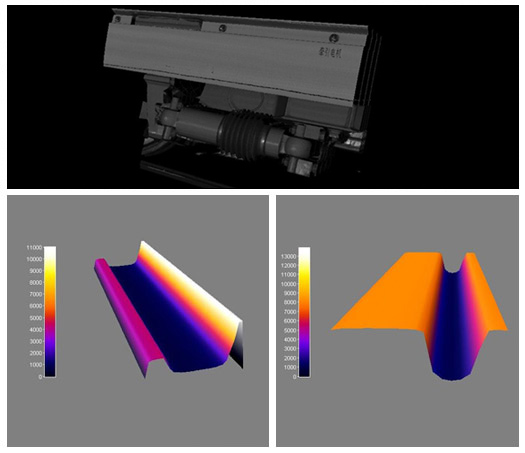
Products and features to help with High Dynamic Range
Below we show and describe useful features for applications where High Dynamic Range is needed, but typically are plagued by processing time and image degradation. We explain how Gidel can provide HDR in real time, compress and correct the image for a great image.
For High Dynamic Range (HDR) context, download our HDR whitepaper for an optional review. And/or let these images motivate the topic:
Courtesy Gidel
The aerial imaging application is just an example – the principle is widely applicable. They key context for HDR is that many imaging scenes are high-contrast, with deeply nuanced darker regions and equally nuanced brighter regions.
If one controlled for a single-exposure duration across all regions, whether by fixed timing or average pixel saturation, the one-exposure-fits-all image is likely to be a poor or unusable compromise – like the “original image” shown above left. One exposure can’t allow you to see the darks and brights. Either your exposure set to see the dark will saturate the brights… or if you optimize exposure to see the nuanced brights it will make the darks so dark you can’t distinguish them.
At the risk of sounding like an advertisement for laundry detergent about whiter whites and preserving colors, one doesn’t have to dwell on how HDR is achieved to recognize the HDR image shown above right is an improvement over the non-HDR original.
There are other helpful tools besides just HDR
HDR is an often powerful technique to effectively expand the dynamic range of the delivered image. But HDR isn’t always needed, and isn’t always the best tool, whether alone or in combination. Consider also tools and techniques like compression, gamma correction, and white balance – a bit more on each of these below – advantages Gidel can offer.
Compression
Another sometimes-useful technique is compression, reducing transmission volume (and time). Ideally one seeks lossless or low-loss compression, but that’s a tradeoff typically determined by assessing performance outcomes against any rigor or risk requirements for outlying cases. Often “good enough” and demonstrably reliable is the preferred choice.
If your application is NOT challenged by data transfer volume and time… whilst sending uncompressed images, then you don’t need compression. Conversely, might compression speed up your application for a competitive advantage?
Or thinking outside the box, might there be innovative applications doable with compression that aren’t possible without it? Let us help you do the math. Or try some applied testing.
Yet another digital imaging tool is gamma correction, an operation on luminance values. It was originally introduced to adapt digital images and map them better to human visual perception, due to the ways our eyes perceive brightness. BUT it also helps machine vision algorithms perform better by linearizing color and brightness data. That can improve accuracy in object tracking and color segmentation, for example.
Likewise for white balance. Here too the origin of white balance was to create a more pleasing image for human viewers of digitally rendered images, so that “white” objects appear white even if the light source skewed a bit blue or yellow, for example.
It turns out that white balance is also important for machine vision. By white balancing to the light source (if sunlight, it changes throughout the day), whether natural or artificial, color segmentation and mapping is improved. Whether doing inspection, object identification, or medical imaging, accurate color mapping is essential.
With HDR, Compression, white balance and Gamma correction
Throwing the whole kitchen sink at it, consider the following image pairs:
Right-hand image benefits from HDR, white-balance, gamma correction, and compression – Courtesy Gidel
Do it in real-time, on board the frame grabber from Gidel
The above illustrations are pretty compelling. But imagine if that had to happen on your host PC, operating on large raw data images, while trying to keep up with incoming data from the camera that might overwhelm the PC’s ability to achieve the desired machine vision decisions. That’s where Gidel’s FPGA frame grabbers excel. They receive the raw image stream from the camera, and do real-time value-added pre-processing – very fast – before passing the improved (and optionally compressed) image to the host software. So the workload on the host is reduced.
Better images – faster
With many engineering design challenges, it can be difficult or impossible to simultaneously satisfy “qualitatively better” as well as “faster performance” criteria. Indeed some conceptualizable applications may not be doable in practice due to such constraints. Or may not be affordable with common interfaces.
With Gidel’s FPGA frame grabbers, you get improved speed and high-quality actionable images – for high-performance applications that deliver.
About you: We want to hear from you! We’ve built our brand on our know-how and like to educate the marketplace on imaging technology topics… What would you like to hear about?… Drop a line to info@1stvision.com with what topics you’d like to know more about.
Recently we announced Allied Vision’s 5GigE SWIR Goldeye Pro cameras. Pretty cool. Pun intended. Click that link above for the 10,000 foot view of the camera series, features, and value proposition overall.
SWIR cameras come in both cooled and uncooled models
So you are already doing Short-Wave-InfraRed imaging, or think you might want to. For all the reasons and applications discuss in our SWIR cameras and applications knowledge-base article.
Cooled vs uncooled performance – what are the differences?
As with many engineering design choices and product selection options, for a given application one needs components that are good enough – perhaps with a little margin – to get the job done. But not overdesigned – as that would add cost, weight, and volume delivering no measurable benefit.
5GigE SWIR Goldeye Pro – Courtesy Allied Vision – a TKH Company
Thermoelectric cooling (TEC)
The InGaAs (indium gallium arsenide) sensors used for SWIR imaging deliver the best images when temperature-stabilized. That’s provided by the thermoelectric cooling (TEC). That helps reduce dark noise and thermal current.
With TEC, see key performance metrics
For the Goldeye Pro G5-320, we snapshot key metrics from the datasheet:
Goldeye Pro G5-320 imaging metrics – Courtesy Allied Vision – a TKH Company
Compare to uncooled Goldeye G-033 metrics:
Uncooled Goldeye G-033 imaging metrics – Courtesy Allied Vision – a TKH Company
Sensor performance comparison summary
For background on sensor performance testing, review our tutorial on EMVA 1288 attributes and standards. There we go into the meaning of key terms like dark noise, dark current, saturation capacity, and dynamic range.
While the G-033 and G5-320 sensors above are different in size and release date, they are both InGaAs sensors, so share essential basic characteristics. And we can be sure that Allied Vision engineered each camera for the best possible performance relative to housing design, electronics positioning, and so forth.
Camera
G5-320
G-033
Temporal dark noise
183 e~
390 e~
Dark Current
8.9 ke~/s
430 ke~/s
Dark current and temporal dark noise mitigated by cooling an InGaAs sensor
What performance requirements does your SWIR application require?
We love to learn about client applications, and to guide you to best-fit selections for sensors, cameras, lenses, lighting, and software. Whether you are new to SWIR or experienced, let us help!
About you: We want to hear from you! We’ve built our brand on our know-how and like to educate the marketplace on imaging technology topics… What would you like to hear about?… Drop a line to info@1stvision.com with what topics you’d like to know more about.
Since 1994, Gidel has been a leading provider of high-performance FPGA-based imaging and vision solutions. Their product offerings are engineered for data-intensive applications that demand real-time processing and minimal latency.
Key product categories – Courtesy Gidel
For high-end vision and imaging applications, compression, and HDR
…. for light-weight applications with fewer demands you may not need Gidel’s products.
Below is an overview of Gidel’s high-performance products.
… for superior throughput and pre-processing to reduce data load, you absolutely might need Gidel
Example application: Traffic monitoring with 12x 10GigE cameras
Conventional approach: Multiple computers needed to handle the data volume, and the need to coordinate them in a managed solution
With Gidel’s FPGA-based GigE parsing: Single computer solution is possible
Another example: Aerial imaging with FPGA processing:
Conventional approach: Raw image data provided “as is” to host PC and software, then “good luck” from there
With Gidel HDR processing: FPGA in framegrabber does HDR enhancement before passing to host PC
Courtesy Gidel
FPGA Accelerators and development tools
Courtesy Gidel
Robust off-the-shelf and ready-to-use solutions
Accurate triggering despite velocity instability
Ideal when: precise timing must be maintained even when speed varies
Example application: Rail inspection – the rail car on which the inspection system is mounted moves at the variable speed of the train, but track inspection must be continuous at defined minimum intervals.
Real-time data reduction and optimization
Compression— Ideal for recording, streaming, and cloud-based AI workflows
Feature extraction — Common in machine vision to minimize readout and host processing by focusing only on relevant image regions
HDR processing — Converts 10–16-bit input to 8-bit output in real time
Parallel operation —Simultaneous binning and full ROI processing for efficient mixed-resolution acquisition
Note: Early or crude attempts at compression reduced data volumes but at the cost of quality, struggling for images that were “good enough”. High-quality compression and feature extraction achieve both goals.
Left: Generated by conventional processing; Right: Generated using Gidel’s FPGA processing library – Courtesy Gidel
First a one paragraph tutorial on edge computing: By putting computing power closer to the source (in this case one or more digital cameras), helpful processing adds value and either “makes the decision at the edge” and/or reduces data volumes that need transmitting to the central host PC.
For high-bandwidth applications. Integrate high-end image acquisition with real-time image processing and/or compression.
Powered by a Nvidia Jetson™ embedded computer with optional pre-processing and compression capabilities.
With Gidel’s InfiniVision™ open frame grabber flow, over 100 sensors can be simultaneously synchronized and processed.
… for those who want flexibility to extend and tailor beyond the off-the-shelf solutions
e.g. Replace the need to build your own frame grabber — Gidel allows you to implement and control your acquisition interface directly in the FPGA.
Other applications: Food processing
Low-latency inline execution – since decisions must happen within milliseconds
Also:
Courtesy Gidel
Most-recent award
Gidel’s Quality+ Compression technology has been named one of the Top 10 Innovations of 2025 by inVISION Magazine. Achieve 1:10 compression ratios while preserving the original image quality, ensuring critical details remain intact for applications where lossless accuracy is essential. Latency under a single frame, processing over one GB Pixels/sec.
Courtesy Gidel
Complex products… happy to guide you
Due to their high-performance, it’s not so easy to illustrate everything these Gidel products can do with a simple overview. One needs to dig into spec sheets and look at details – if you want a bottom up approach. Alternatively, tell us about your application, and we do a top-down analysis to guide you to a solution with optimal cameras, grabbers, computers, and tools. Whether by phone at 978-474-0044, or by web-form below, we’re happy to advise.
About you: We want to hear from you! We’ve built our brand on our know-how and like to educate the marketplace on imaging technology topics… What would you like to hear about?… Drop a line to info@1stvision.com with what topics you’d like to know more about.
For 3D in-line measurement and inspection applications across various industries such as battery, automotive, lumber inspection, factory automation, logistics, and more. Constant profile rate of 5,000 profiles per second, along with real-time processing. Cost-effective, eye-safe red or blue lasers. Up to 1,700 mm field-of-view. Up to 675 mm Z-range.
Z-Trak Express laser line profiler series – Courtesy Teledyne DALSA
Newest series in large Z-Trak product line
Teledyne DALSA now offers four distinct 3D laser profiler series in its Z-Trak product line. Each member of the four series is a compact high-performance 3D laser profiler sensor. Each delivers high resolution height measurements using laser triangulation techniques. Each 3D profiler is factory calibrated to ensure accurate, consistent results.
IP67 protection for harsh environments
And each is built with IP67 protection to withstand the demands of harsh industrial environments making them suitable for industrial applications such as factory automation, metrology, surface, semiconductor, and parts inspection.
Z-Trak Express in particular
Key features – Courtesy Teledyne DALSA
Additional features and capabilities – Courtesy Teledyne DALSA
Detailed specs for each member of the series
You can find all the specs in the datasheets. For all Z-Trak laser profilers, see the Z-Trak product family overview. Then drill in on any specific family for more information.
Click the table for enlarged view – Courtesy Teledyne DALSA
Sometimes a single Z-Trak profiler is enough
But for some applications one might want to combine two or more sensors, in various spatial configurations:
Combine multiple units according to application requirements – Courtesy Teledyne DALSA
To simplify deployment and reduce costs, the Z-Trak Express 1K5 synchronizes multiple sensors via the data cables and supports content-based triggering for enhanced flexibility.
Which Z-Trak 3D camera is best for my application?
See our blog on key characteristics of 3D laser profiling, as a basis for choosing among Z-Trak 3D cameras. Or let us guide you through it by phone: 978-474-0044. Or use the form below. Together we can do this!
About you: We want to hear from you! We’ve built our brand on our know-how and like to educate the marketplace on imaging technology topics… What would you like to hear about?… Drop a line to info@1stvision.com with what topics you’d like to know more about.
Available in 5.3 and 3.2 MP sensor options, the 5 GigE interface delivers framerates exceeding 100 fps. Based on the TEC-version of Sony’s IMX992/993 SenSWIR sensors, the cameras are sensitive from 400nm to 1,700nm, so they are classified as VSWIR. With a single sensor covering both the visible and SWIR range, new economies are possible for applications needing that spectral coverage.
Even if you don’t need VIS and just want SWIR…
These are compelling for SWIR applications for two key reasons:
They achieve impressive framerates for large sensors (by SWIR standards), at 115 fps for the 5.3 MP, and 159 fps for the 3.2 MP model. With a very affordable 5 GigE interface.
Outstanding image quality ideal for demanding applications.
Goldeye Pro – Courtesy Allied Vision – a TKH Vision brand
Our previous “coming soon” blog summarized key features, suggested applications, and a first look, so below we’ll go deeper now that the products are fully released.
Thermoelectric cooling (TEC) for image quality
The InGaAs (indium gallium arsenide) sensors used for SWIR imaging deliver the best images when temperature-stabilized. That’s provided by the thermoelectric cooling (TEC). That helps reduce dark noise and thermal current.
Must an InGaAs SWIR camera use TEC?
No, it’s not a requirement. Allied Vision is a leading producer of SWIR cameras, and while many include thermoelectric cooling, certain models do not. See all Allied Vision SWIR cameras and note some are “TECless.”
Whether your application requires TEC or not comes down to framerates, duty cycles, and overall performance demands. As with many engineering and design questions, how good is good enough?
Overview
Here are the key specifications at a glance:
Goldeye Pro models at a glance – Courtesy Allied Vision – a TKH Vision brand
Both provide digital binning and gain control to increase sensitivity.
And there are multiple user sets are available to simplify camera setup.
Applications
SWIR sees things that visible imaging cannot. (Likewise for UV, but that’s beyond the scope of this piece.) SWIR imaging can be mapped to “pseudo” images for human viewing – if required.
More to the point, machine vision applications get the job done in real-time without human involvement. Sort those materials. Monitor the perimeter for intruders. Optimize crop irrigation. etc.
If SWIR pseudo images help to get the juices flowing, here are a few:
Visible vs. SWIR image pairs – Courtesy Allied Vision – a TKH Vision brand
Vision Systems Design award-winner
While the award was earned in China, the cameras perform the same in whatever country they are deployed in.
About you: We want to hear from you! We’ve built our brand on our know-how and like to educate the marketplace on imaging technology topics… What would you like to hear about?… Drop a line to info@1stvision.com with what topics you’d like to know more about.
Except for sometimes compelling line-scan imaging, machine vision has been dominated by frame-based approaches. (Compare Area-scan vs. Line-scan). With an area-scan camera, the entire two-dimensional sensor array of x pixels by y pixels is read out and transmitted over the digital interface to the PC host. Whether USB3, GigE, CoaXPress, CameraLink, or any other interface, that’s a lot of image data to transport.
Event-based sensing as alternative to frame-based approach
If your application is about motion, why transmit the static pixels?
The question above is intentionally provocative, of course. One might ask, “do I have a choice?” With conventional sensors, one really doesn’t, as their pixels just convert light to electrons according to the physics of CMOS, and readout circuits move the array of charges on down the interface to the host PC, for algorithmic interpretation. There’s nothing wrong with that! Thousands of effective machine vision applications use precisely that frame-based paradigm. Or the line-scan approach, arguably a close cousin of the area-scan model.
Consider the four-frame sequence to the left, relative to a candidate golf-swing analysis application. Per the legend, with post-processing markup the blue-tinged golfer, club, and ball are undersampled in the sense that there are unshown phases of the swing.
Meanwhile the non-moving tree, grass, and sky are needlessly re-sampled in each frame.
It takes an expensive high-frame-rate sensor and interface to significantly increase the sample rate. Plus storage capacity for each frame. And/or processing capacity – for automated applications – to separate the motion segments from the static segments.
With event-based sensing, introduced below, one can achieve the equivalent of 10k fps – by just transmitting the pixels whose values change.
Images courtesy Prophesee Metavision.
Event-based sensing only transmits the pixels that changed
Unlike photography for social media or commercial advertising, where real-looking images are usually the goal, for machine vision it’s all about effective (automated) applications. In motion-oriented applications, we’re just trying to automatically control the robot arm, drive the car, monitor the secure perimeter, track the intruder(s), monitor the vibration, …
We’re NOT worried about color rendering, pretty images, or the static portions in the field of view (FOV). With event-based sensing, “high temporal imaging” is possible, since one need only pay attention to the pixels whose values change.
Consider the short video below. The left side shows a succession of frame-based images for a machine driven by an electric motor and belt. But the left hand image sequence is not a helpful basis for monitoring vibration with an eye to scheduling (or skipping) maintenance, or anticipating breakdowns.
The right-hand sequence was obtained with an event-based vision sensor (EVS), and absolutely reveals components with both “medium” and “significant” vibration. Here those thresholds have triggered color-mapped pseudo-images, to aid comprehension. But an automated application could map the coordinates to take action, such as gracefully shutting down the machine, scheduling maintenance according to calculated risk, etc.
Courtesy Prophesee Metavision
Another example to help make it real:
Here’s another short video, which brings to mind applications like autonomous vehicles and security. It’s not meant to be pretty – it’s meant to show the sensor detects and transmits just the pixels that correlate to change:
Courtesy Prophesee Metavision
Event-based sensing – it really is a different paradigm
Even (especially?) if you are seasoned at line-scan or area-scan imaging, it’s a paradigm shift to understand event-based sensing. Inspired by human vision, and built on the foundation of neuromorphic engineering, it’s a new technology – and it opens up new kinds of applications. Or alternative ways to address existing ones.
Event-based sensing as alternative to frame-based approach
Download the whitepaper and learn more about it! Or fill out our form below – we’ll follow up. Or just call us at 978-474-0044.
About you: We want to hear from you! We’ve built our brand on our know-how and like to educate the marketplace on imaging technology topics… What would you like to hear about?… Drop a line to info@1stvision.com with what topics you’d like to know more about.
Industrial machine vision camerainterfaces continue to develop, allowing cameras to transfer megapixel images at extremely high frame rates. These advancements open up endless applications, however each machine vision camera interface has its own pros and cons.
Selecting the best digital camera interface can be done by taking in several considerations, helping you to make an optimal selection.
The following are some considerations in making an interface selection.
Bandwidth (Resolution and frame rate)
Cable Length
Cost
Complexity
Updated whitepaper available
For a comprehensive treatment of these issues, links to various standards and products, and a helpful comparative table, download our freshly updated whitepaper Camera Interfaces Explained:
Download whitepaper Camera Interfaces Explained
Some of what’s in that whitepaper – just a teaser view
Bandwidth: This is one of the biggest factors in selecting an interface as it essentially is the size of the pipe to allow data to flow. Bandwidth can be calculated by (resolution) x (frame rate) x (bit depth). You essentially find out pixels / second x the frame bit depth resulting in your total Megabits / second (Mb/sec). Large frame sizes at high speeds will require a large data pipe! If not, you’ll be bandwidth limited, so one would need to reduce the frame rate and image size or a combination of both.
Cable Length: The application will dictate the distance between the camera and industrial computer. In factory automation applications, the cameras can be located in most cases within meters from the computer vs a stadium sports analytics application requiring 100’s of meters.
Assorted machine vision cables – Courtesy CEI
Cost: Budgets must also be considered. Interfaces such as USB are very low cost versus a CoaxPress interface which will require a $2K frame grabber and more expensive cables.
Complexity: Not all interfaces are plug and play and require more complex configuration. If you are leaning towards interfaces using frame grabbers and have no vision experience, you may want to elect using a certified systems integrator.
Digital machine vision camera interfaces
The interfaces each have pros and cons aside from the designated bandwidth, cable lengths and costs, and are outlined as follows:
USB2.0 is an older standard for machine vision cameras and now superseded by USB3.0 / 3.1 . Early on, this was popular allowing cameras to easily plug and play with standard USB ports. This is still a great option for lower frame rate applications and comes with low cost. Click here for USB2 cameras.
USB3.0 / 3.1 is the next revision of USB2.0 allowing high data rates, plug and play capabilities and is ratified by the AIA standards, being “USB3 Vision” compliant. This allows plug and play with 3rd party software following the GENICAM standards. Cables lengths are limited to 5 meters, but can be overcome with active and optical cables. Click here for USB3 cameras
GigE Vision was introduced in 2006 and is a widely accepted standard following GENICAM standards. This is a the most popular high bandwidth interface allowing plug and play capabilities and allowing long cable lengths. Power Over Ethernet (PoE) will allow 1 cable to be used for data and power making a simpler installation. GigE is still not was fast as USB3.0, but has benefits of 100 meter cable lengths. Click here for GigE cameras.
5 GiGe (aka N-base T) & 10GigE similar to USB2 moving to USB3, is the next iteration of the GigEVision standard providing more bandwidth. Both follow the same GigE Vision standards, but now at higher bandwidths. Specific NIC cards will be required to handle the interface. Click here for 5 GigE cameras.
The following interfaces typically require frame grabbers:
CoaxPress (CXP) is a relatively new standard released in 2010, supported by GENICAM, utilizing coax cable to transmit data, trigger signals and power using one cable.. It is a scaleable interface via additional coax cables supporting up to 25Gb/s (3125MB/s) and higher now with CXP12. The interface can support extremely high bandwidth as seen in the above chart with long cable lengths to 100+ meters depending on the configuration. This interface requires a frame grabber which adds cost and some complexity in the overall setup. Click here for CoaxPress cameras
Camera link is a well established standard, dedicated machine vision standard released in 2000 allowing high speed communications between cameras and frame grabbers. It includes provisions for data, communications, camera timing and real time signaling to the camera. A frame grabber is required similar to CXP adding cost and some complexity and is limited in cable lengths to 10 meters. Longer cable lengths can be achieved with active and fiber optic cable solutions which additionally add cost. Click here for CameraLink cameras
CameraLink HS is a dedicated machine vision standard taking key aspects of CameraLink and expanding upon it with more features. This is a scaleable high speed interface with reliable data transfer and long cable lengths up to 300+ meters with low cost fiber connections. Similar to CXP and camera link a frame grabber is required adding cost. Click here for Cameralink HS cameras
Only in the full whitepaper:
Single-table one-page comparison of key interface attributes, including data throughput, cable lengths, powering options.
DOWNLOAD WHITEPAPER TO VIEW COMPREHENSIVE TABLE
Helpful tips and practical advice
Emerging standards updates
For a comprehensive treatment of these issues download our freshly updated whitepaper Camera Interfaces Explained:
Download whitepaper Camera Interfaces Explained
If you prefer to be guided, just call us at 978-474-0044. Tell our sales engineer a bit about your application, and we’ll help guide you to a best-fit solution.
About you: We want to hear from you! We’ve built our brand on our know-how and like to educate the marketplace on imaging technology topics… What would you like to hear about?… Drop a line to info@1stvision.com with what topics you’d like to know more about.
OEM vision system builders often favor bare board cameras. They are typically very small and compact, attractively priced, and easy to fit into small spaces. Ideal for embedding into systems of your own design.
Alvium housed camera (red) vs. Alvium Frame in metallic aluminum – Courtesy Allied Vision
But sensor alignment can be challenging – enter the Alvium Frame
With a traditional housed camera, the sensor is typically aligned within the camera, to very precise tolerances. That insures that when the lens is mounted, the field of view is optimally transferred through the optics and onto the sensor, without introducing tip/tilt/focus losses.
Conversely, a board level camera is wonderfully compact, “just” a sensor and other electronics on a printed circuit board (PCB). But the integrator, often an OEM systems developer, is then left to his own skills aligning the PCB optical sensor and a corresponding lens. Even the most skilled mechanical engineers and systems builders can find optical alignment challenging. The tolerances are very fine, and besides optics knowledge and experience, it often takes special instrumentation and tooling to set, test, and tune the alignment. And then to insure the positioning remains stable relative to future vibrations once deployed in the target system.
Alvium Frame – sized like a board, aligned like a camera
Allied Vision’s innovation with the Alvium Frame was to recognize a market for something almost as small as a board level camera, yet sensor-aligned in a frame. And with helpful heat dissipation characteristics besides.
Give us some brief idea of your application and we will contact you to discuss camera options.
What happens if the sensor isn’t well-aligned?
Image quality can be negatively affected, by getting the geometry wrong. Optics is all about mapping the real world target through a lens and onto the 2D array of pixels in the sensor. So true orientation without rotation in the X or Y axis is preferred, as is proper depth in the Z axis, and avoidance of tip or tilt.
Consider the following illustration of sensor rotation off by just 1 degree. While the camera body and PCB board being imaged were squared to each other, for this illustration the sensor was rotated by 1 degree around the Z axis. It would not pass the alignment process in manufacturing production and quality control like this! Notice how the white line slopes down to the right, for this misaligned sensor.
Whether your application is PCB inspection, optometry, lasers, or any precision work, optical alignment matters.
Misaligned sensor causes horizontal white line to appear sloped – Courtesy Allied Vision
Sensor tip/tilt impacts Modulation Transfer Function (MTF)
In our blogs, newsletters, Tech Briefs, and Knowledge Base, we periodically talk about the Modulation Transfer Function (MTF). It’s an important measure of lens performance. One typically seeks a lens that’s more than good enough for the task at hand, just as one’s camera, sensor, lighting, and data rates each have to be up to the job – a system is no better than its weakest link.
But a lens’ reported MTF is based on testing instances of the lens mounted on cameras with precisely aligned sensors. Any tip or tilt of the sensor away from the orthogonal plane might not greatly impact the central area of the image. But even a little tip or tilt, with the top leaning forward and the bottom backward, or the other way around, may lead to out-of-focus conditions away from the center of the sensor.
So even if the lens’ MTF is very good, an insufficiently aligned sensor can drag down imaging performance. Which is why it’s important to know the engineering tolerances of every optical component – or to trust your provider publishes and warranties their tolerances.
Alvium camera family – more than 200 variants
First came the “original” Alvium housed camera, of which there are more than 10 members in each of 1GigE and 5GigE interfaces. These compact cameras are attractively priced, with a range of sensors, and are feature-rich.
Alvium G1 with lens – Courtesy Allied Vision
Variations are available through the Alvium Flex concept, with options for Open Housing, Flex Frame, and Bare Board. Designed for space-constrained applications, the Alvium Flex cameras offer USB and MIPI CSI-2 interfaces. Still feature-rich and with many sensor options, pricing in single or small quantities, or OEM volumes are available.
Alvium Flex options – Courtesy Allied Vision
In another nod to OEM customers, the USB3 version of the Alvium Flex Frame has a choice of 2 interface positions, a rear exit (1800) or a side exit (90), as shown below:
Interface options helpful for tight spaces – Courtesy Allied Vision
So the Flex Frame offering fills a niche between housed vs. board level cameras. It’s close in size to board level, but with the alignment benefits of a housed camera.
So what are the alignment tolerances?
Let’s use the diagram and definition of terms below as a framework:
Sensor shift and rotation framework – Courtesy Allied Vision
For housed-sensor Alvium models, Allied Vision asserts the following manufacturing accuracy for sensor positioning:
Did I read that right? Frame model tolerances tighter than housed?
Exactly. Sensor shift in the x/y axis is +/- 90 µm in for Alvium Frame models fully 60 µm tighter tolerance than the +/- 150 µm for sensors in the housed Alvium models.
Likwise in the z axis, the optical back focal length is within 0 to -50 µm for the Alvium Frame models, while the Alvium housed models are factory calibrated to within 0 to -100 µm.
Other features of the Alvium Frame
In addition to the optically important sensor alignment, the frame helps to dissipate heat via the metallic surface area, a benefit over a bare-board approach. The frame has 4 M2 screw holes for easy mounting. And there are two options to help you align the Alvium Frame within your own system:
Two options to align Alvium Frame units – Courtesy Allied Vision
About you: We want to hear from you! We’ve built our brand on our know-how and like to educate the marketplace on imaging technology topics… What would you like to hear about?… Drop a line to info@1stvision.com with what topics you’d like to know more about.
Remember when machine vision pioneers got stuff done with VGA sensors at 0.3MP? And the industry got really excited with 1MP sensors? Moore’s law keeps driving capacities and performance up, and relative costs down. With the Teledyne e2v Emerald 67MP sensor, cameras like the Genie Nano-10GigE-8200 open up new possibilities.
12MP sensor image – Courtesy Teledyne DALSA
67MP sensor image – Courtesy Teledyne DALSA
So what? 67MP view above right doesn’t appear massively compelling…
Well at this view, without zooming in, we’d agree….
But at 400% zoom, below, look at the pixelation differences:
Both images below show the same target region, with the same lighting and lens, and each zoomed (with Gimp) to 400%. There is so much pixelation in the 12MP image to raise doubts about effective edge detection on either the identifying digits (33) or for the metal-rimmed holes. Whereas the 67MP image has far less pixelation, thereby passing a readily usable image to the host for processing. How much resolution does your application require?
12MP zoomed 400%
67MP zoomed 400%
Important “aside”: Sensor format and lens quality also important
Sensor format refers to the physical size of the sensor and the pixel shape and pixel density. Of course the lens must physically mount to the camera body (e.g. S, C, M42, etc.), but it must also create an image circle that appropriately covers the sensor’s pixel array. The Genie Nano-10Gige-8200 uses the Teledyne e2V Emerald 67M packs just over 67 million pixels, each square pixel just 2.5 µm wide and high, onto a CMOS sensor measuring only 59mm x 59mm.
Consider other good quality cameras and sensors, with pixel sizes in the 4 – 5 µm range, which leads to EITHER fewer pixels overall in the same size sensor array; OR to a much larger sensor to accommodate more pixels. The former may limit what can be accomplished with a single camera. The latter would necessarily make the camera body larger, the lens mount larger, and the lens more expensive to manufacture.
The lens quality, typically expressed via the Modulation Transfer Function (MTF), is also important. Not all lenses are created equal! A “good” quality lens may be enough for certain applications. For more demanding applications, one would be wasting a large format sensor if the lens’ performance fails below the sensor’s capabilities.
Two different lenses were used to take the above images, both fitting the sensor size. However the right image was taken with a lens designed for smaller pixels versus the left. – Courtesy Teledyne DALSA
The high-level views of the test chart above tease at the point we’re making, but it really pops if we zoom in. Look at the difference in contrast in the two images below!
Lens nominally a fit for the sensor format and mount type, but NOT designed for 2.5 µm pixels.
Lens designed for 2.5 µm pixels.
The takeaway point of this segment is lensing matters! The machine vision field benefits users tremendously with segmented sensor, camera, lensing, and lighting suppliers. Even within the same supplier’s lineup, there are often sensors or lenses pitched at differing performance requirements. Consider our Knowledge Base guide on Lens Quality Considerations. Or call us at 978-474-0044.
Another example:
Below see the same concentric rings of a test chart, under the same lighting. The left imaged was obtained with a good 12MP sensor and good quality lens matched to the sensor format and pixel size. The right imaged used the 67MP sensor in the Genie-Nano-10GigE-8200, also with a well-matched lens.
12MP sensor, zoomed 1600%
67MP sensor, zoomed to same FOV
If you need a single-camera solution for a large target, with high levels of detail, there’s no way around it – one needs enough pixels. Together with a well-suited lens.
Genie Nano 10GigE 8200 – Courtesy Teledyne DALSA
The Genie Nano 10GigE 8200, in both monochrome and color versions, is more affordable than you might think.
Once more with feeling…
Which of the following images will lead to the more effective outcomes? Choose your sensor, camera, lens, and lighting accordingly. Call us at 978-474-0044. Our sales engineers love to create solutions for our customers.
About you: We want to hear from you! We’ve built our brand on our know-how and like to educate the marketplace on imaging technology topics… What would you like to hear about?… Drop a line to info@1stvision.com with what topics you’d like to know more about.
We don’t use terms like paradigm-shift lightly. Event-based vision (EBV) is shaking things up just as much as the arrival of frame-based and line-scan imaging once did . It’s that different. And why we are excited to offer Prophesee sensors and cameras.
Event-based vision applications areas – Courtesy Prophesee
Applications examples… and just enough about concepts
This informational blog skews towards applications examples, with just enough about concepts and EBV technology to lend balance. Event-based vision is so new and so different than previous vision technologies. We believe our readers may appreciate an examples-driven approach to understanding this radically new branch of machine vision.
Unless you’re an old hand at event-based vision (EBV) …
…and as of this writing in Summer 2025 few could be, let’s show a couple of short teaser videos before we explain the concepts or go deeper on applications.
Example 1: High-speed multiple-object counting and sizing
The following shows a use of event-based imaging to both count particles or objects and to estimate their size. All in a high-speed multiple concurrent target environment.
Courtesy Prophesee
Example 2: Eye-tracking – only need to track pupil changes
Now consider eye-tracking: in the video below, we see synchronized side-by-side views of the same scene. The left side was obtained with a frame-based sensor. The right side used a Prophesee event-based sensor. Why “waste” bandwidth and processing resources separating a pupil from an iris, eyelids, and eyebrows, when the goal is eye-tracking?
Courtesy Prophesee
Radically increased speed; massively less data
Prophesee Metavision‘s sensor tracks “just” what changes in the field of view, instead of the frame-based approach of reading out whole sensor arrays, transmitting voluminous data from the camera to the host, and algorithmically looking for edges, blobs, or features.
Example 3: Object tracking
Not unlike the eye-tracking example above, but this time with multiple moving targets – vehicular traffic. With frame-based vision, bandwidth and processing has to repeatedly process static pavement, light poles, guard rails, and other “clutter” comprising 80% of the field of view. But with event-based vision the sensor only detects and transmits the moving vehicles.
Whether counting traffic for congestion planning/reporting, or collision avoidance abord a given vehicle, we don’t care what the vehicle looks like – only that it’s there and moving along a certain trajectory and at a detected speed.
Example 4: Surveillance and security
Prophesee named this video “Optical Flow Crowd”, which is best understood in the context of security and surveillance, we suggest. It’s not unlike the vehicular flow example above, except that cars and trucks mostly stay in-lane. Whereas pedestrians move at diverse angles. And their arm, leg, head, and torso movements also convey information.
The (computed) vector overlays indicate speed and directional changes, important to reveal potentially dangerous actions taken or likely to emerge. For example, does a raised arm indicate a handgun or knife being readied, or is it just a prelude to scratching an itchy nose? Is there a pursuer turning towards another pedestrian, to which a nearby policeman should be alerted?
Example 5: Vibration monitoring and preventative maintenance
Motorized equipment is typically service either on a preventative maintenance schedule and/or a break-fix approach, depending on costs, legal liabilities and risks, etc. What if one could inexpensively identify vibration patterns that reveal wearing belts or bearings before a breakdown and before there is preventable collateral damage to other components?
Courtesy Prophesee
Enough with the examples – how can I get event-based sensors?
1stVision is pleased to represent Prophesee with a wide range of sensors, evaluation kits, board-level and housed cameras, and an SDK designed for event-based vision applications.
Built on neuromorphic engineering principles inspired by the brain’s neural networks and human vision, Prophesee products are surprisingly affordable, enabling new fields of event-based vision. Or improving on frame-based vision applications that may be done better, faster, or less-expensively using an event-based approach.
About you: We want to hear from you! We’ve built our brand on our know-how and like to educate the marketplace on imaging technology topics… What would you like to hear about?… Drop a line to info@1stvision.com with what topics you’d like to know more about.
Machine vision systems are widely accepted for their value-add in so many fields. Whether in manufacturing, pick-and-place, quality control, medicine, or other areas, vision systems either save money and/or create competitive advantage.
From “black box” uncertainties to confident outcomes using T2IR – Courtesy Teledyne DALSA
BUT deploying new systems can be tricky
For experienced machine vision system builders, sometimes the next new system is either “simple” in complexity, or a minor variant on previously built complex systems in which one has good confidence. Deployment, systems acceptance testing and validation may be straightforward, with little doubt about correctness or reliability. Congratulations if that’s the case.
For new undertakings, even for experienced vision system builders, there’s often some uncertainty in the “black box” nature of a new system. Can I trust the results as accurate? Am I double counting? Am I missing any frames? If the system overloads, how can I track which inspections were skipped while the system recovers? How to troubleshoot and debug? And rising QA standards are pushing us to verify performance – yikes!
T2IR: Trigger to Image Reliability can open up the black box
Take the mystery out of system deployment, tuning, and commissioning. T2IR’s powerful capabilities essentially open up the black box. And for users of many Teledyne DALSA cameras and framegrabber products, T2IR is free!
Two minute overview of T2IR: Trigger to Image Reliability – Courtesy Teledyne DALSA
Bundled with many Teledyne DALSA products
The T2IR features are available at no cost for customers who purchase (or already own) any of:
Software: Sapera LT SDK (for both Windows and Linux)
T2IR in a nutshell
T2IR, Trigger to Image Reliability, is a set of hardware and software features that help improve system reliability. It’s offered as a free benefit to Teledyne DALSA customers for many of their cameras and framegrabbers. It helps you get inside your system to audit and debug image flow.
Example One: Coping with unexpected triggers
Consider the following diagram:
Courtesy Teledyne DALSA
To the left of the illustration we see the expected normal trigger frequency. Each trigger, perhaps from a mechanical event and an actuator sending an electronic pulse, triggers the next camera image, readout, and processing, at intervals known to be sufficient for complete processing. No lost or partial images. No overtriggering. All as expected.
But in the middle of the illustration we see invalid triggers interspersed with valid ones. What would happen in your system if you didn’t plan for this possibility? Lost or partial images? Risk of shipping bad product to customers due to missed inspections? Damage to your system? What’s the source of the extra triggers? How to debug the problem if found during design and commissioning? How to recover if system is already in production?
With T2IR, the Sapera API, may be programmed to detect the invalid triggers that are out of the expected timing intervals. An event can be generated for the application to manage. The application might be programmed to do something like “stop the system”, “tag the suspect images”, “note the timestamps”, or otherwise make a controlled recovery.
Key takeway: instead of the system just blundering along with the invalid triggers undetected, with possible grave consequences, T2IR can help create a more robust system that recovers gracefully.
Courtesy Teledyne DALSA
Example Two: Tracking and Tracing Images – Tagging with timestamps
Consider the challenges of high-speed materials handling, let’s say 3000 parts per minute. Some such systems require multiple cameras, lets say 4 per object, to make an accept, reject, or re-inspect decision on each component. For this hypothetical system, that would be 12,000 images per minute to coordinate!
Correlating up to thousands of images per minute – Courtesy Teledyne DALSA
The illustration above shows the timestamps one might assign with T2IR, based on ticks in microseconds, according to known or believed belt motion speed. But what if results seem corrupted using that method, or if there are doubts about whether speed is constant or variable?
With the Xtium frame grabber, one can use T2IR to choose among alternate timestamp bases beside the “hoped for” microsecond calculations:
So one might prefer to tag the images with and external trigger or a shaft encoder, which are physically coupled to the system’s movements, and hence more precise than calculated assumptions.
Consider the following screenshot, in the context of an Xtium framegrabber together with T2IR:
Diagnostic T2IR window for Xtium framegrabber – Courtesy Teledyne DALSA
The point of the above annotated screenshot is to give a sense of the level of detail provided even at this top level window – with drill ins to inspect an control diverse parameters, to generate reports, etc. This is “just” a teaser blog meant to whet the appetite – read the tutorial, speak with us, or see the manual, for a deeper dive.
T2IR Elements and Benefits – in more detail
Courtesy Teledyne DALSA
Conclusion
Every major machine vision camera and software provider offers an SDK and at least some configuration and control features. But Trigger to Image Reliability – T2IR – takes traceability and control to another level. And for users of so many Teledyne DALSA cameras, framegrabbers, and software, it’s bundled in at no cost!
About you: We want to hear from you! We’ve built our brand on our know-how and like to educate the marketplace on imaging technology topics… What would you like to hear about?… Drop a line to info@1stvision.com with what topics you’d like to know more about.
245 MP cameras in both monochrome and color models
SVS-Vistek, with 35 years experience developing machine vision cameras, releases their first SHR811 Super High Resolution cameras. Additional sensors and cameras will be released in the coming months. The first two SHR models, one each in monochrome and color, are based on the Sony IMX811 CMOS sensor.
Highlights at a glance (Left); LCD pixels (Right) – Courtesy SVS-Vistek
The right-hand image above may look like just a color grid – in fact it’s a segment of a 245 MP image from an LCD inspection application. So imagine a large HDTV or other flat panel showing a test pattern as part of post-production quality acceptance testing. The image is a segment of the inspection image showing just a subset grid of the activated pixels – at such resolution that machine vision algorithms can conclusively give each panel a clear pass or fail determination.
Frame rates to 12 fps might not sound impressive for certain applications, but for a 245 MP sensor, it’s pretty compelling. That’s achieved with the CoaXPress (CSP) interface.
For the SHR811 CCX12 COLOR cameraFor the SHR811 MCX12 MONOCHROME camera
Applications and Examples
The series name – SHR – already suggests the applications for which these cameras are intended – Super High Resolution. You may have innovative applications of your own, but classical uses include:
Electronics and PCB inspection
Display inspection
Semiconductor wafer inspection
Microscopy
High-end surveillance
Applications and examples – Courtesy SVS-Vistek
Additional applications include microscopy and surveillance:
SHR applications – Courtesy SVS-Vistek
Technical details
Based on the Sony IMX411, this remarkable sensor is the key technology around which SVS-Vistek has designed the SHR811 launch-model camera.
This sensor has 62% higher pixel density than the highly-successful Sony IMX411 sensor, at 2x the framerate, and similar sensor size. So it’s a classic example of Moore’s Law, with size reduction and performance improvements, as Sony builds on its track record of innovation.
1stVision overview of the SHR811MCX12 monochrome camera
Features
As one would expect, there is a comprehensive feature set, including:
SHR feature overview – Courtesy SVS-Vistek
To highlight one specific feature, consider the Sequencer capability. It allows a single trigger to begin a series of timed exposures, as described in the following short video:
Setting the Sequencer – Courtesy SVS-Vistek
For full specifications, go to the SVS-Vistek SHR camera family, drill in to a specific model, and see or download PDF Datasheet, Manual, Technical Drawing, and/or Sensor Spec. Or just call us at 978-474-0044 and let us guide you.
About you: We want to hear from you! We’ve built our brand on our know-how and like to educate the marketplace on imaging technology topics… What would you like to hear about?… Drop a line to info@1stvision.com with what topics you’d like to know more about.
Machine vision practitioners, regardless of application or lens type, know that contrast is essential. Without sharp definition, features cannot be detected effectively.
When using a telecentric lens for precision optical 2-D measurements, ideally one should also use collimated lighting. Per the old adage about a chain being only as good as its weakest link, why invest in great lensing and then cut corners on lighting?
WITH collimated light expect high edge definition:
The cost of the light typically pays for itself relative to quality outcomes. Below see red-framed enlargements of the same region of a part being imaged by the same telecentric lens.
The left-hand image was taken with a conventional backlight – note how the light wraps around the edge, creating “confusion” and imprecision due to refracted light coming from all angles.
The right-hand image was obtained with a collimated backlight – with excellent edge definition.
While telecentric imaging is a high-performance subset of the larger machine vision field in general, the same principles of resolution apply. It takes several pixels to confidently resolve any given feature – such as an edge – so any “gray areas” induced by lower quality lighting or optics would drag down system performance. See our blog and knowledge-base coverage of resolution for more details.
Collimated lighting in more detail
Above we see the results of using “diffuse” vs. “collimated” light sources, which are compelling. But what is a collimated light and how does it work so effectively?
UNLIKE a diffuse backlight, whose rays emanate towards the object at angles ranging from 0 to almost 180°, a collimated backlight sends rays with only very small deviations from perfectly parallel. Since parallel rays are also all that the telecentric lens receives and transmits on to the camera sensor, stray rays are mitigated and essentially eliminated.
The result is a high-contrast image which is easier to process with high-reliability. Furthermore, shutter speeds are typically faster, achieving necessary saturation more quickly, thereby shortening cycle times and increasing overall throughput.
Many lights to choose from:
The video below shows a range of light types and models, including clearly labeled direct, diffuse, and collimated lights.
Several light types – including clearly labeled collimated lights
[Optional] Telecentric concepts overview
Below please compare the diagrams that show how light rays travel from the target position on the left, through the respective lenses, and on to the sensor position on the far right.
A telecentric lens is designed to insure that the chief rays remain parallel to the optical axis. The key benefit is that (when properly focused and aligned) the system is invariant to the distance of the object from the lens. This effectively ignores light rays coming from other angles of incidence, and thereby supports precise optical measurement systems – a branch of metrology.
If you’d like to go deeper on telecentrics, see the following two resources:
About you: We want to hear from you! We’ve built our brand on our know-how and like to educate the marketplace on imaging technology topics… What would you like to hear about?… Drop a line to info@1stvision.com with what topics you’d like to know more about.
Nano hypercentric lenses designed for the inspection of small cavities and hollow parts with diameters from 0.75 to 10 mm. That’s the diameter of a drinking straw – and narrower!
HCN13010 and HCN13040 Nano Hypercentric lenses for small cavities – Courtesy Opto Engineering
Hypercentric lenses once more with feeling
Recently we introduced Opto Engineering’s HC hypercentric 360° lenses. They image cavity interiors from the outside by utilizing a specialized optical path that allows light to pass through bottlenecks and narrow openings. The variable iris provides maximum flexibility and a wide viewing angle to clearly image the fine details of the object. Their unique design facilitates complete internal surface inspection with no need to use a probe, rotate the object or use a complex multi-camera system.
HC 360° Series applications across whole lens family
Courtesy Opto Engineering
HCN Hypercentric nano lenses inspect tiny cavities from the outside
Consider cavities as small as 0.75 mm (0.029 in) ranging up to 10 mm (0.39 in), for items in the order of a drinking straw diameter (and smaller). These interiors can be inspected from the outside looking in, with the HCN Series lenses.
2 minute overview of lenses for hollow-part inspection – Courtesy Opto Engineering
About you: We want to hear from you! We’ve built our brand on our know-how and like to educate the marketplace on imaging technology topics… What would you like to hear about?… Drop a line to info@1stvision.com with what topics you’d like to know more about.
Goldeye Pro 5GigE SWIR camera – Courtesy Allied Vision – a TKH Vision brand
Coming soon – Goldeye Pro models with the TEC-version of Sony’s IMX992/993 SenSWIR sensors – tuned to 400nm – 1,700nm. We previously covered these sensors in Allied Vision’s compact uncooled Alvium cameras. Now Allied Vision brings these sensors to the Goldeye Pro lineup, with two important features: Thermoelectric cooling (TEC) and 5GigE interface.
1. Thermoelectric cooling (TEC)
Image quality is enhanced by thermoelectric cooling (TEC). Often paired with InGaAs sensors common in SWIR imaging cameras, Allied Vision now brings TEC to these CMOS Sony sensors. Why? Because cooling reduces thermal noise, creating a higher signal-to-noise ratio.
2. Fast 5GigE interface – framerates to 150fps
With the 5GigE interface, these SenSWIR cameras deliver frame rates above 100fps:
Courtesy Allied Vision – a TKH Vision brand
Visible vs. SWIR image pairs – Courtesy Allied Vision – a TKH Vision brand
But first, how about those SWIR images?
More about the new camera models in a moment, but first a reminder about SWIR. Short-wave infrared imaging enables machine vision applications beyond the visible portion of the spectrum.
Example applications
Per those striking image pairs at the top of the article, consider briefly:
Banknote validation: The SWIR application detects features unseen in the visible spectrum
Fluid fill levels: Able to see through even opaque plastic bottles, SWIR can monitor and control fill levels.
Materials detection: Whether for security or quality-control, many materials emit/reflect distinctly in the SWIR range, despite appearing identical under visible light.
Agriculture: Crop monitoring and irrigation applications are enabled by SWIR, which can detect moisture unseen by visible light. Fruit-sorting applications are also supported.
Back to the future
SWIR imaging isn’t new, but commercially it’s growing by leaps and bounds at present. Allied Vision has been an innovator and leader in SWIR for some time, and continues to expand their portfolio of SWIR cameras. While Allied Vision also offers SWIR capabilities in their compact Alvium models (with USB3, MIPI CSI-2, and GigE interfaces), their flagship SWIR offerings are found in the Goldeye product families.
The comprehensive Goldeye offering includes sensors that cover SWIR, XSWIR, and VSWIR portions of the spectrum. Some models are uncooled, while others provide cooling. You may know exactly what your application requires. Or you might appreciate our guidance.
More about Goldeye Pro 5GigE cameras
Noteworthy features include:
On-board automatic image correction
Stabilized sensor cooling without a fan
Lockable cable connectors
Power over Ethernet (PoE)
Spectral sensitivity
Sony SenSWIR wide spectral sensitivity – Courtesy Allied Vision – a TKH Vision brand
For full details…
This article was intended as a short overview of the new Goldeye Pro SWIR 5GigE cameras. See all Allied Vision Goldeye SWIR cameras, and Alvium SWIR cameras, including datasheets and comprehensive attributes. There are many choices now in SWIR, VSWIR, and XSWIR imaging. Tell us more about your application and we’ll be happy to advise.
About you: We want to hear from you! We’ve built our brand on our know-how and like to educate the marketplace on imaging technology topics… What would you like to hear about?… Drop a line to info@1stvision.com with what topics you’d like to know more about.
Recently we introduced the IDS Imaging event-based cameras, the uEye XCP-E models. These cameras are a paradigm shift – they detect changes in pixel brightness and transmit ONLY those changes. This dramatically reduces data load, lowers latency, and improves efficiency.
uEye XCP-E event based cameras – housed and board-level options – Courtesy IDS Imaging
Speed, speed, speed
Temporal resolution is better than 100μsec! Rapid changes can be detected – equivalent to an area scan camera operating at >10,000fps.
Paradigm shift – from “frames” to “events”
This is one of those aha moments. Too often we get jaded in believing that things only evolve incrementally – Moore’s law and electronics getting faster and less expensive, etc. Yawn. But this really is a game changer worth getting one’s head wrapped around.
Paradigm shift – an event-based sensor enables a new applications approach – Courtesy Sony / Prophesee
The event-based vision sensor (EVS) was developed by Sony and Prophesee.
Industrial use cases
With a radically new technology, even machine vision veterans may appreciate seeing example applications already utilizing event-based imaging:
Some typical applications for event-based imaging – Courtesy Sony / Prophesee
Example applications
The following are meant to be suggestive rather than inclusive. Just to whet the appetite.
Courtesy Sony / Prophesee
Let’s enlarge that “alternatives” comparison from the above graphic:
Which level of complexity, performance outcomes, and costs do you prefer? Courtesy Sony / Prophesee
Another class of applications
Courtesy Sony / Prophesee
Vibration monitoring can alert the need for preventative maintenance – Courtesy Sony / Prophesee
Take the guesswork out of when to do preventative maintenance. Maximize uptime. Reduce the risks of catastrophic failure. These cameras are affordable enough to let them do the vibration monitoring – just set your alert threshold!
Let the sensor monitor vibration frequencies – Courtesy Sony / Prophesee
Software for event-based imaging applications
New paradigm best served by Metavision Technology Software – Courtesy Sony / Prophesee
Metavision SDK modules built for event-based imaging applications – Courtesy Sony / Prophesee
Get it? Got it? Need it? Want it?
This is a new way of coming at machine vision applications. It may give you an edge over your competition by enabling you to improve quality, reduce costs, and/or innovate new products or services. It really is different. See the IDS Imaging uEye XCP-E event-based cameras and datasheets. Powered by the Sony IMX636 developed in conjunction with Prophesee.
Tell us more about your application, using the link below. Or just call us at 978-571-5552. We can help you determine whether event-based imaging is optimal for your application.
About you: We want to hear from you! We’ve built our brand on our know-how and like to educate the marketplace on imaging technology topics… What would you like to hear about?… Drop a line to info@1stvision.com with what topics you’d like to know more about.
JAI has over 60 years experience in the vision industry, and is likewise a longstanding part of the 1stVision portfolio. JAI produces a diverse range of cameras, including area scan and line scan; across multiple interfaces; and spanning visible, NIR, SWIR, and UV portions of the spectrum.
In this article we announce six new line scan camera models: 4 in the Sweep series at 4k each; and 2 in the Sweep+ series at 4k and 8k respectively. There’s a niche for every model.
Four new 4k line scan cameras – Courtesy JAI Imaging
Two new Sweep+ line scan cameras – one 4k one 8k – Courtesy JAI Imaging
Four new 4k line scan Sweep models; Two new Sweep+ models incl. 8k
At the risk of information overload, we’ve bundled this product release update of six new camera models across two product families into a single article. We hope the reader appreciates the compare-and-contrast approach as a way to understand the value proposition for each camera/family.
When you need line scan it’s nice to have options
While area scan sensors with big 2D pixel array outputs are right for some applications, line scan is a better fit for others. In particular, if the object being imaged is essentially continuous, line scan can be an effective way to take narrow image slices with a lower cost 1D sensor that’s long in just the dimension that maps to the object width. Movement of the object (or sensor) together with successive slices then creates the second dimension.
Example line scan applications – Courtesy JAI Imaging
JAI’s Sweep line scan cameras vs. Sweep+
JAI’s Sweep line scan cameras include a wide offering of monochrome, bilinear, and trilinear models, at 2K, 4K, 8K, and 16K. Interface options include 5GigE, 10GigE and CoaXPress. If you need color sensing, the bilinear approach is an affordable approach, and often plenty good enough. For true color capture, the trilinear sensors are superior – if needed.
Sweep+ cameras, as suggested by the + suffix, are JAI’s top of the line color and multispectral line scan products. The beam-splitter prism optics, together with three (color only models) or four (color plus NIR) sensors, deliver high-precision color resolution. Due to the data volumes generated, the Sweep+ cameras use CoaXPress, 10GigE, and CameraLink interfaces to achieve line rates suitable to the respective sensor sizes and anticipated applications.
Give us some brief idea of your application and we will contact you to discuss camera options.
Mini-tutorial on single sensor vs. multi-sensor color imagin
While Bayer filters or equivalent provide single sensor color, that’s good enough for some applications, there is some loss of color resolution via that inherent physical interpolation. So demanding applications take advantage of separate sensors for each segment of the spectrum, using a prism to separate wavelengths. The resulting camera is physically larger to accommodate the the prism, extra sensors, and electronics – but the best possible color performance is achieved.
A deeper dive on the new Sweep cameras
At-a-glance overview of the Sweep 4k cameras – Courtesy JAI Imaging
Monochrome line rates are 2x that of the bilinear color models
… because there is a single monochrome pixel mapped to the target object’s corresponding area.
Courtesy JAI Imagine
But if you need color the bilinear approach is an efficient way to do it, since there are only two rows of data transmitted for every real-space row imaged….
A peak at the bilinear approach to color line scan imaging
Courtesy JAI Imaging
Other JAI Sweep camera features
Keystone correction, aka tilted view correction, onboard the camera
More details on JAI’s new Sweep+ line scan cameras:
A 4k and and 8k model, both with CoaXPress interfaces – Courtesy JAI Imaging
The two new models round out the Sweep+ lineup – Courtesy JAI Imaging
Precise prism optical design yields superior images – Courtesy JAI Imaging
Some of the key benefits of CoaXPress – Courtesy JAI Imaging
And yet more features…
You get the idea… Sweep+ is a remarkable camera family. There are even more features to find in the Sweep+ product details and datasheets. Or just call us at 878-571-5683 for expert assistance. Tell us about your application requirements and we’ll guide you to an optimal camera. Lighting, lenses, filters, cables, and software too.
About you: We want to hear from you! We’ve built our brand on our know-how and like to educate the marketplace on imaging technology topics… What would you like to hear about?… Drop a line to info@1stvision.com with what topics you’d like to know more about.
The μEye XCP-E event-based camera utilizes Sony’s Prophesee IMX636 sensor. So, by design, it captures only relevant image changes. Event-based imaging can be a game changer for certain applications. Unlike area scan or line scan imaging – which capture every pixel and render a “full image” – event imaging only senses and delivers changes.
IDS μEye XCP-E housed camera (leftmost) and forthcoming XLS-E board level models – Courtesy IDS Imaging
Event-based imaging captures the changes:
Left: uEye XCP-E image vs. Right: Area scan image – Courtesy IDS Imaging
Less is more
Playing on the “less is more” adage reveals key insights into event-based imaging.
The human eye is adept at delivering and entire scene, of course, and that’s how most of us imagine we see the world around us. But our overall vision perception also builds upon the eye’s ability to sense brightness changes within small segments of the overall scene..
Consider a baseball batter awaiting a pitched ball. The overall scene is relatively static: the outfield fence, bases, and foul lines aren’t moving. And the infielders are almost static – relative to the motion of the ball. But the pitched ball approaching at 80 – 90 miles per hour can be identified by a good batter, to gauge “strike or ball” and “swing or take”.
The batter’s visual processing does NOT have time to capture the full scene at each instant of “ball release”, “just released”, “mid-way”, and “arriving soon”. Rather, the ball’s trajectory is discerned as successive changes against a static background. So too with an event-based camera.
Less data -> More speed: In other circumstances, less data might seem like a handicap. For area scan applications it often would be. Finding defects on a static surface requires ingesting a lot of detail – all the pixels – in order to do edge detection, blob analysis, or other algorithmic processing. But by detecting “just the brightness changes”, transmitting less data is exactly what delivers the increased speed!
Applications example: motion detection and analysis
What is delivered are pixel motion coordinates and timestamps – NOT pixel brightness values. So you get useable results rather than having to algorithmically compute the results from a traditional area scan image. Track moving objects easily.
How much?
Already intrigued? The housed model, UE-39B0XCP-E, is available now, as this blog releases in early March 2025. Board-level models to be released soon.
Temporal resolution better than 100 μsec
Detect rapid changes – a conventional camera would need > 10,000 fps to capture this – Courtesy IDS Imaging
Courtesy IDS Imaging
Efficient data processing
Courtesy IDS Imaging
IDS Imaging uEye XCP-E event-based cameras can be directly integrated with the sensor manufacturers’ software tools, called Metavision. That’s all thanks to Sony’s partnership with Prophesee. Since event-based imaging is a paradigm shift away from conventional machine vision approaches, the visualization tools, API, and training videos help you get up to speed quickly.
About you: We want to hear from you! We’ve built our brand on our know-how and like to educate the marketplace on imaging technology topics… What would you like to hear about?… Drop a line to info@1stvision.com with what topics you’d like to know more about.
We’ve previously written about Sony STARVIS sensors, and all that still holds true, of course. If you don’t feel like chasing that last link, a two-word summary would be “high sensitivity”. But this is our first piece on the Sony IMX662 STARVIS sensor in particular. And the corresponding 10 camera models into which IDS Imaging has embedded this remarkable new sensor.
Sony IMX662 sensor – what’s so special?
Before reviewing STARVIS in general, let’s cut to the chase on the IMX662. Three specifics jump out.
1. Wider dynamic range:
Dynamic range characterizes the expressive power of the sensor. It’s the ratio between the smallest and largest values the sensor can capture. Per the side by side images below, the more performant sensor (in this case the IMX662 of course), gets the saturated segments bright, the darker segments dark, and a lot more nuance in the middle. Which translates into actionable imaging data for your machine vision algorithms.
Courtesy Sony Semiconductor
2. No chromatic aberration in HDR mode:
Chromatic aberration is the introduction of color artifacts not present in the original scene, due to the physics of light passing through a lens. Note that the “lens” might be the user-added camera lens, or the micro-lens inherent to every pixel on the sensor. Either way, it’s an undesirable phenomenon, since if your application uses color, it can be a source of “confusion” in your image processing.
So it’s a nice benefit that Sony’s “Clear HDR” feature overcomes chromatic aberration when the IMX662 is used in HDR mode. As shown below:
Courtesy Sony Semiconductor
3. Low cost
The Sony IMX662 sensor is very attractively priced. Since it doesn’t cost camera manufacturers very much to buy the sensors wholesale, they can design them into their value-added cameras, and price the overall package attractively for you, the customer. Whether in small volumes or large.
Think “go where no camera has ever gone before.” Or if you already have an application with another sensor, consider a Gen 2 application with a higher return on investment.
Why 10 different camera models for just this one sensor?
The Sony IMX662 sensor is so compelling that IDS Imaging designed it into 10 different camera packages, providing form factors for diverse customer requirements. Per the snapshot below from 1stVision’s camera selector, with sensor dropdown Sony IMX662 selected, we see all 10 models. In fact it’s 20 models, as each is available in a monochrome or color version.
The top 6 rows are GigE models, with framerates to 59fps. The 4 bottom rows utilize the USB3 interface, delivering up to 93fps.
1stVision carries all 10 IDS Imaging camera models using the Sony IMX662 sensor
GigE Vision models:
The GV prefix in the model name denotes the GigE Vision interface. M/C indicates both Monochrome and Color offerings. MB stands for MotherBoard, which is an especially small form factor, for applications with tight and/or angled spaces. For MB variants, and optional daughterboard and flex ribbon cable, if desired.
Top row: GigE no mount; GigE C-mount; GigE motherboard; Bottom row: GigE MB C-mount; GigE MB S-mount; GigE S-mount
USB3 Vision models:
The models with the U3 prefix are offer board level and housed models, similarly ideal for tight spaces and embedded applications. And with frame rates to 93fps:
Top left: BL no lens mount; Top right: BL S-mount; Bottom left: BL C-mount; Bottom right: Housed C-mount
Since both interface options, GigE Vision and USB3 Vision, are industry standards, you can use “IDS peak” SDK, or any other standards compliant software you like.
Sony STARVIS technology
Underlying the Sony IMX662 – and indeed all the Sony STARVIS sensors – is the innovative back-illuminated structure. This means more photons get into the pixel well, greatly enhancing low light performance.
Courtesy Sony Semiconductor
Choose the sensor – and camera – that’s right for the application
Is the Sony IMX662 right for your application? For all cameras with the IMX662, go to our camera selector and choose IMX662 in the sensor pulldown. Or other members of the Sony STARVIS sensor collection? While lensing and lighting are also important, choosing the right sensor is at the heart of your application solution. We’re always happy to advise.
About you: We want to hear from you! We’ve built our brand on our know-how and like to educate the marketplace on imaging technology topics… What would you like to hear about?… Drop a line to info@1stvision.com with what topics you’d like to know more about.
For machine vision purposes, we generally advise against using F-mount. We don’t have a dog in the hunt for leisure or artistic photography, but for reliability in many machine vision applications there are shortcomings with F-mounts.
EMERALD series F-mount lens – Courtesy Schneider Optics
Even our premier partner Schneider Optics, produces very fine F-mount lenses – the optics are first class! But just as a reliable auto dealership would counsel against buying a compact sedan to tow a heavy boat, we would hope to engage you in dialogue about your imaging application – and help you choose the best lens.
There are many lens mounts available
The wide range of lens mounts is, generally speaking, a very good thing. It permits camera designers and manufacturers to specialize in what they are good at; and likewise for lens designers and their own production facilities. The former is electronics while the latter is about optics.
By defining standards for lens mounts, we all benefit from market competition, which drives quality, feature, and price differentiation.
Some mounts are for large-format sensors. Some for small sensors. Some for “quick change”. Some for stability. Some can fit several niches. Some can in theory but shouldn’t be pushed in practice. Below we provide examples.
Lens families from a single manufacturer by sensor size and pixel size – Courtesy Schneider Optics
What should we consider with F-mounts?
If you are a sports photographer, F-mount may be an excellent choice. The bayonet mount design is ideal for quick lens changes, and the “money shot” may require a quick lens swap. If shooting at really short exposure times, inherent instability in the mount design may not have an impact on image quality.
While the F-mount name traces to the famous Nikon F camera series, one might also think of it as for “Fotographie” – the German work for photography – if you like mnemonic hints.
But for machine vision applications, one typically mates the lens to the camera “forever”, so quick-change benefits are of little value. And compared to screw mounts, for example, it’s clear that the bayonet mount, with just two securing points, might suffer in a high-vibration environment. Whether on the factory floor, a traffic camera gantry, or a moving vehicle, the lens and camera should act as one. Stability is key.
For the record, F-mount defines a standard Flange Distance of 46.5mm from the mounting surface of the camera to the sensor, as well as standardized mechanics on the size and position of the male pins on the lens and the female receptors on the camera body. For those cameras or lenses with electrical contacts as well, there are variances. But mechanically and optically and F-mount is an F-mount.
What about the M42 lens mount?
While the M42 lens mount came into existence for “photography”, when computers and then machine vision emerged, M42 has become one of many popular lens mounts. The threaded screw mount design provides a very secure connection that binds along several turns of the screw – so it’s very resistant to vibration.
But while the conceptual design is great, M42 isn’t really a “full standard” in two important ways…
M42 doesn’t define flange distance
Every lens must precisely focus light rays onto the sensor surface. Camera makers position sensors a precise distance from the shoulder of the mount, a distance referred to as the flange distance, or flange focal distance. Curiously, there isn’t universal agreement on what that distance should be – though there is some convergence on a couple of de facto conventions.
The M42 lenses may need to have an extension tube added so that they can image on a camera sensor. Thankfully an extension tube is an inexpensive but effective accessory – but it’s important to note focal distances and source components accordingly.
M42 doesn’t define thread pitch
The second caveat with M42 mounts is that there are at least two common thread pitches offered: both 0.75 and 1.0.
Annotated snapshot of 1stVision lens selector tool.
If we use the 1stVision lens-selector, the Lens Mount dropdown shows both M42x0.75 as well as M42x1 options (as well as many other lens mounts). So if you know the camera mount specifications, you can find lenses that will thread correctly – but one needs to pay attention!
All the mounts we offer
To the left is a snapshot from the 1stVision lens-selector, showing the dropdown for all lens mounts we offer. If one chooses “All” it yields some 200 lenses across more than 10 manufacturers.
By specifying the lens mount, for the camera you are considering, one need only select a couple of additional dropdowns like sensor format, and focal length, to home in on candidate lenses for your application.
Each mount has its role. While a camera designer sometimes has options relative to sensor size, intended market, and price : performance decisions, there are good reasons why each mount type exists. And while some cameras are available with two or more mount options, generally speaking the camera you choose will dictate the mount – and hence the lens options.
Don’t fixate on the mount
While we’ve discussed certain aspect of lens mounts in this blog, you can generally trust that camera designers have chosen a suitable one for any particular camera – after all they want to maximize the number of cameras they can sell. There are many other considerations in machine vision lens selection. You can read all about it, or just…
About you: We want to hear from you! We’ve built our brand on our know-how and like to educate the marketplace on imaging technology topics… What would you like to hear about?… Drop a line to info@1stvision.com with what topics you’d like to know more about
To learn what kinds of applications are well-suited for a Contact Image Sensor
To see the unique features only found in the Teledyne DALSA AxCIS series
You already know (or can catch up quickly):
Contact Image Sensors don’t actually contact the things they are imaging. But they get to within 15 mm = 0.59 inches! So they are ideal for space-constrained applications.
And they aren’t interchangeable with line scan cameras, they are a variant on line scan concepts. They share the requirement that “something is moving” and that the sensor array is a single row of pixels.
Applications for Contact Image Sensing
Courtesy Teledyne DALSA
Why Teledyne DALSA AxCIS in particular?
You may want to review the whole Teledyne DALSA AxCIS series, and the datasheet details. Go for it! Geek out. Full transparency as always.
Or maybe you’d like a little help on what we think is special about the Teledyne DALSA AxCIS series?
T2IR – Trigger to Image Reliability
This is a Teledyne DALSA proprietary innovation that helps to de-mystify what’s happening inside a complex vision system. It uses hardware and software to improve reliability. In high level terms, T2IR monitors from trigger through image capture, and on to host memory transfer, aiming to protect against data loss. And to provide insights for system tuning if needed. T2IR is compatible with many Teledyne DALSA cameras and frame grabbers – including the AxCIS series.
About you: We want to hear from you! We’ve built our brand on our know-how and like to educate the marketplace on imaging technology topics… What would you like to hear about?… Drop a line to info@1stvision.com with what topics you’d like to know more about
Unless one calculates and sets the line rate correctly, there’s a risk of blur and sub-optimal performance. And/or purchasing a line scan camera that’s not up to the task; or that’s overkill and costs you more than would have been needed.
Perhaps you know about area scan imaging, where a 2D image is generated with a global shutter, exposing all pixels on a 2D sensor concurrently. And you’d like to understand line scan imaging by way of comparing it to area scan. See our blog What is the difference between an Area Scan and a Line Scan Camera?
30 minute informative overview of Line Scan imaging – Courtesy Teledyne DALSA
Maybe you prefer seeing a specific high-end product overview and application suggestions, such as the Teledyne DALSA 16k TDI line scan camera with 1MHz line rate. Or a view to tens of different line scan models, varying not only by manufacturer, but by sensor size and resolution, interface, and whether monochrome or color.
Either you recall how to determine resolution requirements in terms of pixel size relative to defect size, or you’ve chased the link in this sentence for a tutorial. So we’ll keep this blog as simple as possible, dealing with line rate calculation only.
Line scan cameras – Courtesy Teledyne DALSA
Calculate the line rate
Getting the line rate right is the application of the Goldilocks principle to line scanning.
Line rate too slow…
Line rate too fast…
Blurred image if due to too long exposure, and/or missed segments due to skipped “slices”
Oversampling can create confusion by identifying the same feature as two distinct features
Why we need to get the line rate rate right
A rotary encoder is typically used to synchronize the motion of the conveyor or web with the line scan camera (and lighting if pulsed). Naturally the system cannot be operated faster than the maximum line speed, but it may sometimes operator more slowly. This may happen during ramp up or slow down phases – when one may still need to obtain imaging – or by operator choice to conserve energy or avoid stressing mechanical systems.
Naming the variables … with example values
Resolution A = object space correlation to sensor; FOV / pixel array; e.g. if 550mm FOV and 2k sensor = 550/2000 = 0.275 pixels per mm
Transport speed T = mm per sec; e.g. 4k / 1mm yields rate of motion
Sampling frequency F = T / A; for example values above F = 4000 / 0.275 = 14545.4545 = 14.5kHz; spelled out: Frequency = Transport_speed / Pixel_spatial_resolution (what 1 pixel equals in target space)
For the example figures used above, a line scan camera with 2k resolution and a line scan frequency of about 14.5 kHz will be sufficient.
Justclick here, or on the image below, to download the spreadsheet calculator. It includes clearly labeled fields, and examples, as the companion piece for this blog:
Not included here… but happy to show you how
We’ve kept this blog intentionally lean, to avoid information overload. Additional values may also be calculated, of course, such as:
Data rate in MB / sec: Useful to confirm camera interface can sustain the data rate
Frame time: The amount of time to process each scanned image. Important to be sure the PC and image processing software are up to the task – based on empirical experience or by conferring with software provider.
About you: We want to hear from you! We’ve built our brand on our know-how and like to educate the marketplace on imaging technology topics… What would you like to hear about?… Drop a line to info@1stvision.com with what topics you’d like to know more about
Superior vibration resistance and mechanical design
Two of six available ML-M-HR lens models – Courtesy Moritex
Value Engineering
Every field with diverse product offerings has its own broad mix from which to choose. Some offerings are generalized; some fit a specific niche. When designing a machine vision application, and choosing components like cameras, sensors, lenses, lighting, etc., each component has to be at least slightly better than “good enough”, but need not be more than needed. The whole field of value engineering has evolved to guide practitioners in achieving required functionality while also respecting budgetary goals.
Larger FA series design goals which ML-M-HR series share- Courtesy Moritex
Moritex ML-M-HR lens series
The Moritex ML-M-HR series is part of Moritex larger FA Series of lenses. The “FA” stands for Factory Automation, which suggests points including:
Robust mechanical engineering
Quality designed to deliver reliable results and stand the test of time
Priced to permit volume purchases by achieving return on investment
Of course, the lenses are not constrained to factory automation, and you may purchase as few as you need. The factory automation insight just helps to understand their design heritage and largest market.
Specifics:
Key attributes of the Moritex ML-M-HR lens series
Pixel size and resolving capacity
Designed for 4.5 µm pixels, the lenses may of course also be used with larger pixels, but aren’t suitable for smaller. So they are an ideal fit for Sony Pregius 3rd generation sensors.
With wide-range anti-reflective (AR) coatings, the lenses provide consistent transmission from visible (Vis) through near infrared (NIR) wavelengths, i.e. 400 ~ 1100nm.
Six member family
There are six choices in the Moritex ML-M-HR series, spanning from focal lengths 8mm – 50mm, at typical intervals. The link in the previous sentence takes you to the detailed table – and quote request buttons.
Robotics application is just an example – Courtesy Moritex
About you: We want to hear from you! We’ve built our brand on our know-how and like to educate the marketplace on imaging technology topics… What would you like to hear about?… Drop a line to info@1stvision.com with what topics you’d like to know more about
In this blog we tackle a set of issues well-known to experts. It’s complex enough to be non-obvious, but easy enough to understand through this short tutorial. And better to learn via a no-cost article rather than through trial and error.
Alternative to reading on, let us help you get the optics right for your application. Or read on and then let us help you anyway. Helping machine vision customers choose optimal components is what we do. We’ve staked our reputation on it.
Most understand that the F-stop on a lens specifies the size of the aperture. Follow that last link to reveal the arithmetic calculations, if you like, but the key thing to keep in mind at the practical level is that F-stop values are inversely correlated with the size of the aperture. So a large F-number like f/8 indicates a narrow aperture, while a small F-number like f/1.4 corresponds to a large aperture. Some lens designs span a wider range of F-numbers than others, but the inverse correlation always applied.
Iris controls the aperture – Courtesy Edmund Optics
Maximizing contrast might seem to suggest a large aperture
For machine vision it’s always important to maximize contrast. The target object can only be discerned when it is sufficiently contrasted against the background or other objects. Effective lighting and lensing is crucial, in addition to a camera sensor that’s up to the task.
“Maximizing light” (without over-saturating) is often a challenge, unless one adds artificial light. That would tend to suggest using a large aperture to let more light pass while still keeping exposure time short enough to “freeze” motion or maximize frames per second.
So for the moment, let’s hold that thought that a large aperture sounds promising. Spoiler alert: we’ll soften our position on this point in light of forthcoming points.
Depth of Field – DoF
While a large aperture seems attractive so far, one argument against that is depth of field (DoF). In particular, the narrowest effective aperture maximizes depth of field, while the largest aperture minimizes DoF.
Correlation of aperture size and depth of field – Courtesy Edmund Optics
Depending on the lens design, the difference in DoF between largest vs. smallest aperture may vary from as little as a few millimeters to as great as many centimeters. Your applications knowledge will inform you how much wiggle room you’ve got on DoF.
So what’s the sweet spot for aperture?
Barring further arguments to the contrary, the largest aperture that still provides sufficient depth of field is a good rule of thumb.
Where do diffraction limits and the Airy disc come into it?
Optics is a branch of physics. And just like absolute zero in the realm of temperature, Boyle’s law with respect to gases, etc., there are certain constraints and limits that apply to optics.
Whenever light passes through an aperture, diffraction occurs – the bending of waves around the edge of the aperture. The pattern from a ray of light that falls upon the sensor takes the form of a bright circular area surrounded by a series of weakening concentric rings. This is called the Airy disk. Without going into the math, the Airy disk is the smallest point to which a beam of light can be focused.
And while stopping down the aperture increases the DoF, our stated goal, it has the negative impact of increasing diffraction.
Correlation of aperture to diffraction pattern – Courtesy Edmund Optics
Diffraction limits
As focused patterns, containing details in your application that you want to discern, near each other, they start to overlap. This creates interference, which in turn reduces contrast.
Every lens, no matter how well it is designed and manufactured, has a diffraction limit, the maximum resolving power of the lens – expressed in line pairs per millimeter. There is no point generating an Airy disk pattern from adjacent real-world features that are larger than the sensor’s pixels, or the all-important contrast needed will not be achieved.
And wavelength’s a factor too?
Indeed wavelength is also a contributor to contrast and the Airy disc. As beings who see, we tend to default to thinking of light as white light or daylight, which is a composite segment of the spectrum, from indigo, blue, green, yellow, orange, and red. That’s from about 380 nm to 780 nm. Below 380 nm we find ultraviolet light (UV) in the next segment of the spectrum. Above 780 nm the next segment is infrared (IR).
Transverse and longitudinal chromatic aberration – Courtesy Edmund Optics
If a given point on your imaged object reflect or emits light in two more more of the wavelengths, the focal point of one might land in a different sensor pixel than the other, creating blur and confusion on how to resolve the point.
An easy way to completely overcome chromatic aberration is to use a single monochromatic wavelength! If your target object reflects or emits a given wavelength, to which your sensor is responsive, the lens will refract the light from a given point very precisely, with no wavelength-induced shifts.
The takeaway point is that the trifecta of aperture (F-stop) and wavelength each have a bearing on the Airy disc, and that one wants to choose and configure the optics and lighting to optimize the Airy disc. This leads to effective applications performance – a must have. But it can also lead to cost-savings, as lower cost lenses, lighting, and sensors, optimally configured, may perform better than higher cost components chosen without sufficient understanding of these principles.
About you: We want to hear from you! We’ve built our brand on our know-how and like to educate the marketplace on imaging technology topics… What would you like to hear about?… Drop a line to info@1stvision.com with what topics you’d like to know more about.
HPI+ Fixed Focal Length Lenses – Courtesy Edmund Optics
Front-loading the article by unpacking the acronyms:
EO = Edmund Optics, longstanding innovators in machine vision lensing
HP = High Performance
I = Denotes “instrumentation” – Streamlined mechanical designs and fixed apertures
+ = Targeted for larger 4th gen SONY Pregius sensors: 24.5MP 1.2” IMX530 and IMX540 sensors
Fixed Focal Length Lenses… ok no acronym to unpack there… but worth noting that fixed focal length lenses, with fewer moving parts, offer high performance with lower manufacturing costs. Which translates to a compelling value proposition.
With 18 members in the EO HPI+ Fixed Focal Length Lens family, it’s possible to get the optimal fit in focal length and F-stop. These industrial lenses are built for exceptional performance in demanding factory automation (FA) and machine vision environments. The locking focus and iris rings prevent accidental adjustments.
SONY Pregious sensors – once more with feeling
While not the only player in the sensor space, SONY remains one of the most innovative and respected manufacturers. They regularly succeed their own prior releases through incremental and disruptive innovation. As we write this, there are four generations of SONY Pregious sensors. The 4th generation Pregius S captures up to 4x as much light as Sony’s own highly-praised 2nd generation Pregius from just a few years ago!
Surface- vs back-illuminated image sensors – courtesy SONY Semiconductor Solutions Corporation
First few rows of 1stVision’s camera offerings using Sony IMX540 sensor
At almost 25MP, with 2.74µm square pixels, yet only a 1.2″ diagonal size, it’s suited to the C-mount lens format. That’s a robust mount design that’s widely popular in machine vision, so adopters of cameras with this sensor and mount have a wide range of lenses from which to choose. That in turn offers a range of choices along the price : performance spectrum.
EO HPI+ FFL Lens Performance
Machine vision pros know that lens performance is often characterized by the optical transfer function, also called the modulation transfer function. The shape and position of the curve says a lot about lens quality and performance. It’s also useful when comparing lenses from different manufacturers – or even lenses from different product families by the same manufacturer.
Here’s the MTF curve for one of the Edmund Optics lenses:
25mm, f/2.8: Identical to 29-278 – Courtesy Edmund Optics
That’s just a representative example. We’ve got the MTF curves for each lens… either on our website datasheets or on request.
About you: We want to hear from you! We’ve built our brand on our know-how and like to educate the marketplace on imaging technology topics… What would you like to hear about?… Drop a line to info@1stvision.com with what topics you’d like to know more about.
If you aren’t yet doing 3D imaging – but wonder if you should consider it – consider our TechBrief: Which Type of 3D imaging is best for my application? 3D machine vision provides contactless measurement. Learn the key approaches and their capabilities, constraints, and comparative costs.
Types of 3D imagining covered in the TechBrief linked above include:
Triangulation
Structured light
Time of Flight (ToF), and
Stereo vision
Since triangulation is fast, accurate, and affordable – for a wide range of applications to which it’s ideally suited, let’s presume for the rest of this blog you are pursuing that approach.
From real space to 3D point cloud model – Image courtesy of AT Sensors
AT Sensors 3D laser profilers feature cutting-edge 3D laser sensors with high-speed and high-precision resolution with IP54 or IP67 protection for industrial environments. AT Sensors’s 3D laser profilers are factory calibrated with profile speeds up to 200 kHz, and profile resolutions up to 4096 points/profile. All AT Sensors 3D sensors laser profilers support the latest GigE Vision/GenICam 3D standard.
AT Sensors’ families – click to go to product pages
The AT Sensors’ series of 3D sensors include high performance CS 3D sensors, modular MCS 3D sensors, high precision XCS 3D sensors, and ECS 3D sensors with an excellent price-performance ratio. These innovative 3D sensors are suitable for numerous industries such as, inspection, automotive, infrastructure, and food and beverage.
Instructive short video featuring XCS dual-head inspection of Pin Grid Arrays (PGA) – Courtesy AT Sensors
How to choose?
If you’d like a very high level overview of the 4 AT Sensors 3D product families, consider:
AT Sensors 3D product families – a simplistic but helpful differentiation
*Internal values. The actual usable profile speed may be limited by the 1 Gbit/s interface.
Give us some brief idea of your application and we will contact you to discuss 3D options.
Field of View and Flexible configuration options:
AT Sensors 3D families: differentiated FoV, sensor count, configurability, and laser options
AT Sensors 3D families: IP protection class, software coverage, and suggested applications
How to choose? (in summary)
As you can see above, or by chasing the product detail pages, AT Sensors has a wide offering of 3D laser triangulation scanners, each of which builds a point cloud model of your targets. With four product families, and member breakouts within the families, there’s likely a model that meets your need for speed, resolution, IP class, and configurability.
At the risk of oversimplifying the AT Sensors 3D families:
ECS Series: Economical – fewer features but if it does the job low cost sounds nice
CS Series: Standard workhorse – high performance with several models available
XCS Series: High precision – think eXtra with the X – optional dual head sensors
MCS Series: Modular – also high performance but custom configurable too
About you: We want to hear from you! We’ve built our brand on our know-how and like to educate the marketplace on imaging technology topics… What would you like to hear about?… Drop a line to info@1stvision.com with what topics you’d like to know more about.
When designing an application, one likes to read the specifications to determine whether a candidate solution will satisfy the applications requirements. Let’s say you want to design an application to do laser profiling of your continuously moving target(s). You know Teledyne DALSA is well-regarded for their Z-Trak 3D Laser Profiler. In the specifications you may see that up to 3.3K second are achievable, but what factors could influence the rate?
What factors affect the line rate?
When choosing a pickup truck or SUV, cubic displacement and horsepower matter. But so do whether you plan to tow a trailer of a certain weight. And whether the terrain is hilly or flat.
With an area scan camera, maximum framerate is expressed for reading out all pixels when operating at full resolution. Faster rates can be achieved by reading out partial rows with a reduced area of interest. One must match camera and interface capabilities to application requirements.
Laser triangulation is an effective 3D technique
Here too one must read the specifications – and think about application requirements.
Figure 1: Key laser profiler terms and concepts in relation to each other – Courtesy Teledyne DALSA
What considerations affect 3D triangulation laser profilers?
Data volume: With reference to Figure 2 below, the number of pixels per row (X) and the frequency of scans in the Y dimension, together with the number of Bytes expressed per pixel, determine the data volume. Ultimately you need what you need, and may purchase a line scanner with a wider or smaller field of view, or a faster or slower interface, or a more intense laser light, accordingly. Required resolution has a bearing on data volumes, too, and that’s the key consideration we’ll go into further below.
Figure 2: Each laser profile scan delivers X pixels’ Z values to build Y essentially continuous slices – Courtesy Teledyne DALSA
Resolution has a bearing on data volumes and application performance
Presumably it’s clear that application performance will require certain precision in resolution. In the Y dimension, how frequently do you need each successive data slice in order to track feature changes over time? In the Z dimension, how fine grained do you need to know of changes in object height? And in the X dimension, how many points must be captured at what resolution?
While you might be prepared to negotiate resolution tolerances as an engineering tradeoff on performance or cost or risk, generally speaking you’ve got certain resolutions you are aiming for if the technology and budget can achieve it.
We’re warming up to the key point of this article – how line rate varies according to application features. Consider Figure 3 below, noting the trapezoidal shape for 3 respective fields of view, in correlation with working distance.
Figure 3: Working distance in which Z dimension may vary also impacts resolution achievable for each value in the X dimension – Courtesy Teledyne DALSA.
Trapezoid bottom width and required X dimension resolution
To drive this final point home, consider both Figure 2 and Figure 3. Figure 2, among other things, reminds us that we need to capture each successive scan from the Y dimension at precisely timed intervals. Otherwise how would we usefully track the changes in height in the Z dimension as the target moves down the conveyance?
That means that regardless of target height, each scan must always take exactly the same time as each other scan – it cannot vary. But per Figure 3, regardless of whether using a short, medium, or longer working distance, X pixels correlating to target values found high up in the trapezoidal FoV will yield a de facto higher resolution than the same X pixels lower down.
Suppose the top of the trapezoid is 50cm wide, and the bottom of the trapezoid is 100cm wide. For any given short span along a line in the X dimension, the real-space mapped into a sensor pixel will be 2x and long for targets sampled at the bottom of the FoV.
Since the required minimum resolution and precision is an applications requirement, the whole system must be configured for sufficient resolution when sampling at the bottom of the trapezoid. So one must purchase a system the covers the required resolution, and deploy it in such a way that the “worst case” sampling at the limits of the system are within the requirements. One must sample as many points as needed at the bottom of the FoV, and that impacts line scan rate.
Height of object matters too
Not only the position of the object in the FoV matters – but also the maximum height of any object whose Z dimension you need to detect. Let’s illustrate the point:
Figure 4. The maximum height anticipated matters too – Courtesy Teledyne DALSA
Consider item labeled Object in Figure 4. Your application’s object(s) may of course be shaped differently, but this generic object serves discussion purposes just fine. In this conceptual application, there’s a continuous conveyor belt (the dark grey surface) moving at continous speed in the Y dimension. Whenever no Object is present, i.e. the gaps between Object_N and Object_N+1, we expect the profiler to deliver a Z value of 0 for each pixel. But when an Object is present, we anticipate positive values corresponding to the height of the object. That’s the whole point of the 3D application.
Important note re. camera sensor in 2D
While the laser emits a flat line as it exits the projector, the reflection sensed inside the camera is two-dimensional. The camera sensor is a rectangular grid or array of pixels, typically in a CMOS chip, similar to that used in an area-scan camera. If one needs all the data from the sensor, the higher data volume takes longer to transfer than if one only needs a subset. If you know your application’s design well, you may be able to achieve optimized performance by avoiding the transfer of “empty” data.
Now let’s do a thought experiment where we re-imagine the Object towards two different extremes:
Extreme 1: Imagine the Object flattened down to a few sheets of paper in a tight stack, or perhaps the flap of a cardboard box.
Extreme 2: Imagine the Object is stretched up to the height of a full box, as high in the Z dimension as in the X dimension shown.
If the Object would never be higher than Extreme 1, the number of pixel rows in the camera sensor registering non-zero values will be just a few rows. Which can be read out quickly, not bothering to read out the unused rows. Yielding a relatively faster line rate.
But if the Object(s) will sometimes be at Extreme 2, many/most of the pixel rows in the camera sensor will register non-zero values, per the reflected laser line ranging up to the full height of the Object. Consequently more lines must be read-out from the camera sensor in order to build the laser profile.
1. The application must be designed to perform for the tallest anticipated Object, as well as the width of the Object in the X dimension and the speed of motion in the Y dimension.
2. All other things being equal, shorter objects, utilizing less camera sensor real estate, will support faster line rates, than taller object.
Summary points regarding object height
By careful planning for your FoV, knowing your timing constraints, and selecting your laser profiler model within it’s performance range, you can optimize your outcomes.
Give us some brief idea of your application and we will contact you to discuss camera options.
Also consider – interface capacity; exposure time
Just as with area scan cameras, output rates may be limited by any of interface limits, exposure duration, or data volumes.
Interface limits: Whether using GigE Vision, USB3 Vision, Camera Link HS – whatever – the interface standard, camera settings, cable, and PC adapter card together determine a maximum frame rate or line rate expressed in Gigabits per second (Gbps), typically. Your intended data volume is a function of exposure time and line rate or frame rate. Be sure to understand maximum practical throughput, choosing components accordingly.
Exposure duration: Even without readout timing considerations (overlapped readout together with start of next exposure – or completion of readout n before start of exposure n+1), if there are, say, 100 exposures per second, one cannot receive more than 100 datasets per second. Even if the camera is capable of faster rates.
That may seem obvious to experienced machine vision applications designers, but it needs mentioning for any new to this. Every application needs to achieve good contrast between the imaging subject and its background field. And if lighting and lensing are optimized, exposure time is the last variable to control. Ideally, lighting and lensing, together with the camera sensor, permit exposures brief enough so that exposure time meets application objectives.
But whether manually parameterized or under auto-exposure control, one has to do the math and/or the empirical testing to insure your achievable line rates aren’t exposure-limited.
Planning for your laser profiler application
Some months ago we wrote a blog which summarizes Teledyne DALSA’s Z-Trak line scan product families. Besides highlighting the characteristics of three distinct product families, we provided a worksheet to help users identify key applications requirements for line scanning. It’s worth offering that same worksheet again below. Consider printing the page or creating a copy of it in a spreadsheet, and fill in the values for your known or evolving application.
3D application key attributes
The moral of the story…
The takeaway is that the scan rate you’ll achieve for your application is more complex to determine than just reading a spec sheet about a laser profiler’s maximum performance. Your application configuration and constraints factor into overall performance.
About you: We want to hear from you! We’ve built our brand on our know-how and like to educate the marketplace on imaging technology topics… What would you like to hear about?… Drop a line to info@1stvision.com with what topics you’d like to know more about.
Unpacking the μEye SCP/ μEyeSLE product names to preview what’s on offer, the “S” stands for Streaming. The rest of the product names come from IDS Imaging’s popular GigE Vision camera families μEye CP and μEye LE, respectively. So the value proposition is a bundled streaming solution piggybacked on top of another product platform. This creates economies of scale for the manufacturer and the customer alike.
uEye SCP / SLE single-device solution for process monitoring – Courtesy IDS Imaging
Continuous monitoring with event-triggered video recording
Anybody running complex systems has to monitor them for performance and quality control – and/or to recover from breakdowns or detected concerns. Traditionally one had two options:
Wait for a breakdown and try to deduce what went wrong, or
Construct a video monitoring system from the constituent components… and program as needed
The “wait and see” options is attractively inexpensive on the face of it. But it risks expensive losses from the period prior to detecting the failures. Worse, it may not be possible to determine what went wrong if one missed the event that triggered the failure.
Constructing a video monitoring system from scratch is possible – and many have done it. Until now it generally required sourcing camera, lens, and PC, and writing complex software capable of episodic streaming and recording, and event-detection and logging.
Systems evolution in many fields, including machine vision, periodically takes what once had to be programmed to something that need only be configured. The system provider helpfully packages the algorithms into parameterized controls that are user-friendly to the deployer. That way one can focus on the application domain, event management, and process control.
IDS Imaging has done exactly that to create μEye SCP / μEye SLE – think “industrial dashcam” – with both housed and board-level options. The comprehensive 9 minute video below provides a great introduction to the product, its capabilities, and some applications examples.
The comprehensive 9 minute video below provides a great introduction to the product, its capabilities, and some applications examples.
9 minute introduction and overview – Courtesy IDS Imaging
Event Recording
The system streams continuously to internal persistent memory, periodically overwriting previous streams that were not part of any events deemed worth saving. This creates a recorded stream for a defined period from x seconds prior to an event, through the event, and to y seconds afterwards, where x and y are user-definable.
That documents machine malfunctions or failures. Which makes it easier to analyze process errors – and address them for system improvement.
No PC needed – System on a Chip (SoC)
With System on a Chip (SoC) from Ambarella, the camera has the onboard smarts to directly process and evaluate image data.
The user need only configure the parameters that define an “event”, the duration to capture before and after the event, which of several formats to record, and whether to operate standalone or integrated into other systems.
Use cases
Just to get the juices flowing, consider use cases like the following:
Industrial process monitoring – the human operator has the overview but μEye SCP / SLE can monitor automatically at the detail level – recording events and raising alerts if needed – Courtesy IDS Imaging
Video analysis – for scouting or officiating for example – Courtesy IDS Imaging
Smart city applications – let the system identify pedestrians within a specific field of view – Courtesy IDS Imaging
WebCockpit configuration
With no PC required to operate the system in standalone mode, configuration may be done through a frontend in the browser. The frontend settings control streaming, recording, and video modes.
Optionally on can use the web service and a REST API to seamlessly integrate into existing systems, for those who prefer or require integrate over standalone deployments.
About you: We want to hear from you! We’ve built our brand on our know-how and like to educate the marketplace on imaging technology topics… What would you like to hear about?… Drop a line to info@1stvision.com with what topics you’d like to know more about.
Ideal when paired with SONY IMX990 or SONY IMX991 sensors, Edmund Optics’ C-Series fixed focal length SWIR lenses support a 2.8µm pixel pitch far smaller than classic SWIR pixel sizes in the 5 – 15µm range.
Fixed focal lengths help the lens designers achieve great performance while minimizing production costs due to fewer parts.
Certain sensors marketed as Vis-SWIR (Visible plus SWIR spectrum coverage) are far less expensive than those traditionally designed for SWIR alone – and perform really well in the SWIR range (900 – 1700nm). The SONY IMX990 and SONY IMX991 are two such sensors, the former available in AVT Goldeye 130, and the latter in AVT Alvium 1800. So are SONY IMX992 and SONY IMX993, as featured in AVT Alvium cameras with diverse interface options.
So while certain users buy those sensors for applications that generate an image in both the visible and SWIR portions of the spectrum – MOST buyers are purchasing these sensors “just” do do SWIR applications in a cost-effective way.
It’s a bit like buying a dual-function toaster oven and never using one of the functions – but if it creates a valuable solution for you, who cares about the feature not used?
Edmund Optics saw the opportunity to create a lens series for the customers using the sensors referenced above to do dedicated SWIR applications. So they created their C-Series fixed focal length SWIR family, with 7 members, and focal lengths from 6 – 50mm.
Did we mention performance?
Recall that lens performance is typically expressed by the Modular Transfer Function (MTF). Below is the MTF chart for the 6mm FL at 1.3µm wavelength, from the Edmund Optics C-Series fixed focal length lenses. All 8 members of the family show comparable performance – see spec sheets for details.
MTF graph for the 6mm FL at 1.3µm wavelength” – Courtesy Edmund Optics
Shorter focal lengths not always easy to find
With fixed focal lengths at 6mm, 8.5mm, 12mm, 16mm, 25mm, 35mm, and 50mm, knowledgeable customers may note that especially the shorter focal length offerings are not that common in the machine vision optical market.
Compact and cost-effective
As fixed focal length lenses, each member of this lens series only need a focus adjustment – fine tuning – which is lockable against vibration slippage. They do NOT need the complexity of a varifocal lens. That means fewer glass elements and less metal, yielding a smaller form factor, handy if space is an issue.
It also means the lenses are less expensive to manufacture, a savings the user can enjoy in achieving a cost-effective way to get good performance in the SWIR spectrum.
Built as a variation on another lens series
It’s worth noting this SWIR-optimized lens series piggybacks on Edmund Optics visible spectrum C-Series fixed focal lenses. The key difference is the new lens series are optically coated for the SWIR spectrum. The benefit to the user is that Edmund Optics could do a spin on an existing lens series, which is cost-effective for the customer as well.
Optimized for factory automation applications
Both the visible and SWIR versions of the C-Series lenses have been optimized with factory automation in mind, particularly with respect to WD, size, and cost.
About you: We want to hear from you! We’ve built our brand on our know-how and like to educate the marketplace on imaging technology topics… What would you like to hear about?… Drop a line to info@1stvision.com with what topics you’d like to know more about.
Product innovation continues to serve machine vision customers well. Clever designs are built for evolving customer demands and new markets, supported by electronics miniaturization and speed. Long a market leader in line scan imaging, Teledyne DALSA now offers the Linea HS2 TDI line scan camera family.
Linea HS2 16k TDI line scan camera with 1 MHz line rate – courtesy Teledyne DALSA
Video overview
The video below is just over one minute in duration, and provides a nice overview:
Backside illumination enhances quantum efficiency
Early sensors were all used frontside illumination, and everybody lived with that until about 10 years ago when backside illumination was innovated and refined. The key insight was to let the photons hit the light-sensitive surface first, with the sensor’s wiring layer on the other side. This greatly improves quantum efficiency, as seen in the graph below:
QE substantially enhanced using backside illumination (BSI – Courtesy Teledyne DALSA
Applications
This camera series is designed for high-speed imaging in light staved conditions. Applications include but are not limited to inspecting flat panel displays, semiconductor wafers, high density interconnects, and diverse life science uses.
Courtesy Teledyne DALSA
Line scan cameras
You may already be a user of line scan cameras. If you are new to that branch of machine vision, compare and contrast line scan vs. area scan imaging. If you want the concept in a phrase or two, think “slice” or line of pixels obtained as the continuous wide target is passed beneath the camera. Repeat indefinitely. Can be used to monitor quality, detect defects, and/or tune controls.
Time Delay Integration (TDI)
Perhaps you even use Time Delay Integration (TDI) technology already. TDI builds on top of “simple” line scan by tracking how a pixel appears across several successive time slices, turning motion blur into an asset through hardware or software averaging and analysis.
Maybe you already have one or more of Teledyne DALSA’s prior-generation Linea HS line scan cameras. They feature the same pixel size, optics, and cables as the new Linea HS2 series. With a 2.5x speed increase the Linea HS2 provides a seamless upgrade. The Linea HS2 offers an optional cooling accessory to enhance thermal stability.
Frame grabber
The Linea HS2 utilizes Camera Link High Speed (CLHS) to match the camera’s data output rate with an interface that can keep up. Teledyne DALSA manufactures not just the camera, but also the Xtium2-CL MX4 Camera Link Frame Grabber.
Xtium2-CL MX4 Camera Link Frame Grabber – Courtesy Teledyne DALSA
The Xtium2-CL MX4 is built on next generation CLHS technology and features:
16 Gigapixels per second
dual CLHS CX4 connectors
drives active optical cables
supports parallel data processing in up to 12 PCs
allows cable lengths over 100 meters with complete EMI immunity
Which camera to choose?
As this blog is released, the Linea HS2, with 16k/5μm resolution provides an industry leading maximum line rate of 1 MHz, or 16 Gigapixels per second data throughput. Do you need the speed and sensitivity of this camera? Or is one of the “kid brother” models enough – they are already highly performant before the new kid came along. We can help you sort out the specifications according to your application requirements.
About you: We want to hear from you! We’ve built our brand on our know-how and like to educate the marketplace on imaging technology topics… What would you like to hear about?… Drop a line to info@1stvision.com with what topics you’d like to know more about
While the endless parade of new CMOS sensors get plenty of attention, each bringing new efficiency or features, lighting and lensing are too often overlooked. The classic three-legged stool metaphor is an apt reminder that each of sensor, lighting, and lensing are critical to achieving optimal outcomes.
LFXV flat dome lights – courtesy CCS Inc.
Lighting matters
If you haven’t investigated the importance of lighting, or want a refresher, see our Knowledge Base resources on lighting. In those illustrated articles, we review the importance of contrast for machine vision, and how lighting is so critical. By choosing the best type of light, the optimal wavelength, and the right orientation, the difference in outcomes can be remarkable. In fact, sometimes with the right lighting design one can utilize less expensive sensors and lenses, achieving great results by letting the lighting do the work.
Pictures worth a thousand words
Before digging into product details on CCS LFXV flat dome lights, let’s take a look at examples achieved without… and with… the selected models.
Consider an example from electronics parts identification:
Hairline surface of capacitor makes text difficult to read, despite diffuse ring lite (red), a seemingly reasonable lighting choice – courtesy CCS Inc.
Using LFXV-25RD (red) flat dome light, hairline finish is essentially eliminated, creating much better contrast – courtesy CCS Inc.
Here’s an example reading 2-D codes from contact lens packages:
Wavy and glossy surface makes 2-D code hard to discern with red ring light – courtesy CCS Inc.
LFXV50RD red flat dome light creates ideal contrast to read 2-D code – courtesy CCS Inc.
Consider identifying foreign materials in food products, for either automated removal or quality control logging:
Foreign object amidst tea leaves is barely discernable using white dome light – courtesy CCS Inc.
LFXV200IR infrared flat dome light creates contrast to easily identify the foreign object – courtesy CCS Inc.
More about wavelength
In the images above, you may have noticed various wavelengths were used – with better or worse outcomes. Above we showed “just” white light, red light, and infrared, but blue, green, and UV are also candidates, not to mention SWIR and LWIR. Light wavelength choice affects contrast – not just when using dome lights – see wavelengths overview in our knowledge base.
Key concepts
By way of contrast, let’s first look at the way a traditional dome light works:
Traditional dome light design – courtesy CCS Inc.
Notice the camera is mounted to the top of a traditional dome light. The reflective diffusion panel coats all the inside surfaces of the dome – except where the camera is mounted. The diffusion pattern created is pretty good in general – but not perfect at hiding the camera hole entirely. If the target object is highly reflective and tends towards flat, one gets a dark spot in the center of the image…. and the application underperforms the surface inspection one hoped to achieve.
So who needs newfangled flat dome lights?
There’s nothing wrong with conventional dome lights per se, if you’ve got the space for them, and they do the job.
Three downsides to traditional dome lights
1. A traditional dome light may leave a dark spot – if the target is flat and highly reflective
2. A traditional dome light takes up a lot of space
Conventional dome light on left vs. flat dome light on right – courtesy CCS Inc.
Notice how much space the conventional dome light takes up, compared to a “see through” LED flat dome light. But space-savings aren’t the only benefit to flat dome lights….
3. Working distance is “fixed” by a traditional dome light
Most imaging professionals know all about camera working distance (WD) and how to set up the optics for the camera sensor, a matching lens, and the object to be imaged, to get the optical geometry right.
Now let’s take a look at light working distance (LWD). Consider the following can-top inspection scenarios:
By varying the light working distance (LWD), easily done with see-through flat LED dome lights, one can emphasize or de-emphasize features, according to application objectives – courtesy CCS Inc.
Wondering how to light your application?
Send us your sample(s)! If you can ship it, we can set up lighting in our labs to do the work for you.
About you: We want to hear from you! We’ve built our brand on our know-how and like to educate the marketplace on imaging technology topics… What would you like to hear about?… Drop a line to info@1stvision.com with what topics you’d like to know more about.
IDS has developed and released the Ensenso B-Series, ideal for short object distances as close as 21cm. Even that close it achieves a Field of View (FOV) of 30 x 26 cm and depth values accurate to 0.1 mm. While 3D machine vision isn’t new, this camera series is.
Ensenso B compact 3D camera – Courtesy IDS Imaging
Ensenso family of cameras
We introduced IDS’ Ensenso 3D cameras in 2023, bringing new stereo and structured light solutions to the portfolio. Then later in 2023 we announced IDS Ensenso C Series, which added color capabilities. That rounded out the lineup with differentiated offerings under each of the following identifiers: C, N, S, X, and XR. See all Ensenso models.
The new Enenso B-Series
This blog focuses on the new Ensenso B-Series. The cameras are ultra-compact, and can work at close range, still delivering a large FOV.
Ensenso B mounted on robotic arm – Courtesy IDS Imaging
The compact unit contains the stereo cameras as well as the bright pattern projector used to support stereo 3D imaging. The durable housing is rate for IP65/67 protection, and is ideal for harsh industrial environments.
Maybe you need Ensenso B
Or perhaps your application would be best served by Series C, N, S, X, or XR?
IDS Imaging Ensenso 3D cameras and camera systems are built for industrial 3D imaging with a GigE interface for ease of setup. Ensenso 3D cameras are suitable for numerous 3D imaging applications including robotics, bin picking, warehouse automation and 3D measurement tasks. They are widely used for many industrial applications such as factory automation, logistics, and quality assurance.
Ensenso 3D cameras have numerous features, benefits, and options.
Please contact us for more information. We can provide you with additional technical information and help you choose the right 3D camera system for your 3D imaging application.
About you: We want to hear from you! We’ve built our brand on our know-how and like to educate the marketplace on imaging technology topics… What would you like to hear about?… Drop a line to info@1stvision.com with what topics you’d like to know more about.
Sony has evolved their successful STARVIS high-sensitivity back-illuminated sensor to the next generation STARVIS 2 sensors. This brings even wider dynamic range, and is available in three specific resolutions of 4MP, 5MP, and 12.5MP. The sensor models are respectively Sony IMX664, IMX675, and IMX676. And IDS Imaging has in turn put these sensors into their uEye cameras.
uEye USB3 C-mount camera available with any of the three Sony STARVIS 2 sensors – Courtesy IDS Imaging
Camera overview before deeper dive on the sensors
The new sensors, responsive in low ambient light to both visible and NIR, are available in IDS’ compact, cost-effective uEye XCP and uEye XLS cameras. They’re available in both the XCP housed cameras with C-mount optics and USB3 interface. And in the XLS board-level format with C/CS, S, and no-mount options, also with the USB3 interface
Choose the XCP models if you want the closed zinc die-cast housing, the screwable USB micro-B connector, and the C-mount lens adaptor for use with a wide range of multi-megapixel lenses. Digital I/O connections plus trigger and flash pins may also be connected.
uEye XCP – Courtesy IDS Imaging
If you prefer a board-level camera for embedded designs, and even lower weight (from 3 – 20 grams) select one of the XLS formats. Options include C/CS and S-mount, or no-mount.
XLS board level models – Courtesy IDS Imaging
All models across both camera families are Vision Standard compliant: U3V / GenICam. So you may use the IDS Peak SDK. Or any other compliant software.
Deeper dive on the sensors themselves
To motivate the technical discussion, let’s start with side-by-side images, only one of which was obtained with a STARVIS 2 sensor:
Left image with IMX236; right image with Sony IMX585 STARVIS 2 sensor – Courtesy Sony.
How is such a dramatic improvement possible, over Sony’s earlier sensors? The key is switching from traditional front-illuminated sensors to STARVIS’ back-illuminated design. The back-illuminated approach collects more incident light – by a factor of 4.6 times – by positioning the photo diodes on top of the wiring layer.
Substantially more light makes it to the photo diodes using back-illumination architecture – Courtesy Sony
See also a compelling 4 minute video showing images and streaming segments generated with and without STARVIS 2 sensors.
NIR as well as VIS sensitivity
The STARVIS 2 sensors are capable of not only conventional visible spectrum performance (VIS), but also do well in the NIR space. If the subject’s NIR sensitivity is sufficient, one may avoid or reduce the need for supplemental NIR lighting. This is useful for license plate recognition applications, security, or other uses where lighting in certain spectra or intensities would disturb humans.
Left image from sensor with no NIR response; right image with STARVIS 2 sensor – Courtesy Sony.
Performance and feature highlights
The 4 MP Sony IMX664 delivers up to 48.0 fps, at 2688 x 1536 pixels, with USB3 delivering 5 Gbps. It pairs with lenses matched for up to 1/1.8″.
Sony’s IMX675, with 2592 x 1960 pixels, provides 5 MP at frame rates to 40.0 fps, via the same USB3 interface.
Finally, the 12.62 MP Sony IMX676,is ideal for microscopy with square format 3552 x 3552, but can still deliver up to 17.0 fps for applications with limited motion.
While there are diverse sensor features to explore in the data sheets for both the uEye XCP and uEye XLS cameras, one particularly worth noting is the High Dynamic Range (HDR) feature. These feature controls are made available in the camera, permitting bright scene segments to experience short exposures, while darker segments get longer exposure. This yields a more actionable dynamic range for your application to process.
No HDR in left image; with HDR feature enabled in right image – Courtesy Sony.
Direct links to the cameras
In the table below one finds each camera by model number, family, and sensor, with link to respective landing page for full details, spec sheets, etc.
About you: We want to hear from you! We’ve built our brand on our know-how and like to educate the marketplace on imaging technology topics… What would you like to hear about?… Drop a line to info@1stvision.com with what topics you’d like to know more about.
Inspect the inner sides and bottom of hollow objects simultaneously with Opto Engineering’s HC 360° hypercentric lenses.
HC 360° hypercentric lenses – Courtesy Opto Engineering
The optical path of the rays pass through the narrow openings of hollow objects (pipes, bottles, cans, vials, etc.) without the need to rotate an object, use a probe, or use multi-camera configurations. HC hypercentric lenses are used in diverse inspection applications including beverage, pharmaceutical, and cosmetics industries.
Courtesy Opto Engineering
See landing page for all 8 members of the Opto Engineering HC family
…including part number, image circle size and sensor pairings, FOV, and spec sheet links. And corresponding quote-request links.
Example of a glass bottle inspections with HCSI lens – Courtesy Opto Engineering
IF one didn’t know about 360° hypercentric lenses…
… one might attempt a muti-camera or line scan solution. But there are drawbacks to each of those approaches.
Drawbacks of a multicamera solution – Courtesy Opto Engineering
OK, what about linescan? Linescan is know to be good for high resolution images of elongated objects. Yes, but one would need a separate camera for each of the sides vs. the bottom of the object. Most significant, however, is the requirement for motion essential to a linescan design, as the camera or object must rotate to expose all “slices”, while the object is concurrently progressing down the line.
Linescan continuous motion requirement not compatible with 360° view requirement – Courtesy Opto Engineering
Opto Engineering 360° lenses check all the boxes
Since line scan really isn’t a solution, and a multicamera approach is complex at best, for comprehensive inspection of the inner sides and bottom of hollow objects, these Opto Engineering 360° lenses offer an attractive solution.
About you: We want to hear from you! We’ve built our brand on our know-how and like to educate the marketplace on imaging technology topics… What would you like to hear about?… Drop a line to info@1stvision.com with what topics you’d like to know more about.
New interface options arrive so frequently that trying to keep up can feel like drinking water from a fire hose. While data transfer rates are often the first characteristic identified for each interface, it’s important to also note distance capabilities, power requirements, EMI reduction, and cost.
Which interfaces are we talking about here?
This piece is NOT about GigE Vision or Camera Link. Those are both great interfaces suitable for medium to long-haul distances, are well-understood in the industry, and don’t require any new explaining at this point.
We’re talking about embedded and short-haul interface considerations
Before we define and compare the interfaces, what’s the motivation? Declining component costs and rising performance are driving innovative vision applications such as driver assistance cameras and other embedded vision systems. There is “crossover” from formerly specialized technologies into machine vision, with new camera families and capabilities, and it’s worth understanding the options.
Alvium camera with FPD-Link or GMSL interface – Courtesy Allied Vision Technologies
How shall we get a handle on all this?
Each interface has standards committees, manufacturers, volumes of documentation, conferences, and catalogs behind it. One could go deep on any of this. But this is meant to be an introduction and overview, so we take the following approach.
Let’s identify each of the 4 interfaces by name, acronym, and a few characteristics
While some of the links jump to a specific standard’s full evolution (e.g. FPD-Link including Gen 1, 2, and 3), per the blog header it’s the current standards as of Fall 2024 that are compelling for machine vision applications: CSI-2, GMSL2, and FPD-Link III, respectively
Then we compare and contrast, with a focus on rules of thumb and practical guidance
If at any point you’ve had enough reading and prefer to just talk it through:
FPD-Link has subsequently become widely adopted in the automotive industry, for backup cameras, navigation systems, and driver-assistance systems. FPD-Link exceeds the automotive standards for temperature ranges and electrical transients, making it attractive for harsh environments. That’s why it’s interesting for embedded machine vision too.
GMSL2 – Gigabit Multimedia Serial Link
GMSL – Courtesy Analog Devices
GMSL is widely used for video distribution in cars. It is an asymmetric full duplex technology. Asymmetric in that it’s designed to move larger volumes of data downstream, and smaller volumes upstream. Plus power and control data, bi-directionally. Cable length can be up to 15m.
CSI-2 – Camera Serial Interface (Gen. 2)
CSI-2 registered logo – Courtesy mipi alliance
As the Mobile Industry Processor Interface (MIPI) standard for communications between a camera and host processor, CSI-2 is the sweet spot for applications in the CSI standards. CSI-2 is attractive for low power requirements and low electromagnetic interference (EMI). Cable length is limited to about 0.5m between camera and processor.
USB – USB3 Vision
USB3 Vision registered logo – Courtesy Association for Advancing Automation
USB3 Vision is an imaging standard for industrial cameras, built on top of USB 3.0. USB3 Vision has the same plug-and-play characteristics of GigE Vision, including power over the cable, and GenICam compliance. Passive cable lengths are supported up to 5m (greater distances with active cables).
Compare and contrast
In the spirit of keeping this piece as a blog, in this compare-and-contrast segment we call out some highlights and rules-of-thumb. That, together with engaging us in dialogue, may well be enough guidance to help most users find the right interface for your application. Our business is based upon adding value through our deep knowledge of machine vision cameras, interfaces, software, cables, lighting, lensing, and applications.
CABLE LENGTHS COMPARED(*):
CSI-2 is limited to 0.5m
USB3 Vision passive cables to 5m
FPD-Link distances may be up to 10m
GMSL cables may be up to 15m
(*) The above guidance is rule-of-thumb. There can be variances between manufacturers, system setup, and intended use, so check with us for an overall design consultation. There is no cost to you – our sales engineers are engineers first and foremost.
BANDWIDTH COMPARED#:
USB3 to 3.6 Gb/sec
FPD-Link to 4.26 Gb/sec
GMSL to 6 Gb/sec
CSI-2 to 10 Gb/sec
(#) Bandwidth can also vary by manufacturer and configuration, especially for MIPI and SerDes [SerializerDeserializer], and per chipset choices. Check with us for details before finalizing your choices.
RULES OF THUMB:
CSI-2 often ideal if you are building your own instrument(s) with short cable length
USB3 is also good for building one’s own instruments when longer distances are needed
FPD-Link has great EMI characteristics
GMSL is also a good choice for EMI performance
IF torn between FPD-Link vs. GMSL, note that there are more devices in the GMSL universe, so that might skew towards easier sourcing for other components
About you: We want to hear from you! We’ve built our brand on our know-how and like to educate the marketplace on imaging technology topics… What would you like to hear about?… Drop a line to info@1stvision.com with what topics you’d like to know more about.
Short Wave Infrared (SWIR) imaging enables applications in a segment of the electromagnetic spectrum we can’t see with the human eye – or traditional CMOS sensors. See our whitepaper on SWIR camera concepts, functionality, and application fields.
Until recently, SWIR imaging tended to require bulky cameras, sometimes with cooling, which were not inexpensive. Cost-benefit analysis still justified such cameras for certain applications, but made it challenging to conceive of high-volume or embedded systems designs.
Enter Sony’s IMX992/993 SenSWIR InGaAs sensors. Now in Allied Vision Technologies’ Alvium camera families. These sensors “see” both SWIR and visible portions of the spectrum. So deploy them for SWIR alone – as capable, compact, cost-effective SWIR cameras. Or you can design applications that benefit from both visible and SWIR images.
Alvium configuration and interface options – Courtesy Allied Vision Technologies
Camera models and options first
The same two sensors, both the 5.3 MP Sony IMX992 and the 3.2 MP Sony IMX993, are available in the Allied Vision Alvium 1800 series with USB3 or MIPI CSI-2 interfaces. As well as in the Alvium G5 series with 5GigE interfaces.
And per the Alvium Flex option, besides the housed presentation available for all 3 interfaces, both the USB3 and CSI-2 versions may be ordered with bare board or open-back configuration, ideal for embedded designs.
The big brother IMX992 at 5.3 MP and sibling IMX993 at 3.2 MP share the same underlying design and features. Both have 3.45 µm square pixels. Both are sensitive across a wide spectral range from 400 nm – 1700 nm with impressive quantum efficiencies. Both provide high frame rates – to 84 fps for the 5.3 MP camera, and to 125 fps at 3.2 MP.
Distinctive features HCG and DRRS
Sony provides numerous sensor features to the camera designer, which Allied Vision in turn makes available to the user. Two new features of note include High-Conversion-Gain (HCG) and Dual-Read-Rolling-Shutter (DRRS). Consider the images below, to best understand these capabilities:
Illustrating the benefits of HCG and DRRS modes – Courtesy Sony
With the small pixel size of 3.45 µm, an asset in terms of compact sensor size, Sony innovated noise control features to enhance image quality. Consider the three images above.
The leftmost was made with Sony’s previously-released IMX990. It’s been a popular sensor and it’s still suitable for certain applications. But it doesn’t have the HCG nor DRRS features,
The center image utilized the IMX992 High-Conversion-Gain feature. HCG reduces noise by amplifying the signal immediately after light is converted to an electrical signal. This is ideal when shooting in dark conditions. In bright conditions one may use Low-Conversion-Gain (LCG), essentially “normal” mode.
The rightmost image was generated using Dual-Read-Rolling-Shutter mode in addition to HCG. DRRS mode delivers a pair of images. The first contains the imaging signal together with the embedded noise. The second contains just the noise components. The camera designer can subtract the latter from the former to deliver a synthesized image with approximately 3/4 of the noise eliminated.
Alvium’s SWaP+C characteristics ideal for OEM systems
With small Size, low Weight, low Power requirements, and low Cost, Alvium SWIR cameras fit the SWaP+C requirements. OEM system builders need or value each of those characteristics to build cost-effective embedded and machine vision systems.
About you: We want to hear from you! We’ve built our brand on our know-how and like to educate the marketplace on imaging technology topics… What would you like to hear about?… Drop a line to info@1stvision.com with what topics you’d like to know more about
Some applications require line scan cameras, where the continuously moving “product” is passed below a sensor that is wide in one dimension and narrow in the other, and fast enough to keep up with the pace of motion. See our piece on area scan vs. line scan cameras for an overview.
Linea HS 9k BSI (NUV) / visible camera – Courtesy Teledyne DALSA
Visible spectrum as well as Near Ultraviolet (NUV)
The camera uses Teledyne DALSA’s own charge-domain CMOS TDI sensor with a 5×5 μm pixel size. In addition to the visible spectrum 400 nm – 700 nm, the sensor delivers good quantum efficiency to 300 nm, qualifying Near Ultraviolet (NUV) applications in the blue range as well.
Backside illumination enhances performance
Backside illumination (BSI) improves quantum efficiency (QE) in both the UV and visible wavelengths, boosting the signal-to-noise ratio.
Interface
The Linea HS 9k BSI camera uses the CLHS (Camera Link High Speed) data interface to provide a single-cable solution for data, power, and strobe. And Active optical cable (AOC) connectors support distances up to 100m. That avoids the need for a repeater while achieving data reliability and cost control. See an overview of the Camera Link standards. Or see all of 1stVision’s Camera Link HS cameras.
Applications
Delivering high speed high sensitivity images in low light conditions, the Linea 9k HS is used in applications such as:
PCB inspection
Wafer inspection
Digital pathology
Gene sequencing
FPD inspection
Linea 9k HS suitable for diverse applications – Courtesy Teledyne DALSA
Request a quote
The part number for the Linea HS 9k BSI camera is DALSA HL-HM-09K40H.
Teledyne DALSA’s Linea families have a variety of interfaces, resolutions, frame rates, pixel sizes, and options. So if the new model isn’t the right one for your needs, browse the link at the start of this sentence, or ask us to guide you among the many choices.
About you: We want to hear from you! We’ve built our brand on our know-how and like to educate the marketplace on imaging technology topics… What would you like to hear about?… Drop a line to info@1stvision.com with what topics you’d like to know more about
Metrology, when done optically, requires that an object’s representation be invariant to the distance and position in the field of view. Telecentric lenses deliver precisely that capability. Telecentric lenses only “pass” incoming light rays that are parallel to the optical axis of the lens. That’s helpful because we measure the distance between those parallel rays to measure objects without touching them.
Telecentric lens eliminates the parallax effect – Courtesy Edmund Optics
Parallax effect
Human vision and conventional lenses have angular fields of view. That can be very useful, especially for depth perception. Our ability to safely drive a car in traffic derives in no small part from not just identifying the presence of other vehicles and hazards, but also from gauging their relative nearness to our position. In that context parallax delivers perspective, and is an asset!
But with angular fields of view we can only guess at the size of objects. Sure, if we see a car and a railroad engine side by side, we might guess that the car is about 5 feet high and the railroad engine perhaps 15 or 16 feet. In metrology we want more precision than to the nearest foot! In detailed metrology such as precision manufacturing we want to differentiate to sub-millimeter accuracy. Telecentric lenses to the rescue!
Assorted telecentric lenses – Courtesy Edmund Optics
Telecentric Tutorial
Telecentric lenses only pass incoming light rays that are parallel to the optical axis of the lens. It’s not that the oblique rays don’t reach the outer edge of the telecentric lens. Rather, it’s about the optical design of the lens in terms of what it passes on through the other lens elements and onto the sensor focal plane.
Let’s get to an example. In the image immediately below, labeled “Setup”, we see a pair of cubes positioned with one forward of the other. This image was made with a conventional (entocentric) lens, whereby all three dimensions appear much the same as for human vision. It looks natural to us because that’s what we’re used to. And if we just wanted to count how many orange cubes are present, the lens used to make the setup image is probably good enough.
Courtesy Edmund Optics.
But suppose we want to measure the X and Y dimensions of the cubes, to see if they are within rigorous tolerance limits?
An object-space telecentric lens focuses the light without the perspective of distance. Below, the image on the left is the “straight on” view of the same cubes positioned as in “Setup” above, taken with a conventional lens. The forward cube appears larger, when in fact we know it to be exactly the same size.
The rightmost image below was made with a telecentric lens, which effectively collapses the Z dimension, while preserving X and Y. If measuring X and Y is your goal, without regard to Z, a telecentric lens may be what you need.
Courtesy Edmund Optics.
How to select a telecentric lens?
As with any engineering challenge, start by gathering your requirements. Let’s use an example to make it real.
Object of interest is the circled chip – Image courtesy Edmund Optics
Object size
What is your object size? What is the size of the surrounding area in which successive instances of the target object will appear? This will determine the Field of View (FOV). In the example above, the chip is 6mm long and 4mm wide, and the boards always present within 4mm. So we’ll assert 12mm FOV to add a little margin.
Pixels per feature
In theory, one might get away with just two pixels per feature. In practice it’s best to allow 4 pixels per feature. This helps to identify separate features by permitting space between features to appear in contrast.
Minimum feature size
The smallest feature we need to identify is the remaining critical variable to set up the geometry of the optical parameters and imaging array. For the current example, we want to detect features as small as 25µm. That 25µm feature might appear anywhere in our 12mm FOV.
Example production image
Before getting into the calculations, let’s take a look at an ideal production image we created after doing the math, and pairing a camera sensor with a suitable telecentric lens.
Production image of the logic chip – Courtesy Edmund Optics
The logic chip image above was obtained with an Edmund Optics SilverTL telecentric lens – in this case the 0.5X model. More on how we got to that lens choice below. The key point for now is “wow – what a sharp image!”. One can not only count the contacts, but knowing our geometry and optical design, we can also inspect them for length, width, and feature presence/absence using the contrast between the silver metallic components against the black-appearing board.
Resuming “how to choose a telecentric lens?”
So you’ve got an application in mind for which telecentric lens metrology looks promising. How to take the requirements figures we determine above, and map those to camera sensor selection and a corresponding telecentric lens?
Method 1: Ask us to figure it out for you.
It’s what we do. As North America’s largest stocking distributor, we represent multiple camera and lens manufacturers – and we know all the products. But we work for you, the customer, to get the best fit to your specific application requirements.
Give us some brief idea of your application and we will contact you to discuss camera options.
Method 2: Take out your own appendix
Let’s define a few more terms, do a little math, and describe a “fitting” process. Please take a moment to review the terms defined in the following graphic, as we’ll refer to those terms and a couple of the formulas shortly.
Telecentric lens terms and formulas – Courtesy Edmund Optics
For the chip inspection application we’re discussing, we’ve established the three required variables:
H = FOV = 12mm
p = # pixels per feature = 4
µ = minimum feature size = 25µm
Let’s crank up the formulas indicated and get to the finish line!
Determine required array size = image sensor
Array size formula for the chip inspection example – Courtesy Edmund Optics
So we need about 1900 pixels horizontally, plus or minus – with lens selection, unless one designs a custom lens, choosing an off-the-shelf lens that’s close enough is usually a reasonable thing to do.
Reviewing a catalog of candidate area scan cameras with horizontal pixel counts around 1900, we find Allied Vision Technology’s (AVT) Manta G-131B, where G indicates a GigEVision interface and B means black-and-white as in monochrome (vs. the C model that would be color). This camera uses a sensor with 2064 pixels in the horizontal dimension, so that’s a pretty close fit to our 1920 calculation.
Determine horizontal size of the sensor
H’ is the horizontal dimension of the sensor – Courtesy Edmund Optics
Per Manta G-319 specs, each pixel is 3.45µm wide, so 20643.(45) = 7.1mm sensor width.
Determine magnification requirements
The last formula tells us the magnification factor to fit the values for the other variables:
Magnification = sensor width / FOV Courtesy Edmund Optics
Choose a best-fit telecentric lens
Back to the catalog. Consider the Edmund Optics SilverTL Series. These C-mount lenses work with sensor sizes 1/2″, 2/3″, and 1/1.8″ sensors, and pixels as small as 2.8µm, so that’s a promising fit for the 1/1.8″ sensor at 3.45µm pixel size found in the Manta G-131B. Scrolling down the SilverTL Series specs, we land on the 0.50X Silver TL entry:
Some members of the SilverTL telecentric lens series – Courtesy Edmund Optics
The 0.5x magnification is not a perfect fit to the 0.59x calculated value. Likewise the 14.4mm FOV is slightly larger than the 12mm calculated FOV. But for high-performance ready-made lenses, this is a very close fit – and should perform well for this application.
Optics fitting is part science and part experience – and of course one can “send in samples” or “test drive” a lens to validate the fit. Take advantage of our experience in helping customers match application requirements to lens and camera selection, as well as lighting, cabling, software, and other components.
About you: We want to hear from you! We’ve built our brand on our know-how and like to educate the marketplace on imaging technology topics… What would you like to hear about?… Drop a line to info@1stvision.com with what topics you’d like to know more about
As anticipated when Teledyne DALDA’s AxCIS Line Scan Series was introduced a few months ago, color models have now been released. The “CIS” in the product name stands for Contact Image Sensor. In fact a CIS doesn’t actually contact the object being imaged – but it’s so close to touching that the term has become vision industry jargon to help us orient to the category.
Courtesy Teledyne DALSA
What can CIS do for me?
Think “specialized line scan”. Line scan in that it’s a linear array of sensors (vs. and area scan camera), requiring motion to create each successive next slice. And “specialized” in that CIS is positioned very close to the target, Plus low power requirements. And excellent price-performance characteristics.
Why is the new color offering interesting?
Just as with area scan imaging, if the application can be solved with monochrome sensors, that’s often preferred – since monochrome sensors, lensing, and lighting are simpler. If one just needs edge detection and contrast achievable with monochrome – stay monochrome! BUT sometimes color is the sole differentiator for an application, so the addition of color members to the AxCIS family can be a game changer.
Why Teledyne DALSA AxCIS in particular?
A longtime leader in line scan imaging, Teledyne DALSA introduces the AxCIS series in 2023 and continues to release new models and features. Vision Systems Design named the AxCIS family of high-speed high-resolution integrated imaging modules with their 2024 Gold Honoree Award.
Compact modules integrating sensors, lenses and lights
Option to customize the integrated lighting for specific CRI to aid in color measurement.
Current width choices 400mm (16 inches) or 800mm (32 inches)
Customizable lengths coming, in addition to the 400mm and 800mm models
CIS covers entire FOV – without missing any pixels and without using interpolation, allowing for accurate measurements. The competition has gaps between sensors causing areas which are not imaged and inability to measure properly
Selectable pixel sizes up to 900dpi
Gradient index lenses are used so there is no parallax and essentially telecentric. (Great for gauging applications)
Binning support, summed to provide brighter images
HDR Imaging – High Dynamic Range – Courtesy Teledyne DALSA
By using two adjacent rows of sensors, one row may be used for a short exposure to capture the rapidly saturated portions of an image. A second row of sensors can take a longer exposure, creating nuanced pixel values of areas that would otherwise have been undersaturated. Then the values are combined to a composite image with a wider dynamic range with more useful information to be interpreted by the processing algorithms.
Applications
While not limited to the following, popular applications include:
Popular AxCIS applications – Courtesy Teledyne DALSA
Want to see other Teledyne DALSA imaging products?
Teledyne DALSA is long-recognized as a leader and innovator across the diverse range of imaging products – click here to see all Teledyne DALSA products.
About you: We want to hear from you! We’ve built our brand on our know-how and like to educate the marketplace on imaging technology topics… What would you like to hear about?… Drop a line to info@1stvision.com with what topics you’d like to know more about.
Ideal for industrial applications requiring precision, reliability, high speed, and high resolution, AT Sensors (previously known as Automation Technology) XCS 3D sensor laser profiler 3070 WARP achieves speeds up to 200 kHZ with the dual head model. Even the single head can achieve 140 kHz. The key innovations in the XCS series are in the laser-line projection technology.
XCS 3D sensor laser profiler – Courtesy AT Sensors
Aren’t all 3D sensor laser profilers similar?
Many indeed share underlying similarities. Often they use triangulation to make their measurement. And the output is a 3D profile (or point cloud) of a target, built up by rapid laser pulsed stepwise “slices” of the X dimension as the target (or sensor) moves in the Y dimension. Triangulation determines variances in the Z dimension based on how the laser angle reflects from the target surface coordinate onto the sensor. For a brief refresher on the concepts, see our overview article and illustrations.
What’s special about AT Sensors XCS Series?
Key attributes are shown in the video and called out in the following text.
30 second overview of XCS series
Homogeneous thickness laser line
Using special optics, the XCS series projects a laser line of homogeneous thickness across the target surface. AT Sensors uses Field Curvature Correction (FCC) to create the uniform projection, overcoming the so-called line “bow” effect. This enables precise scanning of even small structures – regardless of whether such features are in the middle or edge of the laser line. What’s the benefit for the customer? It enables applications with high repeatability and accuracy – such as for ball grid arrays (BGAs), pin grid arrays (PGAs), and surface mount devices (SMDs).
Clean Beam Technology
The XCS Series utilizes AT Sensors own Clean Beam function to insure a precisely focused laser beam, effectively suppressing side lobe noise interference.. Clean Beam also assures a uniform intensity distribution, which also contributes to the reliably consistent results.
Scanning a pin-grid array (PGA) – Courtesy AT Sensors
Optional Dual Head to avoid occlusion
X FOV 53mm +/-
X Resolution 13mm +/-
Z Range to 20mm
Z Resolution to 0.4 µm
GigE Vision interface, GenICam compliant
For plug and play configuration with networking cables and adapter cards familiar to many, the GigE Vision interface is one of the most popular machine vision standards. And GenICam compliance means you can use AT – Automation Technology’s software or diverse 3rd party SDKs.
Is the XCS 3D sensor laser profiler best for your application?
AT Sensors is confident there are demanding users for whom the XCS 3D laser profiler delivers just the right value proposition. Is that what your application requires? But AT also provides 3 other product families of laser profilers, including the CS Series, the MCS Series, and the ECS Series. It all comes down to speed and resolution requirements, field of view (FOV), and cost.
About you: We want to hear from you! We’ve built our brand on our know-how and like to educate the marketplace on imaging technology topics… What would you like to hear about?… Drop a line to info@1stvision.com with what topics you’d like to know more about.
Generic reason: Compact overview of machine vision software categories and functionality.
Cost-driven reason: Discover that powerful software comes bundled at no cost to users of Teledyne DALSA cameras and frame grabbers. Not just the a viewer and SDK – though of course those – but select image processing software too.
Software – build or buy?
Without software machine vision is nowhere. The whole point of machine vision is to acquire an image and then process it with an algorithm that achieves something of value.
Whether it’s presence/absence detection, medical diagnostics, thermal imaging, autonomous navigation, pick-and-place, automated milling, or myriad other applications, the algorithm is expressed in software.
You might choose a powerful software library needing “just” parameterization by the user – or AI – or a software development kit (SDK) permitting nearly endless scope of programming innovation. Either way it’s the software that does the processing and delivers the results.
In this article, we survey build vs. buy arguments for several types of machine vision software. We make a case for Teledyne DALSA’s Sapera Software Suite – but it’s a useful read for anyone navigating machine vision software choices – wherever you choose to land.
Sapera Vision Software Suite – Courtesy Teledyne DALSA
Third-party or vision library from same vendor?
Third-party software
If you know and love some particular third-party software, such as LabView, HALCON, MATLAB, or OpenCV, you may have developed code libraries and in-house expertise on which it makes sense to double-down. Even if there are development or run time licensing costs. Do the math on total cost of ownership.
Same vendor for camera and software
Unless the third-party approach described above is your clear favorite, consider the benefits of one-stop shopping for your camera and your software. Benefits include:
License pricing: SDK and run-time license costs are structured to favor the customer who sourced his cameras and software from the same provider.
Single-source simplicity: Since the hardware and software come from the same manufacturer, it just works. They’ve done all the compatibility validation in-house. And the feature naming used to control the camera fully aligns with the function calls used in the software.
Technical support: When it all comes from one provider, if you have support questions there’s no finger pointing.
You – the customer/client – are the first party. It’s all about you. Let’s call the camera manufacturer the second party, since the camera and the sensor therein are at the heart of image acquisition. Should licensed software come from a third party, or from the camera manufacturer? It’s a good question.
Types/functions of machine vision software
While there are all-in-one and many-in-one packages, some software is modularized to fulfill certain functions, and may come free, bundled, discounted, open-source, or priced, according to market conditions and a developer’s business model. Before we get into commercial considerations, let’s briefly survey the functional side, including each of the following categories in turn:
Viewer / camera control
Acquisition control
Software development kit (SDK)
Machine vision library
AI training/learning as an alternative to programming
Point of view: Teledyne DALSA’s Sapera software packages by capability
Viewer / camera control – included in Sapera LT
When bringing a new camera online, after attaching the lens and cable, one initially needs to configure and view. Regardless of whether using GigE Vision, CameraLink, CameraLink HS, USB3 Vision, CoaXpress, or other standards, one must typically assign the camera a network address and set some camera parameters to establish communication.
A graphical user interface (GUI) viewer / camera-control-tool makes it easy to quickly get the camera up and running. The viewer capability permits an image stream so one can get the camera aligned, adjust aperture, focus, and imaging modes.
Every camera manufacturer and software provider offers such a tool. Teledyne DALSA calls theirs CamExpert, and it’s part of Sapera LT. It’s free for users of Teledyne DALSA 2D/3D cameras and frame grabbers.
CamExpert – Courtesy Teledyne DALSA
Acquisition control – included in Sapera LT
The next step up the chain is referred to as acquisition control. On the camera side this is about controlling the imaging modes and parameters to get the best possible image before passing it to the host PC. So, one might select a color mode, whether to use HDR or not, gain controls, framerate or trigger settings, and so on.
On the communications side, one optimizes depending whether a single camera is on the databus, or if bandwidth is being shared. Any vendor offering acquisition control software has provide all these controls.
Controlling image acquisition with GUI tools – Courtesy Teledyne DALSA
Those with Sapera LT can utilize Teledyne DALSA’s patented TurboDrive, realizing speed gains of x1.5 to x3, under GigE Vision protocol. This driver brings added bandwidth without needing special programming.
Software development kit (SDK) – included in Sapera LT
GUI viewers are great, but often one needs at least a degree of programming to fully integrate and control the acquisition process. Typically one uses a software development kit (SDK) for C++, C#, .NET, and/or Standard C. And one doesn’t have to start from scratch – SDKs almost always include programming examples and projects one may adapt and extend, to avoid re-inventing the wheel.
Teaser subset of code samples provided – Courtesy Teledyne DALSA
Sapera Vision Software allows royalty free run-time licenses for select image processing functions when combined with Teledyne DALSA hardware. If you’ve just got a few cameras, that may not be important to you. But if you are developing systems for sale to your own customers, this can bring substantial economies of scale.
Machine vision library
So you’ve got the image hitting the host PC just fine – now what? One needs to programmatically interpret the image. Unless you’ve thought up a totally new approach to image processing, there’s an excellent chance your application will need one or more of edge detection, bar code reading, blob analysis, flipping, rotation, cross-correlation, frame-averaging, calibration, or other standard methods.
A machine vision library is a toolbox containing many of these functions pre-programmed and parameterized for your use. It allows you to marry your application-specific insights with proven machine vision processes, so that you can build out the value-add by standing on the shoulders of machine vision developers who provide you with a comprehensive toolbox.
No surprise – Teledyne DALSA has an offering in this space too. It’s called Sapera Processing. It includes all we’ve discussed above in terms of configuration and acquisition control – and it adds a suite of image processing tools. The suite’s tools are best understood across three categories:
Calibration – advanced configuration including compensation for geometric distortion
Image processing primitives – convolution functions, geometry functions, measurement, transforms, contour following, and more
Blob analysis – uses contrast to segment objects in a scene; determine centroid, length and area; min, max, and standard deviation; thresholding, and more
Just some of the free included image processing primitives – Courtesy Teledyne DALSA
So unless you skip ahead to the AI training/learning features of Astrocyte (next section), Sapera Processing is the programmer’s comprehensive toolbox to do it all. Viewer, camera configuration, acquisition control, and image evaluation and processing functions. From low-level controls if you want them, through parameterized machine vision functions refined, validated, and ready for your use.
AI training/learning as an alternative to programming
Prefer not to program if possible? Thanks to advances in AI, many machine vision applications may now be trained on good vs. bad images, such that the application learns. This enables production images to be correctly processed based on the training sets and the automated inference engine.
No coding required – Courtesy Teledyne DALSA
Teledyne DALSA’s Astrocyte package makes training simple and cost-effective. Naturally one can combine it with parameterized controls and/or SDK programming, if desired. See our recent overview of AI in machine vision – and Astrocyte.
About you: We want to hear from you! We’ve built our brand on our know-how and like to educate the marketplace on imaging technology topics… What would you like to hear about?… Drop a line to info@1stvision.com with what topics you’d like to know more about.
Need a close-up image your preferred sensor and lens can’t quite deliver? A glass-free extension tube or close up ring can change the optics to your advantage.
C-mount extension tube kit – Courtesy Edmund Optics
What’s an extension tube?
An extension tube is a metal tube one positions between the lens and the camera mount. It comes with the appropriate threads for both the lens and camera mount, so mechanically it’s an easy drop-in procedure.
By moving the lens away from the optical plane, the magnification is increased. Sounds like magic! Well almost. A little optical calculation is required – or use of formulas or tables prepared by others. It’s not the case than any tube of any length will surely yield success – one needs to understand the optics or bring in an expert who does.
S-mount extension tube kit – Courtesy Edmund Optics
Note: One can also just purchase a specific length extension tube. We’ve shown images of kits to make it clear there are lots of possibilities. And some may want to own a kit in order to experiment.
Example
Sometimes an off-the-shelf lens matched to the sensor and camera you prefer suits your optical needs as well as your available space requirements. By available space we mean clearance from moving parts, or ability to embed inside an attractively sized housing. Lucky you.
But you might need more magnification than one lens offers, yet not as much as the next lens in the series. Or you want to move the camera and lens assembly closer to the target. Or both. Read on to see how extension rings at varying step sizes can achieve this.
Navigating the specifications
Once clear on the concept, it’s often possible to read the datasheets and accompanying documentation, to determine what size extension tube will deliver what results. Consider, for example, Moritex machine vision lenses. Drilling in on an arbitrary lens family, look at Moritex ML-U-SR Series 1.1″ Format Lenses, then, randomly, the ML-U1217SR-18C.
ML-U1217SR-18C 12mm lens optimized for 3.45um pixels and 12MP sensors – Courtesy Moritex
If you’ve clicked onto the page last linked above, you should see a PDF icon labeled “Close up ring list“. It’s a rather large table showing which extension tube lengths may be used with which members of the ML-U-SR lens series, to achieve what optical changes in the Field-Of-View (FOV). Here’s a small segment cropped from that table:
Field-Of-View changes with extension tubes of differing lengths – Courtesy Moritex
Compelling figures from the chart above:
Consider the f12mm lens in the rightmost column, and we’ll call out some highlights.
Extension tube length (mm)
WD (far)
Magnification
0
100
0.111x
2
58.2
0.164
5
13.5
0.414
5mm tube yields 86% closer WD and 4x magnification!
Drum roll here…
Let’s expand on that table caption above for emphasis. For this particular 12mm lens, by using a 5mm extension tube, we can move the camera 86% closer to the target than by using just the unaugmented lens. And we quadruple the magnification from 0.111x to 0.414x. If you are constrained to a tight space, whether for a one-off system, or while building systems you’ll resell at scale, those can be game-changing factors.
Any downside?
As is often the case with engineering and physics, there are tradeoffs one should be aware of. In particular:
The light reaching the focal plane is reduced, per the inverse square law – if you have sufficient light this may not have any negative consequences for you at all. But if pushed to the limit resolution can be impacted by diffraction.
Reduced depth of field – does the Z dimension have a lot of variance for your application? Is your application working with the center segment of the image or does it also look at the edge regions where field curvature and spherical aberrations may appear?
We do this
Our team are machine vision veterans, with backgrounds in optics, hardware, lighting, software, and systems integration. We take pride in helping our customers find the right solution – and they come back to us for project after project. You don’t have to get a graduate degree in optics – we’ve done that for you.
Give a brief idea of your application and we’ll provide options.
Related resources
You might also be interested in one or more of the following:
About you: We want to hear from you! We’ve built our brand on our know-how and like to educate the marketplace on imaging technology topics… What would you like to hear about?… Drop a line to info@1stvision.com with what topics you’d like to know more about.
Black and white vs. color sensor? Monochrome or polychrome light frequencies? Visible or non-visible frequencies? Machine vision systems builders have a lot of choices – and options!
So you’ve got a monochrome sensor that’s responsive in the range 380 – 700 nm. You put a suitable lens on your camera matched to the resolution requirements and figure “How easy, I can just use white light!”. You might have sufficient ambient light. Or you need supplemental LED lighting and choose white, since your target and sensor appear fine in white light – why overthink it? – you think.
Think again – monochrome may be better
Polychromatic (white) light is comprised of all the colors of the ROYGBIV visible spectrum – red, orange, yellow, green, blue, indigo, and violet – including all the hues within each of those segments of the visible spectrum. We humans perceive it as simple white light, but glass lenses and CMOS sensor pixels see things a bit differently.
Chromatic aberration is not your friend
Unless you are building prisms intended to separate white light into its constituent color groups, you’d prefer a lens that performs “perfectly” to focus light from the image onto the sensor, without introducing any loss or distortion.
Lens performance in all its aspects is a worthwhile topic in its own right, but for purposes of this short article, let’s discuss chromatic aberration. The key point is that when light passes through a lens, it refracts (bends) differently in correlation with the wavelength. For “coarse” applications it may not be noticeable; but trace amounts of arsenic in one’s coffee might go unnoticed too – inquiring minds want to understand when it starts to matter.
Take a look at the following two-part illustration and subsequent remarks.
Transverse and longitudinal chromatic aberration – Courtesy Edmund Optics
In the illustrations above:
C denotes red light at 656 nm
d denotes yellow light at 587 nm
F denotes blue light at 486 nm
Figure 1, showing transverse chromatic aberration, shows us that differing refraction patterns by wavelength shift the focal point(s). If a given point on your imaged object reflect or emits light in two more more of the wavelengths, the focal point of one might land in a different sensor pixel than the other, creating blur and confusion on how to resolve the point. One wants the optical system to honor the real world geometry as closely as possible – we don’t want a scatter plot generated if a single point could be attained.
Figure 2 shows longitudinal chromatic aberration, which is another way of telling the same story. The minimum blur spot is the span between whatever outermost rays correspond to wavelengths occurring in a given imaging instance.
We could go deeper, beyond single lenses to compound lenses; dig into advanced optics and how lens designers try to mitigate for chromatic aberration (since some users indeed want or need polychromatic light). But that’s for another day. The point here is that chromatic aberration exists, and it’s best avoided if one can.
So what’s the solution?
The good news is that a very easy way to completely overcome chromatic aberration is to use a single monochromatic wavelength! If your target object reflects or emits a given wavelength, to which your sensor is responsive, the lens will refract the light from a given point very precisely, with no wavelength-induced shifts.
Making it real
The illustration below shows that certain materials reflect certain wavelengths. Utilize such known properties to generate contrast essential for machine vision applications.
Red light reflects well from gold, copper, and silver – Courtesy CCS Inc.
In the illustration we see that blue light reflects well from silver (Ag) but not from copper (Cu) nor gold (Ag). Whereas red light reflects well from all three elements. The moral of the story is to use a wavelength that’s matched to what your application is looking for.
Takeaway – in a nutshell
Per the carpenter’s guidance to “measure twice – cut once”, approach each new application thoughtfully to optimize outcomes:
Is the application best suited to visible or non-visible portions of the spectrum?
About you: We want to hear from you! We’ve built our brand on our know-how and like to educate the marketplace on imaging technology topics… What would you like to hear about?… Drop a line to info@1stvision.com with what topics you’d like to know more about.
LWIR is the acronym, is it reminds us where on the electromagnetic spectrum we’re focused – wavelengths around 8 – 14 micrometers (8,000 – 14,000 nm). More descriptive is the term “thermal imaging”, which tells us we’re sensing temperatures not with a contact thermometer – but using non-contact sensors detecting emitted or radiated heat.
Remember COVID? Pre-screening for fever. Courtesy Teledyne DALSA.
Security, medical, fire detection, and environmental monitoring are common applications. More on applications further below. But first…
How does an LWIR camera work?
Most readers probably come to thermal imaging with some prior knowledge or experience in visible imaging. Forget all that! Well not all of it.
For visible imaging using CMOS sensors, photons enter pixel wells and generate a voltage. The array of adjacent pixels are read out as a digital representation of the scene passed through the lens and onto the sensor, according to the optics of the lens and the resolution of the sensor. Thermal camera sensors work differently!
Thermal cameras use a sensor that’s a microbolometer. The helpful part of the analogy to a CMOS sensor is there we still have an array of pixels, which determines the resolution of the camera, as a 2D digital representation of the scene’s thermal characteristics.
But unlike a CMOS sensor whose pixels react to photons, a microbolometers upper pixel surface, the detector, is comprised of IR absorbing material, such as Vanadium oxide. The detector is heated by the IR exposure, and the intensity of exposure in turn changes the electrical resistance. The change in electrical resistance is measured and passed by an electrode to a silicon substrate and readout integrated circuit.
Just as with visible imaging, for machine vision it’s the digital representation of the scene that matters, as it’s algorithms “consuming” the image in order to take some action: danger vs. safe; good part vs. bad part; steer left, straight, or right – or brake; etc. Whether one generates a pseudo-image for human consumption may well be unnecessary – or at least secondary.
Applications in LWIR
Applications include but are not limited to:
Security e.g. intrusion detection
Health screening e.g. sensing who has a fever
Fire detection – detect heat from early combustion before smoke is detectable
Building heat loss – for energy management and insulation planning
Equipment monitoring e.g. heat signature may reveal worn bearings or need for lubrication
You get the idea – if the thing you care about generates a heat signature distinct from the other things around it, thermal imaging may be just the thing.
What if I wanted to buy an LWIR camera?
We could help you with that. Does your application’s thermal range lie between -25C and +125C? Would a frame rate of 30fps do the job? Does a GigEVision interface appeal?
Calibir GX front and rear views – Courtesy Teledyne DALSA
Precision of Teledyne DALSA Calibir GX cameras
Per factory calibration, one already gets precision to +/- 3 degrees Celsius. For more precision, use a black body radiator and manage your own calibration to +/- 0.5 degrees Celsius!
Thresholding with LUT
Sometimes one wants to emphasize only regions meeting certain criteria – in this case heat-based criteria. Consider the following image:
Everything between 38 and 41°C shown as red – Courtesy Teledyne DALSA
Teledyne DALSA Calibir GX control software let’s users define their own lookup tables (LUTs). One may optionally show regions meeting certain temperatures in color, leaving the rest of the image in monochrome.
Dynamic range
The “expressive power” of a camera is characterized by dynamic range. Just as the singers Enrico Caruso (opera) and Freddie Mercury (rock) were lauded for their range as well as their precision, in imaging we value dynamic range. Consider the image below of an electric heater element:
“Them” (left) vs. us (right) – Courtesy Teledyne DALSA
The left side of the image if from a 3rd party thermal imager – it’s pretty crude essentially showing just hot vs. not-hot, with no continuum. The right side was obtained with a Teledyne DALSA Calibir GX – there we see very hot, hot, warm, slightly warm, and cool – a helpfully nuanced range. Enabled by a 21 bit ADC, the Teledyne DALSA Calibir GX is capable of a dynamic range across 1500°C.
In this short blog we’ve called out just a few of the available features – call us at 978-474-0044 to tell us more about your application goals, and we can guide you to whichever hardware and software capabilities may be most helpful for you.
About you: We want to hear from you! We’ve built our brand on our know-how and like to educate the marketplace on imaging technology topics… What would you like to hear about?… Drop a line to info@1stvision.com with what topics you’d like to know more about.
This is not some blue-sky puff piece about how AI may one day be better / faster / cheaper at doing almost anything at least in certain domains of expertise. This is about how AI is already better / faster / cheaper at doing certain things in the field of machine vision – today.
Classification of screw threads via AI – Courtesy Teledyne DALSA
Conventional machine vision
There are classical machine vision tools and methods, like edge detection, for which AI has nothing new to add. If the edge detection algorithm is working fine as programmed in your vision software, who needs AI? If it ain’t broke, don’t fix it. Presence / absence detection, 3D height calculation, and many other imaging techniques work just fine without AI. Fair enough.
From image processing to image recognition
As any branch of human activity evolves, the fundamental building blocks serve as foundations for higher-order operations that bring more value. Civil engineers build bridges, confident the underlying physics and materials science lets them choose among arch, suspension, cantilever, or cable-stayed designs.
So too with machine vision. As the field matures, value-added applications can be created by moving up the chunking level. The low-level tools still include edge-detection, for example, but we’d like to create application-level capabilities that solve problems without us having to tediously program up from the feature-detection level.
Traditional methods (left) vs. AI classification (right) – Courtesy Teledyne DALSA
Traditional Machine Vision Tools
AI Classification Algorithm
– Can’t discern surface damage vs water droplets
– Ignores water droplets
– Are challenged by shading and perspective changes
– Invariant to surface changes and perspective
For the application images above, AI works better than traditional methods – Courtesy Teledyne DALSA
Briefly in the human cognition realm
Let’s tee this up with a scenario from human image recognition. Suppose you are driving your car along a quiet residential street. Up ahead you see a child run from a yard, across the sidewalk, and into the street.
While it may well be that the rods and cones in your retina, and your visual cortex, and your brain used edge detection to process contrasting image segments to arrive at “biped mammal” – child, , and on to evaluating risk and hitting the brakes – isn’t how we usually talk about defensive driving. We just think in terms of accident avoidance, situational awareness, and braking/swerving – at a very high level.
Applications that behave intelligently
That’s how we increasingly would like our imaging applications to behave – intelligently and at a high level. We’re not claiming it’s “human equivalent” intelligence, or that the AI method is the same as the human method. All we’re saying is that AI, when well-managed and tested, has become a branch of engineering that can deliver effective results.
So as autonomous vehicles come to market of course we want to be sure sufficient testing and certification is completed, as a matter of safety. But whether the safe-driving outcome is based on “AI” or “vision engineering”, or the melding of the two, what matters is the continuous sequence of system outputs like: “reduce following distance”, “swerve left 30 degrees”, and “brake hard”.
Neural Networks
One branch of AI, neural networks, has proven effective in many “recognition” and categorization applications. Is the thing being imaged an example of what we’re looking for, or can it be dismissed? If it is the sort of thing we’re looking for, is it of sub-type x, y, or z? “Good” item – retain. “Bad” item – reject. You get the idea.
From training to inference
With neural networks, instead of programming algorithms at a granular feature analysis level, one trains the network. Training may include showing “good” vs. “bad” images – without having to articulate what makes them good or bad – and letting the network infer the essential characteristics. In fact it’s sometimes possible to train only with “good” examples – in which case anomaly detection flags production images that deviate from the trained pool of good ones.
Deep Neural Network (DNN) example – Courtesy Teledyne DALSA
Enough theory – what products actually do this?
Teledyne DALSA Astrocyte software creates a deep neural network to perform a desired task. More accurately – Astrocyte provides a graphical user interface (GUI) and a neural network framework, such that an application-specific neural network can be developed by training it on sample images. With a suitable collection of images, Teledyne DALSA Astrocyte can create an effective AI model in under 10 minutes!
Gather images, Train the network, Deploy – Courtesy Teledyne DALSA
Mix and match tools
In the diagram above, we show an “all DALSA” tools view, for those who may already have expertise in either Sapera or Sherlock SDKs. But one can mix and match. Images may alternatively be acquired with third party tools – paid or open source. And one may not need rules-based processing beyond the neural network. Astrocyte builds the neural network at the heart of the application.
User-friendly AI
The key value proposition with Teledyne DALSA Astrocyte is that it’s user-friendly AI. The GUI used to configure the training and to validate the model requires no programming. And one doesn’t need special training in AI. Sure, it’s worth reading about the deep learning architectures supported. They include: Classification, Anomaly Detection, Object Detection, and Segmentation. And you’ll want to understand how the training and validation work. It’s powerful – it’s built by Teledyne DALSA’s software engineers standing on the shoulders of neural network researchers – but you don’t have to be a rocket scientist to add value in your field of work.
1st Vision’s sales engineers have over 100 years of combined experience to assist in your camera and components selection. With a large portfolio of cameras, lenses, cables, NIC cards and industrial computers, we can provide a full vision solution! We’re big enough to carry the best cameras, and small enough to care about every image.
About you: We want to hear from you! We’ve built our brand on our know-how and like to educate the marketplace on imaging technology topics… What would you like to hear about?… Drop a line to info@1stvision.com with what topics you’d like to know more about.
With 9 members in the Kowa FC24M lens series, focal lengths range from 6.5mm through 100mm. Ideal for sensors like the 1.1″ Sony IMX183, 530/540, 253 and IMX304, these C-mount lenses cover any sensor up to 14.1mm x 10.6mm, with no vignetting. Their design is optimized for sensors with pixel sizes as small as 2.5µm – but of course work great on pixels larger than that as well.
Kowa FC24M C-mount lenses – Courtesy Kowa
Lens selection
Machine vision veterans know that lens selection ranks right up there with camera/sensor choice, and lighting, as determinants in application success. For an introduction or refresher, see our knowledge base Guide to Key Considerations in Machine Vision Lens Selection.
Give us a brief idea of your application and we will contact you with options.
Noteworthy features
Particularly compelling across the Kowa FC24M lens series is the floating mechanism system. Kowa’s longer name for this is the “close distance aberration compensation mechanism.” It creates stable optical performance at various working distances. Internal lens groups move independently of each other, which optimizes alignment compared to traditional lens design.
F is for fixed. With focal lengths at 9 step sizes from 6 – 100, lens design is kept simple and pricing is correspondingly competitive.
C is for C-mount. It’s one of the most popular camera/lens mounts in machine vision, with a lot of camera manufacturers offering diverse sensors designed in to C-mount housings.
24M is for 24 Megapixels. Not so long ago it was cost prohibitive to consider sensors larger than 20M. But as with most things in the field of electronics, the price : performance ratio keeps moving in the user’s favor. Many applications benefit from sensors in this size.
And the model names?
Model names include LM6FC24M, LM8FC24M, …, LM100FC24M. So the focal length is specified by the digit(s) just before the family name. i.e. the LM8FC24M has a focal length of 8mm. In fact that particular model is technically 8.5mm but per industry conventions one rounds or truncates to common de facto sizes.
1st Vision’s sales engineers have over 100 years of combined experience to assist in your camera and components selection. With a large portfolio of cameras, lenses, cables, NIC cards and industrial computers, we can provide a full vision solution! We’re big enough to carry the best cameras, and small enough to care about every image.
About you: We want to hear from you! We’ve built our brand on our know-how and like to educate the marketplace on imaging technology topics… What would you like to hear about?… Drop a line to info@1stvision.com with what topics you’d like to know more about.
Some problems best solved outside the visible spectrum
Most of us think about vision with a human bias, since most of us are normally sighted with color stereo vision. We perceive distance, hues, shading, and intensity, for materials that emit or reflect light in the wavelengths 380 – 750 nm. Many machine vision problems can also be solved using monochrome or color light and sensors in the visible spectrum.
Human visible light – marked VIS – is just a small portion of what sensors can detect – Courtesy Edmund Optics
Many applications are best solved or even only solved, in wavelengths that we cannot see with our own eyes. There are sensors that react to wavelengths in these other parts of the spectrum. Particularly interesting are short wave infrared (SWIR) and ultraviolet (UV). In this blog we focus on SWIR, with wavelengths in the range 0.9 – 1.7um.
Examples in SWIR space
The same apple with visible vs. SWIR lighting and sensors – Courtesy Effilux
Food processing and agricultural applications possible with SWIR. Consider the above images, where the visible image shows what appears to be a ripe apple in good condition. With SWIR imaging, a significant bruise is visible – as SWIR detects higher densities of water which render as black or dark grey. Supplier yields determine profits, losses, and reputations. Apple suppliers benefit by automated sorting of apples that will travel to grocery shelves vs. lightly bruised fruit that can be profitably juiced or sauced.
Even clear fluids in opaque bottles render dark in SWIR light – Courtesy Effilux
Whether controlling the filling apparatus or quality controlling the nominally filled bottles, SWIR light and sensors can see through glass or opaque plastic bottles and render fluids dark while air renders white. The detection side of the application is solved!
Hyperspectral imaging
Yet another SWIR application is hyperspectral imaging. By identifying the spectral signature of every pixel in a scene, we can use light to discern the unique profile of substances. This in turn can identify the substance and permit object identification or process detection. Consider also multi-spectral imaging, an efficient sub-mode of hyperspectral imaging that only looks for certain bands sufficient to discern “all that’s needed”.
Multispectral and hyperspectral imaging – Courtesy Allied Vision Technologies
How to do SWIR imaging
The SWIR images shown above are pseudo-images, where pixel values in the SWIR spectrum have been re-mapped into the visible spectrum along grey levels. But that’s just to help our understanding, as an automated machine vision application doesn’t need to show an image to a human operator.
In machine vision, an algorithm on the host PC interprets the pixel values to identify features and make actionable determinations. Such as “move apple to juicer” or “continue filling bottle”.
Components for SWIR imaging
SWIR sensors and cameras; SWIR lighting, and SWIR lenses. For cameras and sensors, consider Allied Vision’s Goldeye series:
Goldeye SWIR cameras – Courtesy Allied Vision
Goldeye SWIR cameras are available in compact, rugged, industrial models, or as advanced scientific versions. The former has optional thermal electric cooling (TEC), while the latter is only available in cooled versions.
For SWIR lighting, consider Effilux bar and ring lights. Effilux lights come in various wavelengths for both the visible and SWIR applications. Contact us to discuss SWIR lighting options.
EFFI-FLEX bar light and EFFI-RING ring light – Courtesy Effilux
By emitting light in the SWIR range, directed to reflect off targets known to reveal features in the SWIR spectrum, one builds the components necessary for a successful application.
Hyperspectral bar lights – Courtesy Effilux
And don’t forget the lens. One may also need a SWIR-specific lens, or a hybrid machine vision lens that passes both visible and SWIR wavelengths. Consider Computar VISWIR Lite Series Lenses or their VISWIR Hyper-APO Series Lenses. It’s beyond the scope of this short blog to go into SWIR lensing. Read our recent blog on Wide Band SWIR Lensing and Applications or speak with your lensing professional to be sure you get the right lens.
Takeaway
Whether SWIR or UV (more on that another time), the key point is that some machine vision problems are best solved outside the human visible portions of the spectrum. While there are innovative users and manufacturers continuing to push the boundaries – these areas are sufficiently mature that solutions are predictably creatable. Think beyond the visible constraints!
Call us at 978-474-0044. Or follow the contact us link below to provide your information, and we’ll call you.
Most who are involved with imaging have at least some understanding of depth of field (DoF). DoF is the distance between the nearest and furthest points that are acceptably in focus. In portrait photography, one sometimes seeks a narrow depth of field to draw attention to the subject, while intentionally blurring the background to a “soft focus”. But in machine vision, it’s often preferred to maximize depth of field – that way if successive targets vary in their Z dimension – or if the camera is on a moving vehicle – the imaging system can keep processing without errors or waste.
Making it real
Suppose you need to see small features on an item that has various heights (Z dimension). You may estimate you need a 1″ depth of field. You know you’ve got plenty of light. So you set the lens to f11 because the datasheet shows you’ll reach the depth of field desired. But you can’t resolve the details! What’s up?
So I should maximize DoF, right?
Well generally speaking, yes – to a point. The point where diffraction limits negatively impact resolution. If you read on, we aim to provide a practical overview of some important concepts and a rule of thumb to guide you through this complex topic without much math.
Aperture, F/#, and Depth of Field
Aperture size and F/# are inversely correlated. So a low f/# corresponds to a large aperture, and a high f/# signifies a small aperture. See our blog on F-Numbers aka F-Stops on the way the F-numbers are calculated, and some practical guidance.
Per the illustration below, a large aperture restricts DoF, while a small aperture maximizes the DoF. Please take a moment to compare the upper and lower variations in this diagram:
Correlation between aperture and Depth of Field – Courtesy Edmund Optics
If we maximize depth of field…
So let’s pursue maximizing depth of field for a moment. Narrow the aperture to the smallest setting (the largest F-number), and presto you’ve got maximal DoF! Done! Hmm, not so fast.
First challenge – do you have enough light?
Narrowing the aperture sounds great in theory, but for each stop one narrows the aperture, the amount of light is halved. The camera sensor needs to receive sufficient photons in the pixel wells, according to the sensor’s quantum efficiency, to create an overall image with contrast necessary to process the image. If there is no motion in your application, perhaps you can just take a longer exposure. Or add supplemental lighting. But if you do have motion or can’t add more light, you may not be able to narrow the aperture as far as you hoped.
Second challenge – the Airy disk and diffraction
When light passes through an aperture, diffraction occurs – the bending of waves around the edge of the aperture. The pattern from a ray of light that falls upon the sensor takes the form of a bright circular area surrounded by a series of weakening concentric rings. This is called the Airy disk. Without going into the math, the Airy disk is the smallest point to which a beam of light can be focused.
And while stopping down the aperture increases the DoF, our stated goal, it has the negative impact of increasing diffraction.
Diffraction increases as the aperture becomes smaller – Courtesy Edmund Optics
Diffraction limits
As focused patterns, containing details in your application that you want to discern, near each other, they start to overlap. This creates interference, which in turn reduces contrast.
Every lens, no matter how well it is designed and manufactured, has a diffraction limit, the maximum resolving power of the lens – expressed in line pairs per millimeter. There is no point generating an Airy disk patterns from adjacent real-world features that are larger than the sensor’s pixels, or the all-important contrast needed will not be achieved.
High magnification example
Suppose you have a candidate camera with 3.45um pixels, and you want to pair it with a machine vision lens capable of 2x, 3x, or 4x magnification. You’ll find the Airy disk is 9um across! Something must be changed – a sensor with larger pixels, or a different lens.
As a rule of thumb, 1um resolution with machine vision lenses is about the best one can achieve. For higher resolution, there are specialized microscope lenses. Consult your lensing professional, who can guide you through sensor and lens selection in the context of your application.
Lens data sheets
Just a comment on lens manufacturers and provided data. While there are many details in the machine vision field, it’s quite transparent in terms of standards and performance data. Manufacturers’ product datasheets contain a wealth of information. For example, take a look at Edmund Optics lenses, then pick any lens family, then any lens model. You’ll find a clickable datasheet link like this, where you can see MTF graphs showing resolution performance like LP/mm, DOF graphs at different F#s, etc.
Takeaway
Per the blog’s title, Depth of Field is a balancing act between sharpness and blur. It’s physics. Pursue the links embedded in the blog, or study optical theory, if you want to dig into the math. Or just call us at 987-474-0044.
What is new are the Helios2 Ray 3D ToFoutdoor* camera models. With working distances (WD) from 0.3 meters up to 8.3 meters, exterior applications like infrastructure inspection, environmental monitoring, and agriculture may be enabled – or enhanced – with these cameras. That WD in imperial units is from 1 foot up to 27 feet, providing tremendous flexibility to cover many applications.
(*) While rated for outdoor use, the Helios2 3D camera may also be used indoors, of course.
The camera uses a Sony DepthSense IMX556 CMOS back-illuminated ToF image sensor. It provides its own laser lighting via 940nm VCSEL laser diodes, which operate in the infrared (IR) spectrum, beyond the visible spectrum. So it’s independent of the ambient lighting conditions, and self-contained with no need for supplemental lighting.
Operating up to 30 fps, the camera and computer host build 3D point clouds your application can act upon. Dust and moisture protection to the IP67 standard is assured, with robust shock, vibration, and temperature performance as well. See specifications for details.
Example – Agriculture
Outdoor plants imaged in visible spectrum with conventional camera – Courtesy Lucid Vision Labs
Colorized pseudo-image from 3D point cloud – Courtesy Lucid Vision Labs
Example – Industrial
Visible spectrum image with sunlight and shadows – Courtesy Lucid Vision Labs
Pseudo-image from point cloud via Helios2 Ray – Courtesy Lucid Vision Labs
Arena SDK
The Arena SDK makes it easy to configure and control the camera and the images. It provides 2D and 3D views. With the 2D view one can see the intensity and depth of the scene. The 3D view shows the point cloud, and can be rotated by the user in real time. Of course the point cloud data may also be process algorithmically, to record quality measurements, control robot arm or vehicle guidance, etc.
Call us at 978-474-0044. Or follow the contact us link below to provide your information, and we’ll call you.
The new Linea2 4k color camera with a 5GigE interface delivers RGB images at a max line rate of 42kHz x3. That’s 5x the bandwidth of the popular Linea 1 GigE cameras.
Linea2 4k color cameras with 5GigE – courtesy Teledyne Dalsa
Perhaps you already use the Linea GigE cameras, at 1 GigE, and seek an upgrade path to higher performance in an existing application. Or you may have a new application for which Linea2 performance is the right fit. Either way, Linea2 builds on the foundation of Teledyne DALSA’s Linea family.
Why line scan?
While area scan is the right fit for certain applications, compare area scan to line scan for the hypothetical application illustrated below:
Area scan vs. Line scan – courtesy Teledyne DALSA
If one were to implement an area scan solution, you’d need multiple cameras to cover the field of view (FOV). Plus you’d have to manage lighting and framerate to avoid smear and frame overlaps. With line scan, one gets high resolution without smear, and a single camera solution – ideal to inspect a moving surface.
Call us at 978-474-0044 to tell us about your application, and we can guide you to a suitable line scan or area scan camera for your solution. Of course we also have the right lenses, lighting, and other components.
Sensor
The Trilinear CMOS line scan sensor is Teledyne’s own 4k color design, with outstanding spectral responsivity as shown below:
Linea2 Color responsivity – courtesy Teledyne DALSA
The integrated IR-cut filters insure true-color response is delivered on the native RGB data outputs.
Interface
With a 5GigE Vision interface, the Linea2 provides 5x the bandwidth of the conventional GigE interface, but can use the same Cat5e or Cat6 network cables – and does not require a frame grabber.
Software
Sapera LT software development kit is recommended, featuring:
Intuitive CamExpert graphical user interface for configuration and setup
Trigger-To-Image Reliability tool (T2IR) for system monitoring
Sapera LT has over 500,000 installations worldwide. Thanks to the 5GigE Vision interface, popular third party software is of course also compatible.
Applications
Application examples – courtesy Teledyne DALSA
While not limited to those listed below, known and suggested uses include:
Printing inspection
Web inspection
Food, recycling, and material sorting
Printed circuit board inspection
Web inspection
etc.
Call us at 978-474-0044. Or follow the contact us link below to provide your information, and we’ll call you.
Webcams aren’t (yet) found in Cracker Jack boxes, but they are very inexpensive. And they seem to perform ok for Zoom meetings or rendering a decent image of an office interior. So why not just use a webcam as the front end for a machine vision application?
Before we dig in to analysis and rationale, let’s motivate with the following side-by-side images of the same printed circuit board (PCB):
Machine vision camera and lens vs. webcam – Courtesy 1stVision
Side-by-side images
In the image pair above, the left image was generated with a 20MP machine vision camera and a high resolution lens. The right image used a webcam with a consumer sensor and optics.
Both were used under identical lighting, and optimally positioned within their specified operating conditions, etc. In other words we tried to give the webcam a fair chance.
Even in the above image, the left image looks crisp with good contrast, while the right image has poor contrast – that’s clear even at a wide field of view (FOV). But let’s zoom in:
Clearly readable labeling and contact points (left) vs. poor contrast and fuzzy edges (right)
Which image would you prefer to pass to your machine vision software for processing? Exactly.
Machine vision cameras with lens mounts that accept lenses for different applications
Why is there such a big difference in performance
We’re all so used to smartphones that take (seemingly) good images, and webcams that support our Zoom and Teams meetings, that we may have developed a bias towards thinking cameras have become both inexpensive and really good. It’s true that all cameras continue to trend less expensive over time, per megapixel delivered – just as with Moore’s law in computing power.
As for the seemingly-good perception, if the images above haven’t convinced you, it’s important to note that:
Most webcam and smartphone images are wide angle large field of view (FOV)
Firmware algorithms may smooth values among adjacent pixels to render “pleasing” images or speed up performance
Most machine vision applications, on the other hand, demand precise details – so firmware-smoothed regions may look nice on a Zoom call but could totally miss the defect-discovery which might be the goal of your application!
Software
Finally, software (or the lack thereof) is at least as important as image quality due to lens and sensor considerations. With a webcam, one just gets an image burped out, but nothing more.
Conversely, with a machine vision camera, not only is the camera image better, but one gets a software development kit (SDK). With the SDK, one can:
Configure the camera’s parameters relative to bandwidth and choice of image format, to manage performance requirements
Choose between streaming vs. triggering exposures (via hardware or software trigger) – trigger allows synchronizing to real world events or mechanisms such as conveyor belt movement, for example
Access to machine vision library functions such as edge detection, blob analysis, occlusion detection, and other sophisticated image analysis software
Proprietary SDKs vs. 3rd party SDKs
Speaking of SDKs, the camera manufacturers’ are often very powerful and user friendly. Just to name a few, Teledyne Dalsa offer Sapera, Allied Vision provides Vimba, and IDS Imaging supports both IDS Lighthouse and IDS Peak.
Compare to Apple or Microsoft in the computing sector – they provide bundled software like Safari and Edge, respectively. They work hard on interoperability of their laptops, tablets, and smartphones, to make it attractive for users to see benefits from staying within a specific manufacturer’s product families. Machine vision camera companies do the same thing – and many users like those benefits.
Vision standards – Courtesy Association for Advancing Automation,
Some users prefer 3rd party SDKs that help maintain independence to choose cameras best-suited to a given task. Thanks to machine vision industry standards like GigE Vision, USB3 Vision, Camera Link, GenICam, etc., 3rd party SDKs like MATLAB, OpenCV, Halcon, Labview, and CVB provide powerful functionality that are vendor-neutral relative to the camera manufacturer.
For a deeper dive into machine vision cameras vs. webcams, including the benefits of lens selection, exposure controls, and design-in availability over time, see our article: “Why shouldn’t I buy a $69 webcam for my machine vision application?” Or just call us at 978-474-0044.
In summary, yes a webcam is a camera. For a sufficiently “coarse” area scan application, such as presence/absence detection at low resolution – a webcam might be good enough. Otherwise note that machine vision cameras – like most electronics – are declining in price over time for a given resolution, and the performance benefits – including software controls – are very compelling.
AT Sensors – previously known as Automation Technology – announces the ECS series, where ECS means Eco Compact Sensor. Using less expensive optics and sensors, the standardized pre-configured offering is more than good enough for many applications. And priced to pass the lower-cost component savings on to the customer.
ECS 3D sensors – Courtesy AT Sensors
Ideal for applications in food, logistics, and robot vision, the sweet spot is performance that’s good enough to add value and get the job done, without having to purchase components needed for even higher performance. ECS sensors use the principle of laser triangulation to create a 3D point cloud.
Resolution and speed.
ECS delivers 2048 points per profile, at up to 43 kHz. Compare that to AT’s higher end scanners with up to 4096 points per profile, and speeds to 204 kHz.
Field of View (FoV)
Initial ECS series members are offered at 100 or 160mm FoVs, with other options planned for release.
Compact design
At only 0.65kg, about 1lb in weight, ECS 3D compact sensors can be easily integrated into many applications.
Software integration
AT Sensors AT Solution package makes it easy to configure your sensor. The SDK provides options for C, C++, and Python. The GigE Vision / GenICam interface means users may also choose any software compliant with those popular industry standards.
Applications
As mentioned above, food/beverage, logistics, packaging, and robotics are just a few of the suggested application areas.
Images above courtesy of AT Sensors
Three 3D sensor families: Value, Performance, and Modular
To put it in perspective, AT Sensors has expanded its 3D sensor portfolio with price : performance offerings at each of:
Performance: C6 Series – high-performance, pre-configured, IP67 protection, mid-priced
Modular: MCS Series – high-performance flexible configuration, IP67 protection
Comparing 3D Sensor Series – Courtesy Automation Technology GmbH
See an expanded comparison table at our website. But at a high level think of ECS as the value series. The C6 models offer high performance at a choice of resolutions. And the MCS is a modular unbundling of the C6 products – high-performance with flexible configuration.
What matters to you of course is your own application. And that’s what matters to us, too. As an independent distributor, we work for you. Tell us about your application, and we’ll guide to to the best-fit technology for your needs. Call us at 978-474-0044.
A GigE frame grabber? What’s that about? Those who work with Camera Link or CoaXPress cameras need frame grabbers for frame transfer, but GigE?
Frame grabbers use an industry standard PCI Express expansion bus to deliver high speed access to host memory for images. They get the image from the camera, via the cabling and frame grabber, at high speed, into the host, for processing.
But I already do GigE Vision without this so why might I want one?
Avoid corrupted images arising from lost packets
Reduce CPU load
Synchronize images from multiple cameras
Perform color conversion in the frame grabber rather than the host
The full name of DALSA’s GigE frame grabber series is Xtium2-XGV PX8. It’s available in both dual and quad configurations, as shown in the image below.
The Xtium2-XGV PX8 image acquisition cards use a real-time depacketization engine to create a ready-to-use image from the GigE Vision image packets. With packet resend logic built in, image transfer reliability is enhanced. And host CPU load is reduced. So already we see two benefits.
But wait there’s more!
Supporting up to 32 cameras, these boards aggregate input bandwidth of 4 GByte/s and up to 6.8 GBytes/sec output bandwidth to the host memory. They can also perform on-board format conversions like Bayer to RGB, Bi-color to RGB, etc.
So it’s really an “Aggregator-conditioner-converter-pre-processor”
Exactly! Which is why we call it a frame grabber for short.
Psst! Wanna see some specs?
Summary of XTIUM2-XGV PX8 key specifications
Free software
Acquisition and control software libraries are included at no charge. Teledyne DALSA’s Sapera LT SDK. Hardware independent by design, Sapera LT offers a rich development ecosystem for machine vision OEMs and system integrators.
So an Xtium2-XGV PX8 frame grabber is an aggregator-conditioner-converter-pre-processor. It accepts multi-port GigE Vision inputs, improves reliability, optionally does format conversions, and reduces load on the host PC. If your prototype system is struggling without such a frame grabber, maybe this is the missing link. Or maybe you want to get it right on the first try. Either way, tell us more about your application, and we’ll help you decide if this – or some other approach – can help. We love partnering with our customers to create effective machine vision solutions. Call us at 978-474-0044!
AT Sensors, previously known as Automation Technology, is a leading manufacturer of 3D laser profilers, and also infrared smart cameras. As customary among leading camera suppliers, AT Sensors provides a comprehensive software development kit (SDK), making it easy for customers to deploy their cameras. The Solution Package is available for both Windows and Linux. Read on to find out what’s included!
Graphic courtesy of AT Sensors.
Let’s unpack each of the capabilities highlighted in the above graphic. You can get the overview by video, and/or by our written highlights.
Video overview
Courtesy AT Sensors
Overview
AT Sensors’ Solution Package is designed to make it easy to configure the camera(s), prototype initial setups and trial runs, proceed with a comprehensive integration, and achieve a sustainable solution.
cxExplorer
Configuration of a compact sensor can be easily done with the cxExplorer, a graphical user interface provided by AT Sensors. With the help of the cxExplorer a sensor can be simply adjusted to the required settings, using easy to navigate menus, stepwise “wizards”, image previews, etc.
APIs, Apps, and Tools
The cxSDK tool offers programming interfaces for C, C++, and Python. The same package work with all of Automation Technologies 3D and infrared cameras.
Product documentation
Of course there’s documentation. Everybody provides documentation. But not all documentation is both comprehensive and user-friendly. This is. It’s illustrated with screenshots, examples, and tutorials.
Metrology Package
Winner of a 2023 “inspect” award, the optional add-on Metrology Package can commission a customer’s new sensor in just 10 minutes, with no programming required. Then go on to create an initial 3D point cloud, also with little user effort required.
Screenshot of Metrology Explorer – courtesy AT Sensors
For more information about AT Sensors‘ 3D laser profilers, infrared smart cameras, or the Solution Package SDK, call us at 978-474-0044. Tell us a little about your application, and we can guide you to the optimal products for your particular needs.
Opto Engineering is known and respected for high-performance lenses in machine vision, medical, and related fields. The new TCSE series are telecentric lenses designed for large sensor formats (4/3″, APS-C, APS-H). Each provides high resolution with low distortion.
Who needs a telecentric lens?
Before inviting you to some of the TCSE series features, let’s offer readers who aren’t already telecentric-savvy a brief motivation for this category of lens. If you are doing precise gauging applications – measuring via optics and software – your tolerances may require a telecentric lens. A telecentric lens eliminates perspective error. They have very low distortion. And, if paired with collimated light, they enhance edge definition.
For a comprehensive read, check out our blog Advantages of Telecentric Lenses in Machine Vision Applications. Not sure if you need a telecentric lens? Call us at 978-474-0044 – tell us a little about your application and we can guide you through any or all of lens, camera, lighting and other choices.
TCSE5EM065-J – Courtesy Opto Engineering
TCSE lenses are available for applications using light in either the visible spectrum or near-infrared (NIR) wavelengths. Currently there are 8 members in the TCSE product family.
Image circle diameter
The TCSE Series offers image circle diameter options from 24 – 45mm.
Magnification
A key parameter in telecentric imaging is the level of magnification available. The 8 members of the TCSE Series offer magnification ranging from 0.36 through 2.75 times the original object size.
Working distance
The working distance (WD), from the front of the lens to the object being imaged, varies by lens model across the TCSE Series. The shortest WD offered is 160mm, spanning distances up to 240mm. These long working distances allow space for lighting and/or robotic arms.
Courtesy Opto Engineering
Worth noting
While typically “plug and play” once mounted on your camera, it’s worth noting that the TCSE lenses offer back focal length adjustment, should one choose to fine tune.
Summary
Telecentric lenses are the core business for Opto Engineering, who have more than 20 years expertise in research, development, and production. 1stVision, North America’s largest stocking distributor, works to understand each customer’s application requirements, to help you select the ideal lens, camera, or other imaging component(s). Call us at 978-474-0044.
Teledyne DALSA has released the AxCIS 800mm mono/HDR, and the AxCIS 400mm mono, the first two members of a new flexible and scalable product family of Contact Image Sensors (CIS). As other members are released, users can choose fields of view (FoV) in 100mm increments, e.g. 400mm, 500mm, 600mm, 700mm, and 800mm.
AxCIS 800mm lighting and scanning – Courtesy Teledyne DALSA
Actually that’s a trick heading! A contact image sensor (CIS) is a type of linescan camera. Conventionally, the industry calls it a linescan camera if the sensor uses CMOS or CCD. while it’s called a CIS if it bundles a linear array of detectors, lenses, and lights.
But CIS is very much a linescan type of camera, With a 2D area scan camera, a comprehensive pixel array captures hundreds or thousands of (X,Y) values in a single exposure. But a Contact Image Sensor requires either the target or the imaging unit to move, as a single exposure is a slice of Y values at a given coordinate X. Motion is required to step across the set of X values.
Two more notes:
The set of X values may be effectively infinite, as with “web inspection” applications
The term “contact” in CIS is a bit of a misnomer. The sensor array is in fact “very close” to the surface, which must thereby be essentially flat in order to sustain collision-free motion. But it doesn’t actually touch.
AxCIS key attributes include:
28um pixel size (900dpi)
high speed 120KHz using Camera Link HS
HDR imaging with dual exposure mode
optional LED lighting
fiberoptic cables immune to EMI radiation
Application areas share the characteristics of flat surfaces and motion of either the target or the sensor, since contact image sensing (CIS) is a form of linescan imaging.
Courtesy Teledyne DALSA
HDR imaging
Some targets are inherently challenging to obtain sufficient saturation for the darker regions while avoiding over-saturation for the lighter areas. The multiline sensors used in AxCIS utilize a sensor array with:
One row of the sensor array that can have a longer exposure for dark scenes
Another row using a shorter exposure for light scenes
The camera then combines the images, as shown below. The technique is referred to as High Dynamic Range imaging – HDR.
Ilustration of HDR Imaging – Courtesy Teledyne DALSA
Want to know more about area scan vs line scan? And multifield line scan? And other Teledyne DALSA linescan products, in which they have years of expertise? See our blog “What can multifield linescan imaging do for me?“.
For details on the AxCIS CIS family, please see the product page with detailed specs.
If you’ve had enough reading, and want to speak with a real live engineer, just call us at 978-474-0044.
While a standard lens is adequate or even ideal for many machine vision applications, there is inherent distortion in a standard lens, often in the range of 1 – 2%. Telecentric lenses achieve distortion of 0.1% or less. They also provide constant magnification and no perspective error.
If you “just” need presence/absence detection, or counting discreet non-occluded objects, a conventional lens may be fine. But if you need highly accurate contactless measurement, telecentric lenses offer remarkable performance.
CobaltTL Telecentric Lens with In-Line Illumination – Courtesy Edmund Objects
Let’s take a brief look at what qualifies a lens as telecentric, and why you might want (or need) one. Subsequently we’ll summarize Edmund Optics SilverTLTM and CobaltTLTM lens series.
Telecentric Tutorial
Telecentric lenses only accept incoming light rays that are parallel to the optical axis of the lens. It’s not that the oblique rays don’t reach the outer edge of the telecentric lens. Rather, it’s about the optical design of the lens in terms of what it passes on through the other lens elements and onto the sensor focal plane.
Hmm, but the telecentric lens must have a narrower Field of View (FoV) – and I have to pay a premium for that? Well yes – and yes. There are certain benefits.
Let’s get to an example. In the image immediately below, labeled “Setup”, we see a pair of cubes positioned with one forward of the other. This image was made with a conventional (entocentric) lens, whereby all three dimensions appear much the same as for human vision. It looks natural to us because that’s what we’re used to. And if we just wanted to count how many orange cubes are present, the lens used to make the setup image is probably good enough.
Courtesy Edmund Optics
Courtesy Edmund Optics.
But suppose we want to measure the X and Y dimensions of the cubes, to see if they are within rigorous tolerance limits?
An object-space telecentric lens focuses the light without the perspective of distance. Below, the image on the left is the “straight on” view of the same cubes positioned as in “Setup” above, taken with a conventional lens. The forward cube appears larger, when in fact we know it to be exactly the same size.
The rightmost image below was made with a telecentric lens, which effectively collapses the Z dimension, while preserving X and Y. If measuring X and Y is your goal, without regard to Z, a telecentric lens may be what you need.
Courtesy Edmund Optics.
Depth of Field can be “pushed”
You are likely familiar with Depth of Field (DoF), the range in the Z dimension in which objects in the FoV are in focus. With a conventional lens, if an object moves out of focus, the induced blur is asymmetrical, due to parallax (aka. perspective error).
But with a telecentric lens, there is no parallax error, since the FoV is constant and non-angular. A benefit of this is that even if the target image is somewhat defocused with a telecentric lens, the image may still be perfectly usable.
In the two images below, the “sharp transition” edge is clearly optimal. But when measuring tolerances in a manufacturing environment, with mechanized conveyors, vibration, etc., target objects may not always be ideally positioned. So the “shallow transition” image from the object just out of focus is entirely acceptable to identify the center of mass for the circular object, since the transition is symmetrical at all positions.
Edmund Optics is widely recognized for their range of standard products – and their expertise in custom lens design when needed. The SilverTLTM and CobaltTLTM lens series each offer 10+ members, where all lenses are high-resolution and bi-telectric. Some additionally offer inline illumination options.
Noteworthy characteristics of both the SilverTL and CobaltTL series include:
Aperture controls often not available in competitor products
“Fast” ==> lower F# options than in many competitor products (so can work effectively with less light)
Conform to narrowly specified engineering tolerances
Pricing identical with or without in-line illumination via coax port
Edmund Optics SilverTLTM series
The SilverTL series pairs with C-mount sensors up to 7.5 MegaPixels, ideal with 2.8 µm pixel size. Magnification options range from 0.16X to 4X.
SilverTL series – Courtesy Edmund Optics
Edmund Optics CobaltTLTM series
For C-mount sensors up to 20 MegaPixels, and pixel size 2.2 µm, choose the CobaltTL series.
CobaltTL series – Courtesy Edmund Optics
What type of lens is best for my application?
Machine vision is a broad field, with a lot of variables across wavelengths, application goals, sensor, software, and lens choices. If you are a seasoned veteran, you may know from experience exactly what you need. Or you may want to review our on-line knowledge base or online blogs. Easier yet – just phone us at 978-474-0044. You’ll speak with one of our sales engineers, who put customer success first. Customers with successful outcomes – who return to us project after project – is our goal.
IDS Imaging will soon release new members in their uEye+ camera series, utilizing Sony’s 4th generation Pregius S sensors. Included are 16, 20, and 24 MP offerings of the compact uEye+ USB3 cameras.
XLE+ housed and board-level options – Courtesy IDS Imaging
The “S” in Pregius S stands for “stacked”, a sensor architecture that is back-illuminated as well as layered, creating a light-sensitive, low-noise, high-performance sensor. Even the first 3 generations of Sony Pregius sensors broke new ground, but Pregius S is special. Read our dedicated blog on the Sony Pregius four generation offerings, including details on Pregius S.
Sony Pregius S sensor
MP
Format
IMX 532
16
5328 x 3040
IMX 531
20
4512 x 4512
IMX 530
24
5328 x 4608
Sony Pregius S sensors joining IDS uEye+ family
IDS peak SDK : “Configuring instead of programming”
Enhancing the ease of development and deployment for the uEye+ cameras, IDS has released update 2.6 of “IDS peak”, the comprehensive software development kit (SDK), available at no cost. Of course the cameras are Vision Standard compatible ( U3V and GenICam), for those preferring third party SDKs, but IDS peak has much to offer IDS’ camera users.
While the SDK naturally includes conventional programming interfaces, IDS includes tools such as tools such as histograms, line and pixel views, color and greyscale conversions, useful automatic functions and bandwidth management. These skew deployment helpfully towards “configuring instead of programming”.
IDS peak is available for both Windows and Linux OS. In addition, IDS peak SDK works not just with IDS USB3 cameras, but also IDS GigE cameras. So multi-camera applications with mixed interfaces are possible. Or your developers can benefit from familiarity with a single SDK across multiple applications, bringing efficiencies to your team. Download IDS SDKs here.
Call us at 978-474-0044. Tell us about your applications goals and constraints, and we can guide you to any or all of cameras, lenses, lighting, software, and accessories.
Newer is better, right? Well yes if by better one wants the very highest performance. More below on that. But the predecessor generations are performant in their own right, and remain cost-effective and appropriate for many applications. We’re often get the question “What’s the difference?” – in this piece we summarize key differences among the 4 generations of SONY Pregius sensors.
In machine vision, sensors matter. Duh. As do lenses. And lighting. It’s all about creating contrast. And reducing noise. Each term linked above takes you to supporting pieces on those respective topics.
This piece is about the four generations of the SONY Pregius sensor. Why feature a particular sensor manufacturer’s products? Yes, there are other fine sensors on the market, and we write about those sometimes too. But SONY Pregius enjoys particularly wide adoption across a range of camera manufacturers. They’ve chosen to embed Pregius sensors in their cameras for a reason. Or a number of reasons really. Read on for details.
Machine Vision cameras continue to reap the benefits of the latest CMOS image sensor technology since Sony announced the discontinuation of CCD’s. We have been testing and comparing various sensors over the years and frequently recommend Sony Pregius sensors when dynamic range and sensitivity is needed.
If you follow sensor evolution, even passively, you have probably also seen a ton of new image sensor names within the “Generations”. But most users make a design-in sensor and camera choice, and then live happily with that choice for a few years. As we do when choosing a car, a TV, or a laptop. So unless you are constantly monitoring the sensor release pipeline, its hard to keep track of all of Sony’s part numbers. We will try to give you some insight into the progression of Sony’s Pregius image sensors used in industrial machine vision cameras.
How can I tell if it’s a Sony Pregius sensor?
Sony has prefixes of the image sensors which make it easy to identify the sensor family. All Sony Pregius sensors have a prefix of “IMX.” Example: IMX174 – which today is one of the best sensors for dynamic range..
What are the differences in the “Generations” of Sony Pregius Image sensors?
Sony Pregius Generation 1:
Primarily consisted of a 2.4MP resolution sensor with 5.86um pixels BUT had a well depth (saturation capacity) of 30Ke- and still unique in this regard within the generations. Sony also brought the new generations to the market with “slow” and “fast” versions of the sensors at two different price points. In this case, the IMX174 and IMX249 were incorporated into industrial machine vision cameras providing two levels of performance. Example being Dalsa Nano M1940 (52 fps) using IMX174 vs Dalsa Nano M1920 (39 fps) using IMX249, but the IMX249 is 40% less in price.
Sony Pregius Generation 2:
Sony’s main goal with Gen 2 was to expand the portfolio of Pregius sensors which consists of VGA to 12 MP image sensors. However, the pixel size decreased to 3.45um along with well depth to ~ 10Ke-, but noise also decreased! The smaller pixels allowed smaller format lenses to be used saving overall system cost. However this became more taxing on lens resolution being able to resolve the 3.45um pixels. In general it offered a great family of image sensors and in turn an abundance of machine vision industrial cameras at lower cost than CCD’s with better performance.
For Gen 3, Sony took the best of both the Gen 1 and Gen 2. The pixel size increased to 4.5um increasing the well depth to 25Ke-! This generation has fast data rates, excellent dynamic range and low noise. The family will ranges from from VGA to 7.1MP. Gen 3 sensors started appearing in our machine vision camera lineup in 2018 and continued to be designed in to cameras for the last few years.
Sony Pregius Generation 4:
The 4th generation is denoted Pregius S, and is designed in to a range of cameras from 5 through 25 Megapixels. Like the prior generations, Pregius S provide global shutter for active pixel CMOS sensors using Sony Semiconductor’s low-noise structure.
New with Pregius S is a back-illuminated structure – this enables smaller sensor size as well as faster frame rates. The benefits of faster frame rates are self-evident. But why is smaller sensor size so important? If two sensors, with the same pixel count, and equivalent sensitivity, are different in size, the smaller one may be able to use a smaller lens – reducing overall system cost.
Surface- vs back-illuminated image sensors – courtesy SONY Semiconductor Solutions Corporation
Pregius S benefits:
With each Pregius S photodiode closer to the micro-lens, a wider incident angle is created. This admits more light. Which enhances sensitivity. At low incident angles, the Pregius S captures up to 4x as much light as Sony’s own highly-praised 2nd generation Pregius from just a few years ago!
With pixels only 2.74um square, one can achieve high resolution even is small cube-size cameras, continuing the evolution of more capacity and performance in less space.
Courtesy Sony Sensors
Fun fact: The “S” in Pregius S is for stacked, the layered architecture of the sensor with the photodiode on top and circuits below, which as note has performance benefits. It’s such an innovation – despite already high-performing Gens 1, 2, and 3, that Sony graced Gen 4 as the Pregius S to really call out the benefits.
Summary
While Pregius S sensors are very compelling, the prior generation Pregius sensors remain and excellent choice for many applications. It comes down to performance requirements and cost, to achieve the optimal solution for any given application.
Pregius sensors by generation and sizes – Courtesy Sony Sensors
Many Pregius sensors, including Pregius S, can be found in industrial cameras offered by 1stVision. Use our camera selector to find Pregious sensors, any staring with “IMX”. For Pregius S in particular, supplement that prefix with a “5”, i.e. “IMX5”, to find Pregious S sensor like IMX540, IMX541, …, IMX548.
Sometimes just the Z-values are enough, no image needed at all. Some applications require pseudo-images generated from a point cloud – whether in monochrome or with color tones mapped to Z values. Yet other applications require – or benefit from – 3D digital point cloud data as well as color rendering. IDS Ensenso’s C Series provides stereo 3D imaging with precise metrics as well as true color rendering.
If you want an overview of 3D machine vision techniques, download our Tech Brief. It surveys laser triangulation, structured light, Time of Flight (ToF), and stereo vision. If you know you want stereo vision, you might like an overview of all IDS Ensenso 3D offerings.
But if you know you want stereo 3D accuracy to 0.1mm, with color rendering, let’s dive in to the IDS Ensenso C Series. If you prefer to speak with us instead of reading further, just call us at 978-474-0044, or request that we follow up via our contact form.
Key differentiator is “projected texture”
In the short video below, we see 3 scene pairs. For each pair, the leftmost images are the unenhanced 3D image. The rightmost images take advantage of the projected texture created by the LED projector and the RGB sensor, augmenting the 3D point cloud with color information. It can be a differentiator for certain applications.
Video courtesy of IDS
Application areas
Let’s start with candidate application areas, from customer perspective, before pointing out specific features. In particular let’s look at application areas including:
Detect and recognize
Bin picking
De-palletizing
Test and measure
Detect and recognize
The ability to accurately detect moving objects to select, sort, verify, steer, or count can enhance (or create new) applications. Ensenso C’s high-luminance projector enables high pattern contrast for single-shot images. Video courtesy of IDS.
Bin picking
Regardless of a robot’s gripping sensitivity, speed, and range of motion, 3D imaging accuracy is central to success. Ensenso C’s integrated RGB sensor can make all the difference for color-dependent applications. Video courtesy of IDS.
De-palletize
De-palletizing might seem like a straightforward operation, but must detect object size, rotation and position even with different and densely stacked goods. Ensenso C supports all those requirements – even from a distance. Video courtesy of IDS.
Test and measure
Automated inspection and measurement of large-volume objects are key for many quality control applications. Precision to the millimeter range can be achieved with Ensenso C at working distances even to 5m. Video courtesy of IDS.
IDS Ensenso C Series
With two models to choose from, Ensenso C supports a range of working distances and focal distances – see specifications.
Both models utilize GigE Vision interface; both embed a 200W LED projector; both use C-mount lenses; both provide IP 65/67 protection. And both models are easy to configure with the Ensenso SDK: Windows or Linux; sample programs including source code; live composition of 3D point clouds from multiple viewing angles; robot eye-hand calibration; and more.
Have you wondered if 3D laser profiling would work for your application? Unless you have experience in 3D imaging, for which laser profiling is one of several popular methods, you may be uncertain of the fit for your application. Yes, one can read a comprehensive Tech Briefs on 3D methods, or product specifications, but wouldn’t it be helpful to see some images of your parts taken with an actual 3D Laser Profiler?
Image courtesy Teledyne DALSA.
While prototyping at your facility is of course one option, if your target objects can be shipped, Teledyne DALSA has a Z-Trak Application Lab, whose services we may be able to arrange at no cost to you. Just describe your application requirements to us, and if 3D laser profiling sounds promising, the service works as follows:
Send in representative samples (e.g. good part, bad part)
We’ll configure Z-Trak Application Lab relative to sample size, shape, and applications goals, and run the samples to obtain images and data
We’ll send you data, images, and reports
Together we’ll interpret the results and you can decide if laser profiling is something you want to pursue
Really, just send samples in? Anything goes? Well not anything. It can’t be 50 meters long. Maybe a 15 centimeter subset would be good enough for proof of concept? And if the sample is a foodstuff, it can’t suffer overnight spoilage before it arrives.
A phone conversation that discusses the objects to be inspected, their dimensions, and the applications goal(s) is all we need to qualify accepting your samples for a test. Image courtesy of Teledyne DALSA.
Case study
In this segment, we feature outtakes from a recent use of the Z-Trak Application Lab, for a customer who needs to do weld seam inspections. The objective is to image a metal part with two weld seams using a Z-Trak 3D Laser Profiler and produce 3D images for evaluation of application feasibility. The images and texts shown here are taken from an actual report prepared for a prospective customer, to give you an understanding of the service.
Equipment:
Z-Trak LP1-1040-B2
Movable X,Y stage X-Resolution: ~25 um Y-Resolution: 40 um WD: ~50 mm
Image courtesy Teledyne DALSA
Conditions: The metal part was laid flat on the X,Y stage under the Z-Trak. The stage was moved to scan the part.
To the right, see the image generated from a perpendicular scan of the metal part. Image courtesy Teledyne DALSA.
The composite image below requires some explanation. The graphs on the middle column, from top to bottom, show Left-Weld-Length, Right-Weld-Length, and Weld-Midpoint-Width (between the left and right welds), respectively. The green markup arrows help you correlate the measurements to the image on the left. The rightmost column includes summary measurements such as Min, Max, and Mean values.
Image courtesy Teledyne DALSA
Now have a look at a similar screenshot, for Sample #2, which includes a “bad weld”:
Image courtesy Teledyne DALSA
With reference to the image above, the customer report included the following passage:
The top-right image is the left weld seam profile. In the Reporter window the measurement of this seam is 1694.79 mm long. However, a defect can be noted at the bottom of the left weld. In addition to the defect it can be seen from the profile that the weld is not straight in the Z-direction. The weld is closer to the surface at the top and further from the surface at the bottom
Translation: The automated inspection reveals the defective weld! Naturally one would have to dig in further regarding definitions of “good weld”, “bad weld”, tolerances, where to set thresholds to balance yields and quality standards vs. too many false positives, etc.
Conclusion
The report provided to the customer concluded that “This application is feasible using a Z-Trak 3D Laser Profiler.” While it’s likely that outcome will be achieved if we qualify your samples and application to use the Z-Trak Application Lab service, it’s not a foregone conclusion. We at 1stVision and our partner Teledyne DALSA are in the business of helping customers succeed, so we’re not going to raise false hopes of application success.
Recap
To summarize, the segments above are representative outtakes from an actual report prepared by the Z-Trak Application Lab. The full report contains more images, data, and analysis. Our goal here is to give you a taste for the complimentary service, to help you consider whether it might be helpful for your own application planning process.
If you’d like to send in your parts, please use this “Contact Us” link or the one below. In the ‘Tell us about your project’ field, just write something like “I’d like to have parts sent to the Z-trak lab.” If you want to write additional details, that’s cool – but not required. We’ll call to discuss details at your convenience.
Who needs 360° optics? Granted, it’s specialized stuff. Innovative lenses in Opto Engineering’s series enable single-camera inspection of objects many users might not have thought possible! For example, a Bi-Telecentric system uses mirrors to image all 4 sides of an object at once, without moving the camera or the object. Or a boroscope gets the optics and a light inside a tight space, creating a panoramic view of the interior.
Even experienced machine vision professionals may never have seen or heard of some of these specialized optics. Unless one knows of such lens systems, one might try to design a multi-camera system for an application, when in fact a single camera could have been used!
In the segments below, we highlight categories for which there are lens series available, together with representative images, diagrams, and texts. The goal here is not a master class in optics – just an overview to raise awareness.
Pericentric lenses
Opto Engineering provides pericentric lenses, allowing 360° by 180° FOV from a position above an object. That provides 360° top and lateral views with a single camera. The PC Series, with five choices, are designed to perform complete inspection of objects up to 60 mm in diameter. Typical applications include bottleneck thread inspection and data matrix reading – the code will always be properly imaged regardless of its position.
Suppose you produce and pack a product in a plastic container such as the one shown here. Quality control inspections may require verifying each container is labeled with print, graphical, and/or coded information. Image courtesy Opto Engineering.
Below we see the top and sides imaged in a single exposure, using a PC lens:
Image generated with a pericentric lens from the PC Series – Courtesy Opto Engineering.
The PCCD Series, with four members, enables the 360° side view of small objects (sample diameter 7 – 35 mm). Perfect for bottle cap and can inspection.
Images courtesy Opto Engineering
Above, the top image is generated from a lens that uses both reflection and refraction to image the vial’s interior as well as the exterior “shoulder”. The interior check is for any impurities before filling, and the exterior aspect is to obtain OCR characters or bar codes for tracking.
Hole inspection lenses
The PCHI Series includes 10 members, covering a range of sensor sizes, and includes a liquid lens option for adjustable focus control. Unlike a common lens with a flat field of view (FOV), these lenses provide a focused view of both the cavity bottom as well as the interior sidewalls! Perfect for thread inspection or cavity checks for contamination from above the cavity entrance.
PCHI Series hole inspection lenses and applications – Image courtesy Opto Engineering.
Bi-Telecentric lens systems
Many are familiar with telecentric lenses, which hold magnification constant, regardless of an object’s distance or position in the field of view. Consider Opto Engineering’s Bi-Telecentric Series, TCCAGE. Using multiple mirrors, parts can be measured and inspected horizontally from each 90, with no rotation required. Two different illumination devices are built into the system to provide either backlight or direct part illumination. In the example to the right, syringes are inspected for length and angle from all 4 directions.
Image courtesy of Opto Engineering.
Boroscopic probes
A boroscope gets the optics into tight spaces, for panoramic cavity imaging from the inside. The PCBP series includes built-in compact illumination. It’s ideal for 360 degree inspection of interiors with static parts.
Image courtesy of Opto Engineering.
Focus controls
In addition to fixed focus and manual focus (with lockring) options, some lenses in the PCHI and PCBP Series include Adjustable Focus (AF) features. With liquid lens technology, using AF these lenses with varying product sizes and dimensions just got easier. With millisecond repositioning, it allows extremely fast changes to focus to allow you to dial in the exact position on multiple size products or sizes for inspection of an even wider range of SKU with a single system.
If your imaging application can be solved with more conventional lenses, lucky you. But if your requirements might otherwise be impossible to address, or seemingly need two or more separate cameras, or complex rotation controls and multiple exposures, call us at 978-474-0044. You might not have realized there are specialized optics designed precisely for your type of application!
Seasoned machine vision practitioners know that while the sensor and the optics are important, so too is lighting design. Unless an application is so “easy” that ambient light is enough, many or most value-added applications require supplemental light. “White” light is what comes to mind first, since it’s what we humans experience most. But narrow-band light – whether colored light within the visible spectrum, or non-visible light with a sensor attuned to those frequencies – is sometimes the key to maximizing contrast.
Gold contrasts better with red light than either white or blue – Image courtesy of CCS America
In the illustrations above, suppose we have an application to do feature identification for gold contacts. The ideal contrast to create is where gold features “pop” and everything that’s not gold fails to appear at all, or at most very faintly. If the targets that will come into the field of view have known properties, one can often do lighting design to achieve precisely such optimal outcomes
In this example, consider the white light image in the top left, and then the over-under images created with red and blue light respectively. The white light image shows “everything” but doesn’t really isolate the gold components. The red light does a great job showing just the gold (Au). The blue light emphasizes silver (Ag). The graph to the right shows four common metals relative to how they respond under which (visible) wavelengths. Good to know!
For an illustrated nine-page treatment of how various wavelengths improve contrast for specific materials or applications, download this Wavelength Guide from our Knowledge Base. You may be able to self-diagnose the wavelength ideal for your application. Or you may prefer to just call us at 978-474-0044, and we can guide you to a solution.
To the left we see 5 plastic contact lens packages, in white light. Presence/absence detection is inconclusive. Image courtesy of CCS America.
With UV light, a presence/absence quality control check can be programmed based on a rule that presence = 30% or more of the area in each round renders as black. Image courtesy of CCS America.
It all comes down to the reflection or absorption characteristics of specific properties with respect to certain wavelengths. Below we see a chart showing the peaks of some of the more commonly used wavelengths in machine vision.
Commonly used wavelengths – Image courtesy CCS America
For more details on enhancing contrast via lighting at specific wavelengths, download this Wavelength Guide from our Knowledge Base. Or click on Contact Us so we can discuss your application and guide you. 1stVision has several partners with different lighting geometries and wavelengths to create contrast. All three partners are in the same business group. CCS America and Effilux offer a variety of wavelengths (UV through NIR) and light formats (ring light, back light, bar light, dome). Gardasoft has full offerings for lighting controls. Tell us about your application and we’ll help you design an optimal solution.
Most industries go through waves of technology and product innovation as they mature. In powered flight we had propellers long before jets, though each still has its place. In machine vision, 1D and 2D imaging took several decades to mature before 3D moved from experimentation and early innovation to mature products affordable to many. Download our Tech Brief “Which 3D imaging technique is best for my application?“, if you haven’t yet committed to a particular approach.
Stereo vision is one of the fastest growing approaches to 3D imaging, thanks to Moore’s Law and ever more powerful and compact cameras, processing power, together with modularized and turnkey products. 1st Vision is pleased to represent IDS Imaging’s Ensenso series of 3D cameras. In addition to the downloadable Tech Brief linked above, we encourage you to read on for an overview of all four Ensenso 3D camera families, the S, N, C, and X Series, respectively. If you prefer we guide you directly to a best-fit for your application, just give us a call at 978-474-0044.
Before we get to several different stereo vision series, and their respective capabilities, we note that IDS’ Ensenso S Series in fact utilizes the structured light approach rather than stereo vision. Per the Tech Brief linked above, there are several ways to do 3D.
S Series
Ensenso S Series are compact 3D industrial cameras combining AI software with 3D infrared laser point triangulation, generating point clouds to Z dimension accuracy of 2.4 mm at 1 meter distance. They are a cost-effective solution for many budget-conscious and high volume 3D applications. Each is in a zinc housing with IP65/67 protection.
3D imaging via structured light – Courtesy of IDS
Back to stereo vision, IDS Ensenso N, C, X and XR 3D Series are based on the stereo vision principle.
The Stereo Vision principle – Courtesy of IDS
N Series
Ensenso N Series 3D cameras are designed for harsh industrial environments and pre-calibrated for easy setup. N Series 3D cameras are “TM Plug & Play” certified by Techman Robot, and suitable for many 3D applications such as robotics and factory automation.
The Ensenso N Series 3D camera works for either static or moving objects even in changing or low light conditions. With IP65/67 protection, and a compact design, the Ensenso N Series 3D cameras fit into tight spaces or in moving components such as robotic arms. There are two variants:
N3X: aluminum housing for optimal heat dissipation in extreme environments
N4X: cost-effective plastic composite housing
C Series
The Ensenso C Series 3D camera, also uses stereo vision, but additionally embeds a color CMOS RGB sensor, pre-calibrated and aligned with the stereo vision system. This allows a “colorized” effect as shown in the video clip below, where one sees 3 adjacent image pairs. Each “right image” is the colorized augmentation on top of the initial stereo point cloud view to its left. Most would agree it lends a more realistic look.
Color sensor lends more realistic look to point cloud – Courtesy IDS
The C Series delivers Z accuracy 0.1 mm at 1 meter distance, with the C-57S, or 0.2mm at 2 meters, with C-57M.
Ensenso C Series – small or medium option – Courtesy of IDS
X Series
Ensenso X Series 3D camera is an ultra-flexible, modular, 3D GigE industrial camera system. The X Series 3D camera systems are available with a choice of two variants: X30 and X36.
Ensenso X Series – Courtesy IDS
The Ensenso X30 3D camera system is designed to capture moving objects making it suitable for many industrial applications such as factory automation production lines, and bin picking.
For static objects, use the Ensenso X36 3D camera system. FlexView2 greatly increases the resolution producing 3D images with precise detail and definition of the objects being captured even with low light or reflective surfaces.
The Ensenso X 3D camera system includes a 100 watt LED projector with an integrated GigE power switch. The 3D camera system can be configured with many GigE uEye cameras and a 1.6 or 5 megapixel CMOS monochrome sensor to create your customized 3D imaging system.
Working distances may be up to 5m, and point cloud models may be developed for objects up to 8 cubic meters in volume!
All of the above cameras include the Ensenso SDK software that accelerates the application set up, configuration and development time. Ensenso 3D cameras are ideal for numerous industrial 3D applications including robotics, logistics, factory automation, sorting, and quality assurance.
In this focused blog we call out 4 specific camera models with 10GigE interfaces, ideal for life sciences and security applications, though of course not limited to those. In particular, there are two 1:1 square format sensors, with 37 and 67M pixels, respectively, that each come in monochrome and color offerings.
Genie Nano 10GigE camera : courtesy Teledyne DALSA
Context if you want it: Teledyne DALSA recently augmented its Genie Nano series, to include the 10GigE interface, beyond the previous 1, 2, and 5GigE offerings, per our overview blog released in June 2023. Of particular interest there is a graphic showing throughput by interface across the whole range of Teledyne area scan cameras. It’s a convenient way of understanding how the different levels of GigE interface compare to USB, CameraLink, and CXP interfaces.
Back to the 37 and 67M cameras in particular… What makes these cameras distinctive in the current market?
Non-stitched sensors:
These sensors are non-stitched. While some competitors use dual or quad sensor readout zones to drive framerates, they have to work hard to achieve tap balance outcomes satisfactory to the user – not easy under certain conditions. But with the 10GigE interface, when image quality is paramount for your application, these cameras deliver impressive framerates and images free from any tap balance artefacts. At full resolution, the 67M camera delivers 15fps, and the 37M provides 20fps.
If you love these two sensors, and want even faster framerates than what 10GigE can support, note that the same sensors appear in the Falcon4 with the CameraLink High Speed (CLHS) interface. With CLHS these sensors deliver 90 and 120fps, respectively!
Other features of note:
67M model is the most compact on the market at 41 mm x 59 mm x 59 mm
Multi-ROI up to 16 regions – further boost framerates by moving only essential image data
Robust and performant Teledyne Sapera driver or 3rd party GenICam compliant SDKs
10 – 36V or PoE (single cable for power, data, and control signals)
M42 lens mount
Precision Time Protocol (PTP) synchronization of two or more cameras over GigE network, avoiding the need for hardware triggers and controllers, for many applications.
Uniquely from Teledyne DALSA is their proprietary Trigger to Image Reliability (T2IR):
Manage exceptions in a controlled manner
Verify critical imaging events such as lost frames, lines, or triggers
Tag images for traceability
Trigger to Image Reliability (T2IR) – courtesy Teledyne DALSA
The Teledyne e2V sensors used in these cameras are designed and produced here in North America. Not to play politics when we all participate in global supply chains in our personal and professional lives, but for certain contract approvals or risk assessments it can be beneficial when the country of origin question is any easy one to answer.
Sometimes new camera families or models are just “me too” market followers – often worthy but not innovative as such. But the Genie Nano 10G-M/C-6200 and 10G-M/C–8200 cameras are game changers. Call us for a quote! 978-474-0044.
Even if you don’t need the resolution or performance of the 37 or 67M Genie Nano 10GigE right now, the Teledyne DALSA Genie Nano families include products using 1, 2, and 5GigE, 10GigE, CXP, and CLHS interfaces. That ranges from “fast enough” (and modestly priced) through fast and on to very fast. If you have diverse imaging projects, there are economies of scale, and efficiencies in deployment, by using drivers, SDKs, and features shared by multiple cameras – and mastered by your team.
Previously we’ve introduced AT Sensors‘ 3D scanners, which use triangulation – together with precision optics and embedded algorithms – to build a point cloud representation of 3D objects.
MCS – 1280 3D scanner – courtesy AT Sensors
While there are interesting scanning applications in diverse industries, including automotive, food processing, battery production, display inspection, and more, in this piece we focus on the automotive industry. Below we offer a collection of short videos that help to tell the story. Each application utilizes AT Sensors 3D laser profilers.
CONTACT US to discuss your application! We have longstanding returning customers who know we like to help you choose the right cameras and components. It’s what we do.
Inspection of brake discs, for surface defects, duration 1 minute 24 seconds:
Inspection of stamped metal parts, duration 37 seconds:
You don’t have to be in the automotive industry to take advantage of AT Sensors – previously known as Automation Technology – 3D laser scanning! Food processing, display inspection, battery production – indeed all sorts of 3D applications are enabled or enhanced by laser triangulation approaches to building 3D point clouds for a scanned object, and comparing the scan to the idealized perfect object. The difference calculation determines if the test object is within the defined tolerances.
From real space to 3D point cloud model – Image courtesy of AT Sensors
We have videos for other industries and applications available, and sales engineers who can help guide you to a solution for your particular needs. Call us at 978-474-0044.
First generation cars were open-topped – until motorists demanded creature comforts like protection from rain, a heater, and – later – air-conditioning. While some machine vision applications allow the camera to operate unprotected at ambient temperatures – other applications are more demanding. Components Express Inc. (CEI) provides a range of enclosures and mounts – both standard and custom – to protect your camera.
Standard enclosures may be enough for applications that don’t require wash-down, but for many applications the camera, lens, and ports need some protection. Light weight, low profile designs are available in various diameters, suitable for cameras from diverse manufacturers. Adjustable mounts with pre-tapped holes are provided. In addition to generic enclosures suitable for diverse camera models, enclosure designs are available for Teledyne Dalsa Genie Nano, Allied Vision Mako and Alvium cameras and other manufacturers.
55mm-IP67 Series Round – type 2 anodizing – Image courtesy of Components Express, Inc.
Food processing or high-particulates deployments often must be in wash-down configurations.
Stainless Series IP67 – round stainless wash-down design – Image courtesy of Components Express, Inc.
Extruded housing, with IP67 rating, features CEI Integrated Connector Design that keeps cord grips inside the housing:
Video shows stepwise field-assembly of camera and lens into enclosure – courtesy of Components Express, Inc.
Or you may need a sturdy mount to position the camera on a stable base, with adjustable alignment options.
Index Mount™ EN-M4 Adjustable Camera Mount – Image courtesy of Components Express, Inc.
Custom enclosure and mounts are also available for the most demanding applications. Besides all the Components Express Inc. (CEI) mounts and enclosures, some may also be interested in air curtains, windows & filters by Midwest Optical. These also come in customer sizes, length and focusing solutions. Discuss your requirements with us!
Short wave infrared (SWIR) imaging is a specialized segment of machine vision, applying automated imaging outside the human-visible spectrum. Able to see through opaque plastic bottles to verify or control fill levels, inspect fruit for bruising, sort recyclables, inspect silicon wafers, etc., SWIR applications require SWIR-specific sensors, cameras, and lenses.
Visible vs SWIR image of same targets – image courtesy of TAMRON
TAMRON Wide Band SWIR lenses are designed for Sony IMX990 / Sony IMX991 sensors and other sensors with a 5µm pixel-pitch. These wide band lenses feature the capability to work in a wide range of wavelengths from the visible range to Short-Wave Infrared Range (SWIR 400 – 1700nm). In addition, TAMRON’s new proprietary eBAND anti-reflection lens coating technology provides 80% constant spectrum transmittance over the whole visible to SWIR spectrum.
Tamron wide-band SWIR lens series – Image courtesy of TAMRON
Vein imaging application overlays SWIR image of veins into visible image of patient forearm – Image courtesy TAMRON
Monitor moisture levels in crops from airborne drone – Image courtesy TAMRON
Banknote under visible light (left) and SWIR (right) – Images courtesy of Allied Vision
Opaque and clear plastic bottles in visible light (left) and SWIR (right) – Images courtesy of Allied Vision
Cool applications! Would 1stVision happen to carry any cameras that utilize the SONY sensors for which these TAMRON lenses are designed? Yes, of course:
So far we’ve got SWIR lenses, sensors and cameras, the latter with several interface and performance options. How about SWIR lighting, to create the proper contrast? We’ve got that too. Call us at 978-474-0044.
“Smart Cameras” for regular machine vision are not new, but a “Smart Thermal camera” is completely new. Smart cameras attractively reduce or eliminate the need for a computer host, for some applications, putting the image processing onboard the camera. That can lower costs and/or speed processing by eliminating components and data transfer time.
AT Sensors – previously known as Automation Technology – provides the IRSX series, bringing smart cameras to the IR space.
Precision: Measurement accuracy of +/- 2°C or +/- 2%
ROIs: Supports temperature evaluation based on an unlimited number of ROIs
Rugged: Rugged housing with air purge for the lens
Size: small enough to fit in the tightest of spaces (55 x 55 x 77 mm)
Options: Different models with different resolutions, FoV and frame rates available
IRSX Standards Compliance – courtesy AT Sensors
Smart camera and communications/control features:
GigE Vision: Complies to the newest GenICam standard
SDK options: Bundled irsxSupportPackage, AT’s comprehensive SDK, includes interfaces to popular third party packages as well
Smart Processing App: Complete functionality to create applications solutions for a stand-alone operation of camera
Web-based configuration of your measurement task and display of results
IoT communications: Modbus server and client for IoT communication with external devices
Example Applications: Besides the general purpose ability to monitor industrial infrastructure for early detection of combustion, specific industries taking advantage of IR applications include plastics, iron and steel, food processing, automotive, chemical, oil and gas, and electrical utilities, to name a few.
Do you have warehouses with combustible goods?
Or installations where there is a risk of fire?
Detect and respond to critical conditions BEFORE there’s an outbreak of fire.
Counting, packing, and sorting
Prepared meals: check the sealing of cover foils for defects
Thermal process monitoring during production
Foamed parts: e.g. dashboards: Inline inspection for voids in the foam layer
Hot stamping: Monitor temperature distribution before and after forming to optimize product quality
Are you already using IR imaging, and want to know more about how a smart IR camera could enhance existing applications – or innovate new ways to add value to your product and service offering? Or will your first IR application be with a smart camera? Call us at 978-474-0044 and we’ll be happy to learn more about your unique applications requirements – and how we can help. That’s what we do.
3D laser profiling is widely used in diverse industries and applications. There are a number of mature offerings and periodic next generation innovations. So what would it take to convince you to take a look at the value proposition for AT – Automation Technology’s C6 Series? In particular the C6-3070, the fastest laser triangulation laser profiler on the market.
AT says that “C6 Series is an Evolution. C6-3070 is a Revolution”. Let’s briefly review the principles of laser profile scanning, followed by what makes this particular product so compelling.
3D profile scanning components – courtesy Automation Technology
What are the distinguishing characteristics of each item labeled in the above diagram?
Target object: An item whose height variations we want to digitally map or profile
XYZ guide: The laser line paints the X dimension; each slice is in the Y dimension; height correlates to Z
Laser line projector: paints the X dimension across the target object
Objective lens: focuses reflected laser light
CMOS detector: array of pixel wells, or pixels, such that for each cycle, the electronic value of a pixel scales with the height value of the geometrically corresponding position on the target object
FPGA and I/O circuitry: provide the timing, the smarts, and the communications
The key to laser triangulation is that the triangulation angle varies in direct correlation with the height variances on the target object that reflects the projected laser light through the lens and onto the detector. It’s “just geometry” – though packaged of course efficiently into the embedded algorithms and precisely aligned optics.
The goal in 3D profile scanning is to build a 3D point cloud representing the height profile of the target object.
Laser line reflections captured to create 3D point cloud of target object – courtesy Automated Technology
Speed and Resolution: 200kHz @ 3k resolution. That’s the fastest on the market. This is due to AT’s proprietary sensor WARP – Widely Advanced Rapid Profiling. How does it work?
The C6-3070 imager has on-board pre-processing. In particular, it detects the laser line on the imager, so that only the part of the image around the laser line is transferred to the FPGA for further processing. This massively reduces the volume of data needing to be transferred, but focusing on just the relevant immediate neighborhood around the laser line. Which means more cycles per second. Which is how 200kHz at 3k resolution is attained.
C6-3070 imager’s pre-processing sends just the portion of the image needed, thereby achieving higher framerates – courtesy Automation Technology
Modularity: When Henry Ford introduced the Model T, he is famously attributed to have said “You can have it any color you like, as long as it’s black.” Ford achieved economies of scale with a standardized product, and almost all manufacturers follow principles of standardization for the same reason.
But AT – Automation Technology’s C6 Series is modular by design – each component of an overall system offers standard options. There are no minimum order quantities, no special engineering charges, and lead times are short because the modular components are pre-stocked.
For example:
Laser options (blue, red laser class: 2M, 3R, 3B)
X-FOV (Field Of View) from 7mm to 1290 mm
Single or dual head sensors
Sensor parameters offer customizable Working Distance, Triangulation Angle, and Speed
Software: The cameras may be controlled by many popular third party software products, as the are GigE-Vision / Genicam 3.0 compliant. Or you may download the comprehensive and free AT Solution Package, optimized for use with AT’s IR cameras. The SDK is C-based API with wrappers for C++, C# and Python.
Besides the SDK itself, users may want to take advantage of the Metrology Package. The Metrology Package provides a toolset for evaluating measurement results.
Pricing: You might think that a product asserted to be the fastest on the market would come at a premium price. In fact AT’s 3D profilers are priced so competitively that they are often price leaders as well. At the time of writing, they certainly lead on (price : performance) in their class. Call us at 978-474-0044.
Series 1 vs. EFFI-Flex2 NextGen Series – courtesy of Effilux
Getting the lighting right is as important as choosing the right sensor, camera, and interface, in terms of machine vision success. Most all lights are “pre-configured” to a specific lighting geometry as well as wavelengths. Lighting is still tricky and in most cases, testing is needed with various configurations. If your samples are small in size and don’t require special handling or equipment, your imaging partner may offer a lighting lab in which they can test your samples to optimize lighting configuration.
But shipping samples and re-creating your conditions in a partner’s lab isn’t always practical, and you may want to do your own testing and configuration, taking advantage of your domain expertise and home-field advantage. With EFFI Flex2 lights, the standard components and range of settings yield 36 configurations in 1 light! How so? Each unit comes with 3 diffuser windows x 4 lens positions x 3 electronic modes = 36 configurations. Optional additional accessories, like polarizers, take the calculation to more than 100 configurations!
EFFI Flex2 LED modular bar lights are configurable to a wide range of applications. The user can adapt the optics, the electronics, and the mechanics, thanks to the engineering design. Perhaps you’ll embed the unit in a “forever” deployment mode, never again re-configuring a specific unit once you lock down the optimal settings.
Or maybe you’ll adapt your light again to repurpose it in another application. With the long service life of LED lights, the light may well outlive the application. Or maybe you do multiple applications, and want a light that’s so versatile you can do all your testing in house, letting the lighting drive the final choice of sensor and camera model.
Optics – adjust the lens position and the diffusers
Electronics – built-in multimode driver offers 3 operating modes in one light
Mechanics – optical lengths from 60mm – 2900mm (factory configured)
One-minute video shows key optical and electronic configuration options
Optically, lens positions may be user-adjusted for emission angles ranging from from 90 to 10 degrees. Each unit ships with swappable diffusers for strobed light, diffused, semi-diffused, or opaline light. Further, if necessary for your particular application, optional optical accessories are available: polarizer, linescan film, and cylindrical lens).
Electronically, the built-in multimode driver features 3 electronic modes: AutoStrobe with 450% Overdrive, Adjustable Strobe with controlled intensity from 10% to 100%, and Dimmable Continuous with controlled intensity from 10% to 100%. The 450% Overdrive mode is 1.5 times more powerful than the original EFFI-Flex LED bar light in overdrive.
The driver software makes it easy to select among the 3 modes, and the parameters within each mode.
Mechanics: While the length of a given unit cannot be adapted once delivered, one may order in lengths from as short at 60mm to as long as 2900mm. If your default units are English rather than metric, that’s from less than 3 inches to as much as 9.5 feet!
EFFI-Flex original series remains in production. If you don’t require the flexibility of EFFI-Flex2, with up to 36 configurations per unit shipped, the original series offers great value in its own right. Call us at 978-474-0044 to speak with one of our sales engineers, for guidance, or take out your own appendix with this side-by-side comparison diagram:
Series 1 vs. NextGen EFFI-Flex2 – courtesy of Effilux
Derived from 10 Gigabit Ethernet, and adapted to GigE Vision standards, Teledyne DALSA has continued buildout of the Nano series from 1GigE, 2GigE, 5GigE, and now 10GigE.
The Genie Nano series is now extended from 1, 2.5 and 5GigE with new 10GigE camera models M/C8200 and M/C6200. These are based on Teledyne e2v’s 67Mp and 37Mp monochrome and color sensors. These high resolution sensors generate a lot of image data to transfer to the host computer, but at 10GigE speeds they achieve frame rates to:
15fps – for the 67Mp cameras
20fps – for the 37Mp cameras
There are four new models offered, in color and monochrome versions for each sensor variant. All are GenICam, GigE Vision 2.0 compliant. They are multi ROI with up to 16 x Region of Interest (ROI). The cameras have all-metal bodies and 3 year warranties.
Further, the M/C8200, at 59 mm x 59 mm, is the industry’s smallest 67M 10GigE Vision camera, for those needing high-resolution and high-performance in a comparatively small form factor.
These 10GigE models share all the other features of the Teledyne DALSA Genie Nano Series, for ease of integration or upgrades. Such features include but are not limited to:
Power over Ethernet (PoE) – single cable solution for power, data, and control
Precision Time Protocol (PTP) synchronization of two or more cameras over GigE network, avoiding the need for hardware triggers and controllers
Verify critical imaging events such as lost frames, lines, or triggers
Tag images for traceability
Trigger to Image Reliability (T2IR) – courtesy Teledyne DALSA
Across the wide range of Teledyne DALSA (area scan) cameras shown below, the Genie Nano 10GigE cameras are at the upper end of the already high-performance mid-range.
Genie Nano 10GigE area scan cameras in the Teledyne portfolio – courtesy Teledyne DALSA
Who needs another 2.8Mpix camera? In this case it’s not about the pixel count per se, but about the frame rates and the dynamic range.
Falcon™4-CLHS – courtesy Teledyne DALSA
With more common interfaces like GigE and 5GigE we expect frame rates from a 2.8 Mpix camera in the range 20 – 120fps, respectively. But with the Camera Link High Speed (CLHS) interface, Teledyne DALSA’s new Falcon4-M2240 camera can deliver up to 1200fps. If your application demands high-speed performance together with 2.8Mpix resolution, this camera delivers.
Besides speed, an even more remarkable feature of the Falcon4-M2240, based on the Teledyne e2v Lince 2.8 MP, is a pixel well depth, or full well capacity, of ~138 [ke-]. THAT VALUE IS NOT A TYPO!! It really is ~138 [ke-]. Other sensors also thought of as high quality offer pixel well depths only 1/10th of this value, so this sensor is a game changer.
Why does pixel well depth matter? Recall the analogy of photons to raindrops, and pixel wells to buckets. With no raindrops, the bucket is empty, just as with no photons quantized to electrons, the pixel well is empty and the monochrome pixel would correspond to 0 or full-black. When the bucket, or pixel well, becomes exactly full with the last raindrop (electron) it can hold, it’s reached it’s full well capacity – the pixel value would be fully saturated at white (for a monochrome sensor).
The expressive capacity of each pixel admits the widest range of values in correlation to the full well capacity before charge overflows, so the camera is calibrated by the designer according to the sensor’s capabilities. Sensors with higher full well capacity are desirable, since they can capture all the nuances of the imaging target, which in turn gives your software maximum image features to identify.
This newest member of the Falcon4 family joins siblings with sensors offering 11, 37, and 67 Mpix respectively. The Falcon4 family represents continues the success of the Falcon2 family, all of which share many common features: These include:
CMOS global shutter
High dynamic range
1000x anti-blooming
M42 to M95 optics mount
Camera Link or Camera Link HS interface
Falcon family members share many features
Even before the new firmware update (V1.02), Falcon4 cameras already offered:
Now with Firmware 1.02 the Falcon4 family gets these additional features:
Multi-ROI
ROI position change by sequencer cycling
Digital gain change by sequencer cycling sequencer cycling of Digital Gain
Exposure change by sequencer cycling
Sequencer cycling of output pulse
Meta Data
Multi-ROI
Higher FPS by sending only ROIs needed – courtesy Teledyne DALSA
Region Of Interest (ROI) capabilities are compelling when an application has defined regions within a larger field that can be read out, skipping the un-necessary regions, thereby achieving much higher framerates than having to transfer the full resolution image from camera to host. It’s like having a number of smaller-sensor cameras, each pointed at their own region, but without the complexity of having to manage multiple cameras. As shown in the image below, the composite image frame rates are equivalent to the single ROI speed gains one might have known on other cameras.
Sequencer cycling of ROI position:
Each trigger changes ROI position – courtesy Teledyne DALSA
Cycling the ROI position for successive images might not seem to have obvious benefits – but what if the host computer could process image 1, while the camera acquires and begins transmitting image 2, and so forth? Overall throughput for the system rises – efficiency gains!
Sequencer cycling of output pulse:
Courtesy Teledyne DALSA
For certain applications, it can be essential to take 2 or more exposures of the same field of view, each under different lighting conditions. Under natural light, one might take a short, medium, and long exposure duration, to hedge on which is best, let the camera or object move to the next position, and let the software decide which is best. Or under controlled lighting, one might image once with white or colored light, then again with an NIR wavelength, knowing that each exposure condition reveals different features relevant to the application.
Metadata:
Metadata structure – courtesy Teledyne DALSA
Metadata may not sound very exciting, and the visuals aren’t that compelling. But sending data along for the ride with each image may be critical for quality control archiving, application analysis and optimization, scheduled maintenance planning, or other reasons of your own choosing. For example, it may be valuable to know at what shutter or gain setting an image was acquired; or to have a timestamp; or to know the device ID from which camera the image came.
The Falcon2 and Falcon4 cameras are designed for use in industrial inspection, robotics, medical, scientific imaging, as well as wide variety of other demanding automated imaging and machine vision applications requiring ultra-high-resolution images.
Representative application fields:
Applications for 67MP Genie Nano – courtesy Teledyne DALSA
In this article we discuss when and why one might want to strobe a light instead of using continuous lighting. While strobing traditionally required a dedicated controller, we go on to introduce that CCS and AVT have published an Application Note showing how the Allied Vision Mako camera can serve as the controller!
While LED lights are often used for continuous lighting, since that’s an easy mode of deployment, sometimes an application is best served with a well-timed strobe effect. This might be for one or more of the following reasons:
to “freeze motion” via light timing rather than shutter control alone;
to avoid the heat buildup from continuously-on lights
overwhelm ambient lighting
maximize lamp lifetime
Let’s suppose you’ve already decided that you require strobe lighting in your application. You’re past “whether” and on to “how to”.
Since you are moving into the realm tight timing tolerances, it’s clear that the following are going to need to be coordinated and controlled:
the strobe light start and stop timing, possibly including any ramp-up delays to full intensity
the camera shutter or exposure timing, including any signal delays to start and stop
possibly the physical position of real world objects or actuators or sensors detecting these
Traditionally, one used and external controller, an additional device, to control both the camera and the lighting. It’s a dedicated device that can be programmed to manage the logical control signals and the appropriate power, in the sequence required. This remains a common approach today – buy the right controller and configure it all, tuning parameters through calculations and empirical testing.
Effilux pulse controller: controls up to 4 lights; output current can reach up to 1A @ 30V in continuous and 10A @ 200V in strobe mode – courtesy Effilux
Call us if you want help designing your application and choosing a controller matched to your camera and lighting requirements.
But wait! Sometimes, thanks to feature-rich lighting equipment and cameras, with the right set of input/output (I/O) connections, and corresponding firmware-supported functionality, one can achieve the necessary control – without a separate controller. That’s attractive if it can reduce the number of components one needs to purchase. Even better, it can reduce the number of manuals one has to read, the number of cables to connect, and the overall complexity of the application.
Let’s look at examples of “controller free” applications, or more accurately, cameras and lights that can effect the necessary controls – without a separate device.
Consider the following timing diagram, which shows the behavior of the Effi-Ring when used in auto-strobe mode. That doesn’t mean it strobes randomly at times of its own choosing! Rather it means that when triggered, it strobes at 300% of continuous intensity until the trigger pulse falls low again, OR 2 seconds elapse, whichever comes first. Then if steps down to continuous mode at 100% intensity. This “2 seconds max” feature, far longer than most strobed applications require, is a design feature to prevent overheating.
Courtesy Allied Vision Technologies
OK, cool. So where to obtain that nice square wave trigger pulse? Well, one could use a controller as discussed above. But in the illustration below, where’s the controller?!? All we see are the host computer, an Allied Vision Mako GigE Vision camera, an Effilux LED, a power supply, and some cabling.
Camera exposure signal controls strobe light – courtesy Allied Vision Technologies
How is this achieved without a controller? In this example, the AVT Mako camera and the Effilux light are “smart enough” to create the necessary control. While neither device is “smart” in the sense of so-called smart cameras that eliminate the host computer for certain imaging tasks, the Mako is equipped with opto-isolated general purpose input output (GPIO) connections. These GPIOs are programmable along with many other camera features such as shutter (exposure), gain, binning, and so forth. By knowing the desired relationship between start of exposure, start of lighting, and end of exposure, and the status signals generated for such events, one can configure the camera to provide the trigger pulse to the light, so that both are in perfect synchronization.
Note: During application implementation, it can be helpful to use an oscilloscope to monitor and tune the timing and duration of the triggers and status signals.
Whether your particular application is best served with a controller, or with a camera that doubles as a controller, depends on the application and camera options available. 1stVision carries a wide range of Effilux LED lights in bar, ring, backlight, and dome configurations, together with the ability to be used on continuous or strobe modes.
Lighting matters as much or more than camera (sensor) selection and optics (lensing). A sensor and lens that are “good enough”, when used with good lighting, are often all one needs. Conversely, a superior sensor and lens, with poor lighting, can underperform. Read further for clear examples why machine vision lights are as important as sensors and optics!
Assorted white and color LED lights – courtesy of Advanced Illumination
Why is lighting so important? Contrast is essential for human vision and machine vision alike. Nighttime hiking isn’t very popular – for a reason – it’s not safe and it’s no fun if one can’t see rocks, roots, or vistas. In machine vision, for the software to interpret the image, one first has to obtain a good image. And a good image is one with maximum contrast – such that photons corresponding to real-world coordinates are saturated, not-saturated, or “in between”, with the best spread of intensity achievable.
Only with contrast can one detect edges, identify features, and effectively interpret an image. Choosing a camera with a good sensor is important. So is an appropriately matched lens. But just as important is good lighting, well-aligned – to set up your application for success.
What’s the best light source? Unless you can count on the sun or ambient lighting, or have no other option, one may choose from various potential types of light:
Fluorescent
Quartz Halogen – Fiber Optics
LED – Light Emitting Diode
Metal Halide (Mercury)
Xenon (Strobe)
Courtesy of Advanced Illumination
By far the most popular light source is LED, as it is affordable, available in diverse wavelengths and shapes (bar lights, ring lights, etc.), stable, long-life, and checks most of the key boxes.
The other light types each have their place, but those places are more specialized. For comprehensive treatment of the topics summarized here, see “A Practical Guide to Machine Vision Lighting” in our Knowledgebase, courtesy of Advanced Illumination.
Download whitepaper
Lighting geometry and techniques: There’s a tendency among newcomers to machine vision lighting to underestimate lighting design for an application. Buying an LED and lighting up the target may fill up sensor pixel wells, but not all images are equally useful. Consider images (b) and (c) below – the bar code in (c) shows high contrast between the black bars and the white field. Image (b) is somewhere between unusable or marginally usable, with reflection obscuring portions of the target, and portions of the (should be) white field appearing more grey than white.
Courtesy of Advanced Illumination
As shown in diagram (a) of Figure 22 above, understanding bright field vs dark field concepts, as well as the specular qualities of the surface being imaged, can lead to radically different outcomes. A little bit of lighting theory – together with some experimentation and tuning, is well worth the effort.
Now for a more complex example – below we could characterize images (a), (b), (c) and (d) as poor, marginal, good, and superior, respectively. Component cost is invariant, but the outcomes are sure different!
Color light – above we showed monochrome examples – black and white… and grey levels in between. Many machine vision applications are in fact best addressed in the monochrome space, with no benefit from using color. But understanding what surfaces will reflect or absorb certain wavelengths is crucial to optimizing outcomes – regardless of whether working in monochrome, color, infrared (IR), or ultraviolet (UV).
Beating the same drum throughout, it’s about maximizing contrast. Consider the color wheel shown below. The most contrast is generated by taking advantage of opposing colors on the wheel. For example, green light best suppresses red reflection.
Courtesy of Advanced Illumination
On can use actual color light sources, or white light together with well-chosen wavelength “pass” or “block” filters. This is nicely illustrated in Fig. 36 below. Take a moment to correlate the configurations used for each of images (a) – (f), relative to the color wheel above. Depending on one’s application goals, sometimes there are several possible combinations of sensor, lighting, and filters to achieve the desired result.
Courtesy of Advanced Illumination
Filters – can help. Consider images (a) and (b) in Fig. 63 below. The same plastic 6-pack holder shown is shown in both images, but only the image in figure (b) reveals stress fields that, were the product to be shipped, might cause dropped product, reduced consumer confidence in one’s brand. By designing in polarizing filters, this can be the basis for a value-added application, automating quality control in a way that might not have been otherwise achievable – or not at such a low cost.
Courtesy of Advanced Illumination
For more comprehensive treatment of filter applications, see either or both Knowledgebase documents:
Powering the lights – should the be voltage-driven or current-driven? How are LEDs powered? When to strobe vs running in continuous modes? How to integrate light controller with the camera and software. These are all worth understanding – or having someone in your team – whether in-house or a trusted partner – who does.
For comprehensive treatment of the topics summarized here, see Advanced Illumination’s “A Practical Guide to Machine Vision Lighting” in our Knowledgebase:
Download whitepaper
This blog is intended to whet the appetite for interest in lighting – but it only skims the surface. Machine vision lights as important as sensors and optics. Please download the guide linked just above – to deepen your knowledge. Or if you want help with a specific application, you may draw on the experience of our sales engineers and trusted partners.
When new technologies or product offerings are introduced, it can help get the creative juices flowing by seeing example applications. In this case, 3D laser triangulation isn’t new, and AT Sensors – previously known as Automation Technology – has more than 20 years’ experience developing and supporting their products. But 1stVision has now been appointed by AT Sensors as their North American distributor – a strategic partnership for both organizations bring new opportunities to joint customers.
Laser Triangulation overview – courtesy AT Sensors
The short video above provides a nice overview of how laser triangulation provides the basis for 3D imaging in AT Sensors C6 series of 3D imagers.
With no ranking implied by the order, we highlight applications of 3D imaging using AT Sensors products in each of:
Weld inspection is essential for quality control, whether pro-actively for customer assurance and materials optimization or to archive against potential litigation.
Weld inspection – courtesy of AT Sensors
3D Inspections provide robust, reliable, reproducible measured data largely independent of ambient light effects, reflection and the exact positioning of the part to be tested
High resolution, continuous inspection of height, width and volume
Control of shape and position of weld seams
Surface / substrate shine has no influence on the measurement
Optionally combine with an IR inspection system for identification of surface imperfections and geometric defects.
Rail tracks and train wheels
Drive-by 3D maintenance inspection of train wheel components and track condition:
Detect missing, loose, or deformed items
Precision to 1mm
Speeds up to 250km/hr
Train components and rail images – courtesy AT Sensors
Rolling 3D scan of railway tracks:
Measure rail condition relative to norms
Log image data to GPS position for maintenance scheduling and safety compliance
Precision to 1mm
Speeds up to 120km/hr
Additional rail industry applications: Tunnel wall inspection; catenary wire inspection.
Adhesive glue beads
Similar in many ways to the weld inspection segment above, automated glue bead application also seeks to document quality standards are met, optimize materials usage, and maximize effective application rates.
Glue bead – courtesy of AT Sensors
Noteworthy characteristics of 3D inspection and control of glue bead application include:
Control shape and position of adhesive bead on the supporting surface
Inspect height, width and volume
Control both inner and outer contour
Application continuity check
Volumetric control of dispensing system
Delivers robust, reliable, reproducible measured data largely independent of ambient light effects, reflection and exact positioning of the items being tested
The smallest board-level cameras in the IDS portfolio, the uEye XLS cameras have very low power consumption and heat generation. They are ideal for embedded applications and device engineering. Sensors are available for monochrome, color, and NIR.
XLS board-level with no lens mount; with S-mount; with C-mount – courtesy of IDS
The “S” in the name means “small”, as the series is a compact version of the uEye XLE series. As small as 29 x 29 x 7 mm in size! Each USB3 camera in the series is Vision Standard compliant, has a Micro-B connector, and offers a choice of either C/CS lens mount, S-mount, or no-mount DIY.
IDS uEye XLS camera family – courtesy of IDS
Positioned in the low-price portfolio, the XLS cameras are most likely to be adopted by customers requiring high volumes for which basic – but still impressive – functions are sufficient. The XLS launch family of sensors include ON Semi AR0234, ON Semi AR0521, ON Semi AR0522, Sony IMX415, and Sony IMX412. These span a wide range of resolutions, framerates, and frequency responses. Each sensor appears in 3 board-level variants per the last digit in each part number corresponding as follows: 1 = S-mount, 2 = no-mount, 4 = C, CS-mount.
Sensor
Resolution
Framerate
Monochrome
Color
NIR
ON Semi AR0234
1920 x 1200
102 fps
U3-356(1/2/4) XLS-M
U3-356(1/2/4) XLS-C
ON Semi AR0521
2592 x 1944
48 fps
U3- 368(1/2/4) XLS-M
U3- 368(1/2/4) XLS-C
ON Semi AR0522
2592 x 1944
48 fps
U3-368(1/2/4) XLS-NIR
Sony IMX415
3864 x 2176
25 fps
U3-38J(1/2/4) XLS-M
U3-38J(1/2/4) XLS-C
Sony IMX412
4056 x 3040
18 fps
U3-38L(1/2/4) XLS-C
XLS family spans 5 sensors covering a range of requirements
XLS dimensions, mounts, and connections – courtesy of IDS
Uses are wide-ranging, skewing towards high-volume embedded applications:
Example applications for XLS board-level cameras – courtesy of IDS
In a nutshell, these are cost-effective cameras with basic functions. The uEye XLS cameras are small, easy to integrate with IDS or industry-standard software, cost-optimized and equipped with the fundamental functions for high-quality image evaluation
Why should I read about how to select an industrial camera, when I could just call 1stVision as a distributor of cameras, lenses, lighting, software, and cables, and let you recommend a solution for me?
Well yes, you could – and ultimately we believe a number of you who read this will in fact call us, as have many before. But when you take your car to the mechanic, do you just tell him “sometimes it makes a funny noise”? Or do you qualify the funny noise observation by noting at what speed it happens? When driving straight or turning in one direction? Whether it correlates to the ambient temperature or whether the vehicle is warmed up – or not?
The best outcomes tend to come from partnerships where both the customer and the provider each bring their knowledge to the table – and work together to characterize the problem, the opportunity, and the solution. In our many years of expertise helping new and returning customers create machine vision solutions, the customers with the best outcomes also make the effort to dig in and understand enough about cameras and other components in order to help us help them.
So how does one in fact choose an industrial or machine vision camera?
An industrial camera is a camera, often embedded in or connected to a system, used for commercial or scientific applications. Additionally, machine systems are often fully automated, or at least partially automated, with long duty cycles. Applications are many, ranging from surveillance, process control, quality control, pick and place, biomedical, manufacturing, and more.
Further, the camera may be moving – or stationary, or the target might be moving – or stationary. And the wavelengths of light best-suited to achieving intended outcomes may be in the visible spectrum – the same spectrum we see – or the application may take advantage of ultraviolet (UV) or infrared (IR) characteristics.
So where to begin? First we need to characterize the application to be developed. Presumably you know or believe there’s an opportunity to add value by using machine vision to automate some process by applying computer controlled imaging to improve quality, reduce cost, innovate a product or service, reduce risk, or otherwise do something useful.
Now let’s dig into each significant consideration, including resolution, sensor selection frame rate, interface, cabling, lighting, lens selection, software, etc. Within each section we have links to more technical details to help you focus on your particular application.
Resolution: This is about the level of detail one needs in the image, in order to achieve success. If one just needs to detect presence or absence, a low resolution image may be sufficient. But if one needs to measure precisely, or detect fine tolerances, one needs a far more pixels that correlate to the fine-grained features from the real-world details being imaged.
The same real-world test chart imaged with better resolution on the left than on the right, due to one or both of sensor characteristics and/or lens quality
A key guideline is that each minimal real-world feature to be detected should appear in a 3×3 pixel grid in the image. So if the real-world scene is X by Y meters, and the smallest feature to be detected is A by B centimeters, assuming the lens is matched to the sensor and the scene, it’s just a math problem to determine the number of pixels required on the sensor. Read more about resolution requirements and calculations.
Sensor selection: So the required resolution is an important determinant for sensor selection. But so is sensitivity, including concepts like quantum efficiency. Pixel size matters too, as an influencer on sensitivity, as well as determining sensor size overall. Keys to choosing the best image sensor are covered here.
Wavelength: Sensor selection is also influenced based on the wavelengths being using in the application. Let’s assume you’ve identified the wavelength(s) for the application, which determines whether you’ll need:
a CMOS sensor for visible light in the 400 – 700nm range
a UV sensor for wavelengths below 400nm
a Near Infrared sensor for 750 – 900nm
or SWIR and XSWIR to even longer wavelengths up to 2.2µm
Monochrome or color? If your application is in the visible portion of the spectrum, many first-timers to machine vision assume color is better, since it would seem to have more “information”. Sometimes that intuition is correct – when color is the distinguishing feature. But if measurement is the goal, monochrome can be more efficient and cost-effective. Read more about the monochrome vs. color sensor considerations.
Area scan vs. line scan? Area scan cameras are generally considered to be the all-purpose imaging solution as they use a straight-forward matrix of pixels to capture an image of an object, event, or scene. In comparison to line scan cameras, they offer easier setup and alignment. For stationary or slow moving objects, suitable lighting together with a moderate shutter speed can produce excellent images.
In contrast to an area scan camera, in a line scan camera a single row of pixels is used to capture data very quickly. As the object moves past the camera, the complete image is pieced together in the software line-by-line and pixel-by-pixel. Line scan camera systems are the recognized standard for high-speed processing of fast-moving “continuous” objects such as in web inspection of paper, plastic film, and related applications. An overview of area scan vs. line scan.
Frame-rate: If your object is stationary, such as a microscope slide, frame rate may be of little importance to you, as long as the entire image can be transferred from the camera to the computer before the next image needs to be acquired. But if the camera is moving (drive-by-mapping, or camera-on-robot-arm) or the target is moving (fast moving conveyor belt or a surveillance application), one must capture each image fast enough to avoid pixel blur – and transfer the images fast enough to keep up. How to calculate exposure time?
Interfaces: By what interface should the camera and computer communicate? USB, GigE, Camera Link, or CoaXPress? Each has merits but vary by throughput capacity, cable lengths permitted, and cost. It’s a given that the interface has to be fast enough to keep up with the volume of image data coming from the camera, relative to the software’s capability to process the data. One must also consider whether it’s a single-camera application, or one in which two or more cameras will be integrated, and the corresponding interface considerations.
Cabling: So you’ve identified the interface. The camera and computer budget is set. Can you save a bit of cost by sourcing the cables at Amazon or eBay, compared to the robust ones offered by the camera distributor? Sometimes you can! Sometimes not so much.
Lighting: While not part of the camera per se, for that sensor you’re now liking in a particular camera model, can you get enough photons into the pixel well to achieve the necessary contrast to discern target from background? While sensor selection is paramount, lighting and lensing are just a half-step behind in terms of consideration with the most bearing on application outcomes. Whether steady LED light or strobed, bright field or dark field, visible or IR or UV, lighting matters. It’s worth understanding.
Filters: Twinned closely with the topic of lighting, well-chosen filters can “condition” the light to polarize it, block or pass certain frequencies, and can generally add significant value. Whether in monochrome, color, or non-visible portions of the spectrum, filters can pay for themselves many times over in improving application outcomes.
Lens selection: Depending on resolution requirements, sensors come in various sizes. While always rectangular in shape, they have differing pixel densities, and differing overall dimensions. One needs to choose a lens that “covers” the light-sensitive sections of the sensor, so be sure to understand lens optical format. Not only does the lens have to be the right size, one also has to pay attention to quality. There’s no need to over-engineer and put a premium lens into a low-resolution application, but you sure don’t want to put a mediocre lens into a demanding application. The Modulation Transfer Function, or MTF, is a good characterization of lens performance, and a great way to compare candidate lenses.
Software: In machine vision systems, it’s the software that interprets the image and takes action, whether that be accept/reject a part, actuate a servo motor, continue filling a bottle or vial, log a quality control image, etc. Most camera providers offer complementary software development kits (SDKs), for those who want to code camera control and image interpretation. Or there are vendor-neutral SDKs and machine vision libraries – these aren’t quite plug-and-play – yet – but they often just require limited parameterization to achieve powerful camera configuration and image processing.
Accessories: How about camera mounts? Wash-down enclosures for food-processing or dusty environments? If used outdoors, do you need heating or cooling, or condensation management? Consider all aspects for a full solution.
Recently released Goldeye G/CL-008 XSWIR cameras with QVGA resolution extended range InGaAs sensors offer two sensitivity options: up to 1.9 µm or 2.2µm.
From SWIR into Extended SWIR. Image courtesy of Allied Vision Technologies.
The Extended Range (ER) InGaAs sensor technology integrated into the new Goldeye XSWIR models provides high imaging performance beyond 1.7 µm.
The cut-off wavelength can be shifted to higher values by increasing the amount of Indium vs. Gallium in an InGaAs compound. Corresponding sensors can only detect light below the cut-off wavelength. In the Goldeye XSWIR cameras there are four different sensors with VGA and QVGA resolution and cut-off wavelength at 1.9 µm or 2.2 µm that provide very high peak quantum efficiencies of > 75%.
Indium : Gallium ratio determines cut-off wavelength; image courtesy of Allied Vision
The new Goldeye XSWIR models are:
Table showing 4 sensor options for Goldeye 008 XSWIR; courtesy of Allied Vision
In these cameras the sensors are equipped with a dual-stage thermo-electric cooler (TEC2) to cool down the sensor temperature by 60K vs. the housing temperature. Also included are image correction capabilities like Non-Uniformity Correction (NUC) and 5×5 Defect Pixel Correction (DPC) to capture high-quality SWIR images beyond 1.7 µm.
Goldeye XSWIR cameras are available with two sensor options. The 1.9µm version detects light between 1,100nm to 1,900nm and the 2.2 µm version from 1,200 – 2,200nm.
Response curves for two respective sensors; images courtesy of Allied Vision
Industrial grade solution for an attractive price: Other sensor technologies available to detect light beyond 1,700 nm based on materials like HgCdTe (MCT), Type-II Superlattice (T2SL), or Colloidal Quantum Dots (CQD) tend to be very expensive. The Goldeye XWIR Extended Range (ER) InGaAs sensors have several advantages including cost-effective sensor cooling via TEC, high quantum efficiencies, and high pixel operability (> 98.5%).
MCT or T2SL sensor-based SWIR cameras typically require a very strong sensor cooling using Stirling coolers or TEC3+ elements. By comparison the Goldeye XSWIR cameras are available for a comparatively low price.
The easy integrability and operation of ER InGaAs sensors makes them attractive for industrial applications, including but not limited to:
Laser beam analysis
Spectral imaging in industries like recycling, mining, food & beverages, or agriculture
Medical imaging: e.g. tissue imaging due to deeper penetration of longer wavelengths
We recently published a TechBrief “What is MTF?” to our Knowledge Base. It provides an overview of the Modulation Transfer Function, also called the Optical Transfer Function, and why MTF provides an important measure of lens performance. That’s particularly useful when comparing lenses from different manufacturers – or even lenses from different product families by the same manufacturer. With that TechBrief as the appetizer course, let’s dig in a little deeper and look at how to read an MTF lens curve. They can look a little intimidating at first glance, but we’ll walk you through it and take the mystery out of it.
Figure A. Both images created with lenses nominally for similar pixel sizes and resolution – which would you rather have in your application?
Test charts cluster alternating black and white strips, or “line pairs”, from coarse to fine gradations, varying “spatial frequency”, measured in lines / mm, in object space. The lens, besides mapping object space onto the much smaller sensor space, must get the geometry right in terms of correlating each x,y point to the corresponding position on the sensor, to the best of the lens’ resolving capacity. Furthermore, one wants at least two pixels, preferably 3 or more, to span any “contrast edge” of a feature that must be identified.
So one has to know the field of view (FOV), the sensor size, the pixel pitch, the feature characteristics, and the imaging goals, to determine optical requirements. For a comprehensive example please see our article “Imaging Basics: How to Calculate Resolution for Machine Vision“.
Figure B. Top to bottom: Test pattern, lens, image from camera sensor, brightness distribution, MTF curve
Unpacking Modulation Transfer Function, let’s recall that “transfer” is about getting photons presented at the front of the lens, coming from some real world object, through glass lens elements and focused onto a sensor consisting of a pixel array inside a camera. In addition to that nifty optical wizardry, we often ask lens designers and manufacturers to provide lens adjustments for aperture and variable distance focus, and to make the product light weight and affordable while keeping performance high. “Any other wishes?” one can practically hear the lens designer asking sarcastically before embarking on product design.
So as with any complex system, when transferring from one medium to another, there’s going to be some inherent lossiness. The lens designer’s goal, while working within the constraints and goals mentioned above, is to achieve the best possible performance across the range of optical and mechanical parameters the user may ask of the lens in the field.
Consider Figure B1 below, taken from comprehensive Figure B. This shows the image generated from the camera sensor, in effect the optical transfer of the real world scene through the lens and projected onto the pixel array of the sensor. The widely-spaced black stripes – and the equally-spaced white gaps – look really crisp with seeming perfect contrast, as desired.
Figure B1: Image of progressively more line pairs per millimeter (lp/mm)
But for the more narrowly-spaced patterns, light from the white zones bleeds into the black zones and substantially lowers the image contrast. Most real world objects, if imaged in black and white, would have shades of gray. But a test chart, at any point position, is either fully black or fully white. So any pixel value recorded that isn’t full black or full white represents some degradation in contrast introduced by the lens.
The MTF graph is a visual representation of the lens’ ability to maintain contrast across a large collection of sampled line pairs of varying widths.
Let’s look at Figure B2, an example MTF curve:
Figure B2: Example of MTF graph
the horizontal axis denotes spatial frequency in line pairs per millimeter; so near the origin on the left, the line pairs are widely spaced, and progressively become more narrowly spaced to the right
the vertical axis denotes the modulation transfer function (MTF), with high values correlating to high contrast (full black or full white at any point), and low values representing undesirable gray values that deviate from full black or full white
The graph in Figure B2 only shows lens-center MTF, for basic discussions, and does not show performance on edges, nor take in account f# and distance. MTF, and optics more generally, are among the more challenging aspects of machine vision, and this blog is just a primer on the topic.
Give us some brief idea of your application or your questions – we will contact you to assist
In very general terms, we’d like a lens’ MTF plot to be fairly close to the Diffraction Limit – the theoretical best-case achievable in terms of the physics of diffraction. But lens design being the multivariate optimization challenge that it is, achieving near perfection in performance may mean lots of glass elements, taking up space, adding weight, cost, and engineering complexity. So a real-world lens is typically a compromise on one or more variables, while still aiming to achieve performance that delivers good results.
Visualizing correlation between MTF plot and resultant image – MORITEX North America
How good is good enough? When comparing two lenses, likely in different price tiers that reflect the engineering and manufacturing complexity in the respective products, should one necessarily choose the higher performing lens? Often, yes, if the application is challenging and one needs the best possible sensor, lighting and lensing to achieve success.
But sometimes good enough is good enough. It depends. For example, do you “just” need to detect the presence of a hole, or do you need to accurately measure the size of the hole? The system requirements for the two options are very different, and may impact choice of sensor, camera, lens, lighting, and software – but almost certainly sensor and lensing. Any lens can find the hole, but a lens capable of high contrast is needed for accurate measurement.
Here’s one general rule of thumb: the smaller the pixel size, the better the optics need to be to obtain equivalent resolution. As sensor technology evolves, manufacturers are able to achieve higher pixel density in the same area. Just a few years ago the leap from a VGA sensor to 1 or 5 MegaPixels (MP) was considered remarkable. Now we have 20 and 50 MP sensors. That provides fantastic options to systems-builders, creating single-camera solutions where multiple cameras might have been needed previously. But it means one can’t be careless with the optical planning – in order to achieve optimal outcomes.
Not all lens manufacturers express their MTF charts identically, and testing methods vary somewhat. Also, note that many provide two or even three lens families for each category of lenses, in order to provide customers with performance and pricing tiers that scale to different solutions requirements. To see an MTF chart for a specific lens, click first on a lens manufacturer pages such as Moritex, then on a lens family page, then on a specific lens. Then find the datasheet link, and scroll within the datasheet PDF to find the MTF curves and other performance details.
Besides the theoretical approach to reading specifications prior to ordering a lens, sometimes it can be arranged to send samples to our lab for us to take sample images for you. Or it may be possible to test-drive a demo lens at your facility under your conditions. In any case, let us help you with your component selection – it’s what we do.
Finally, remember that some universities offer entire degree programs or specializations in optics, and that an advanced treatment of MTF graph interpretation could easily fill a day-long workshop or more – assuming attendees met certain prerequisites. So this short blog doesn’t claim to provide the advanced course. But hopefully it boosts the reader’s confidence to look at MTF plots and usefully interpret lens performance characteristics.
Acknowledgement / Credits: Special thanks to MORITEX North America for permission to include selected graphics in this blog. We’re proud to represent their range of lenses in our product offerings.
Effective machine vision outcomes depend upon getting a good image. A well-chosen sensor and camera are a good start. So is a suitable lens. Just as important is lighting, since one needs photons coming from the object being imaged to pass through the lens and generate charges in the sensor, in order to create the digital image one can then process in software. Elsewhere we cover the full range of components to consider, but here we’ll focus on lighting.
While some applications are sufficiently well-lit without augmentation, many machine vision solutions are only achieved by using lighting matched to the sensor, lens, and object being imaged. This may be white light – which comes in various “temperatures”; but may also be red, blue, ultra-violet (UV), infra-red (IR), or hyper-spectral, for example.
LED bar lights are a particularly common choice, able to provide bright field or dark field illumination, according to how they are deployed. The illustrations below show several different scenarios.
Example uses of LED bar lights
LED light bars conventionally had to be factory assembled for specific customer requirements, and could not be re-configured in the field. The EFFI-Flex LED bar breaks free from many of those constraints. Available in various lengths, many features can be field-adapted by the user, including, for example:
Color of light emitted
Emitting angle
Optional polarizer
Built-in controller – continuous vs. strobed option
While the EFFI-Flex offers maximum configurability, sister products like the EFFI-Flex-CPT and EFFI-Flex-IP69K offer IP67 and IP69 protection, respectively, ideal for environments requiring more ruggedized or washdown components.
SWIR LED bar, backlight, and ringlight
Do you have an application you need tested with lights? Contact us and we can get your parts in the lab, test them and send images back. If your materials can’t be shipped because they are spoilable foodstuffs, hazmat items, or such, contact us anyway and we’ll figure out how to source the items or bring lights to your facility.
Test and optimize lighting with customer materials
Do I really need cables designed specifically for machine vision? As a distributor of machine vision cameras, lenses, camera systems, cables, and accessories, we hear this question many times a day. Why does your GigE or USB3 cable cost so much? I can just buy a cable online from Amazon, Ebay, etc. for $5 when yours costs $25 or more!
The answer is: You can… sometimes… but it depends upon many things, and how critical those things are to your application.
Here are 5 key variables you need to consider in a camera cable selection
Distance from camera to computer
Data rate in which the camera is transmitting
Importance of reliability of application
Structural integrity of connection at camera and computer
Total cost of your process and / or down time
From many years of diagnosing industrial imaging problems, especially after incorrect software setup, BAD CABLES ARE NEXT ON THE LIST FOR “MY CAMERA DOESN’T WORK” problems!! (Inadequate lighting or sub-optimal lensing also come up, but those are topics for another day.)
Distance, the killing factor! If you were to look at a “bode plot” of the signal transmitting from the camera to the computer you would see dramatic attenuation of the signal vs. distance, and also versus the data rate. In fact, at the distance limits, you might wonder if it actually works as the signal is so low!
GigE is rated at 100 meters, however, the signal does degrade quite a bit, so cable quality and data rate will be the determining factors. USB3 does not have a real specification and it is difficult to find consumer grade cables greater than 2 meters in length. In fact, we have experienced poor results with consumer cables greater than 1 meter in length!
What are the differences between ‘Industrial’ and ‘’consumer’ cables?
8 differences are listed below:
Assorted machine vision cables
Industrial cables are tested to a specification for each cable. There are no batch to batch differences.
That specification usually meets organization requirements such as IEEE or Automated Imaging Association (AIA) standards
Industrial cables give you consistency from a single manufacturer (when buying online, you are not always sure you are getting the same cable)
Industrial cables have over-molded connectors
Industrial cables have screw locks on the ends
Industrial cables are usually made with larger gauge wire
Industrial cables typically specify bend radius
Industrial cables are made with flex requirements (bend cycles they can meet)
When should we consider using an “Industrial cable”? Here are a few examples to consider:
Example 1: In a research lab, using a microscope 1 meter from the computer running low data rates, non automated.
Distance is small, data rate is low, chance of someone pulling on the cable is low, and if the data doesn’t get delivered, you can re-acquire the image. There is no big need for a special cable and can buy it off the internet.
Example 1a: Let’s change some of these parameters, now assuming you are not in lab, but the microscope is in an OEM instrument being shipped all over the world.
If the system fails because you went with an unspecified cable, what is the cost of sending someone to fix this system 3000 miles away? In this situation, even though the distance is small, and the data rate is low, the consequences of a cable failure are very high!
Example 2: GigE cameras running at close to the full bandwidth. If you don’t need screw lock connectors, and the distance is not too great (< 10 or 20 meters),
You can probably get by with ‘higher quality’ consumer cables. At distances greater than 20 meters, if you care about system reliability, you will definitely want industrial cables.
Example 3. Two to Four GigE cameras running at close to full bandwidth in a system.
If you need system repeatability, or anything close to determinism, you will need industrial cables. On the other hand, if you your application is not sensitive to packet re-sends, a consumer cable should work at under 20 meters
Example 4. GigE cameras in an instrument. Regular GigE cables are just locked into the RJ45 with a plastic tab.
If your product is being shipped, you can’t rely on this not to break. You want an industrial cable with screw locks.
Example 5. GigE cameras in a lab.
Save the money and use a consumer cable!
Key takeaways:
If you running USB3 cables at distances more than 2 meters, DO NOT use consumer cables.
If you are running multiple cameras at high speeds, DO NOT use consumer cables.
Obviously, if you need to make sure your cables stay connected, and need lock downs on the connectors, you cannot use consumer cables.
If you are running low speed , short distance, and you can afford to re-transmit your data, consumer cables might be just fine.
Below are additional remarks provided by our cable manufacturing partner Components Express Inc., that help to support the above conclusions. It’s good reading for those who want to understand the value-added processes used to produce specialized cables.
Families of connectors for vision systems include right-angle options to address commonly found space constraints and/or avoid overstressing the cable strain relief. Generic cables are typically “straight on” only.
The test process for machine vision cables go beyond routing hi-pot testing to include the electrical testing that ensures conformance with the latest and most stringent machine vision performance standards. Machine vision configurators – using customer application parameters – prevent mis-applying a cable that won’t meet the performance requirements.
Machine vision cable families cater to de-facto standards. For example, pin-outs vary by ring lighting makers for the same 5-pin connector. So it’s more labor and cost-intensive to support the permutations of pin-outs across diverse camera and lighting manufacturers.
The IP67 versions of standard electrical interfaces can vary by camera body. Machine vision cameras have different part numbers for specific camera bodies. For example, a screw lock Ethernet cable might damage the camera body of another maker if the mold-to-connector nose distance varies.
Machine vision y-cables are a unique breed and typically bought in small quantities. Pin-outs are higher and the semi-standard interfaces are different.
Some applications demand high resolution from 16MP or up to 151MP. Thanks to dual and 10GigE interfaces, Camera Link, and CoaXPress, getting image data from the camera to the computer can be accomplished at speeds matched to application requirements, using camera series HR and SHR from SVS-Vistek.
What kind of applications require such resolution? Detail-demanding manufacturing inspection, geo mapping, life science, film industry and other applications require, or benefit from, a high resolution image delivered from the camera directly to the PC. Prior to the convergence of high-resolution sensors and high-speed interfaces, one might have needed multiple smaller-resolution cameras to capture the entire field of view – but with complex optical alignment and image-stitching (in software) to piece together the desired image.
The HR series offers resolutions from 16 – 120MP. The SHR series ranges from 47 – 151MP. While every machine vision camera offers various features designed to enhance ease-of-use or applications outcomes, here are some particular features we highlight from one or both of the HR or SHR series:
Minimal 128 MB internal image memory, burst mode – capture sequences rapidly on the camera and transfer them to the computer before the next event
LED controller for continuous & strobe built into camera – avoids the need to purchase and integrate a separate controller
Programmable logic functions , sequencers and timers – critical for certain applications where programmed capture sequences can be pre-loaded on the camera
RS-232 serial data to control exposure, lights or lenses
Long exposure times up to 60 seconds (camera model dependent) – useful for low-light applications such as those sometimes found in life sciences or astrophysics
Camera Link, CoaXPress and 10GigE interface options (varies by model)
For pricing on the HR / HSR Series, follow the family links below to the series table, then click on “Get quote” for a specific model of interest. Or just call us at 978-474-0044 to discuss your application and let us guide you to the best fit.
The HR series uses a range of CCD and CMOS sensors from CANON, Sony and ON Semi. The SDR series use both CCDs from ON Semi and CMOS sensors from Sony. The same sensor choices and feature sets are offered across several popular machine vision interfaces, permitting users to tailor their own need for speed to specific application requirements. SVS-VISTEK engineering and manufacturing precision mounts these high-resolution sensors, which allows users to have distortion free, high quality, high content images.
SVS-Vistek shr661 – 127 megapixel camera
At the time of writing, note the newest member of the SHR series, the shr661. At 127 megapixels this CMOS sensor camera has remarkably high resolution with a global shutter. With the IMX661 sensor from the Sony Pregius series, the backlight technology enables very high light sensitivity and above-average noise behavior. This enables an image quality with which even the finest structures can be resolved. The shr661 is one of the most powerful industrial cameras on the market.
Those familiar with high-resolution sensors may know about dual and quad-tap sensors, whereby higher frame rates may be achieved with electronics permitting two or more sections of the sensor’s pixel values to be read out in parallel. A traditional challenge to that approach has been for camera manufacturers to match or balance the taps so that no discernable boundary line is visible in the composite stitched image. SVS-Vistek is an industry leader with their proprietary algorithm for multi-tap image stitching.
The Computar MPT Series is a compact 45MP, 1.4″ C-Mount Lens Series engineered to optimize the capabilities of the latest industrial CMOS sensors. The 1.4″ Ultra-high resolution Machine Vision Lenses are ultra-low distortion in a compact design available in fixed focal lengths: 12mm, 16mm, 25mm, 35mm, and 50mm. C-Mount for large format sensor.
Computar MPT 45MP C-Mount series
Designed for up to 1.4″ sensors with densely-packed pixels, as compact C-Mount lenses one achieves a more compact overall design, and lower optics costs than with a large-format lens, at the same time getting high performance. High-level aberration correction and centering/alignment technology deliver an extraordinary performance from the image center to the corner with tiny pixels.
Since the lenses may also be used with popular 1.2″ sensors, one achieves impressive Modular Transfer Function (MTF) outcomes in such a configuration.
Screenshot from video below highlights MTF performance across working distances
Call us at 978-474-0044 for expert assistance. We can tell you more about these lenses, and help you determine if they are best for your application.
The Computar MPT series lenses deliver superior performance at any working distance, thanks to the floating design. This is ideal for industrial drones, sports analytics, wide-area surveillance, and other vertical markets.
Vision Systems Design awarded the Silver Honoree in their Innovator Awards for the Computar MPT lens series.
Allied Vision has integrated the IMX548 into the Alvium family with the Alvium C/U/G5-511 camera models, where the prefix designator:
C is CSI-2, the Camera Serial Interface, popular for embedded systems
U is USB3, the widely available interface between computers and electronic devices
G5 is 5GigE, with up to 100 meter cable runs and 5x the throughput of GigE
AVT Alvium cameras are available in housed, board-level, and open versions
SONY’s IMX548 is a member of the 4th generation Pregius sensors, providing global shutter for active pixel CMOS sensors, with low-noise structure yielding high-quality images. See our illustrated blog for an overview of Pregius-S‘ back-illuminated sensor structure and its benefits.
So why the IMX548 in particular? Readers who follow the sensor market closely may note that the IMX547 looks the same in terms of pixel structure and resolution. Correct! SONY found they could adapt the sensor to a smaller and more affordable package, passing those savings along to the camera manufacturer, and in turn to the customer. As 5.1MP resolution is the sweet spot for many applications, Allied Vision picked up on SONY’s cues and integrated the IMX548 into the Alvium family.
There are nuanced timing differences between the IMX547 and IMX548. For new design-ins, this is of no consequence. If you previously used the IMX547, please check with our sales engineers to see if switching to the IMX548 requires any adjustments – or if it’s simply plug-and-play.
As shown in the photo above, Alvium cameras are very compact, and the same sensor and features are offered in housed, board-level, and open configurations. AVT Alvium is one of the most flexible, compact, and capable camera families in the current market.
Concurrent with the release of this new sensor in the Alvium camera family, Allied Vision has also released Alvium Camera Firmware V 11.00, notably adding the following features:
If your application enjoys fixed lighting conditions, objects of uniform height – and always at the same working distance from the lens – lucky you! For other imaging applications – where more variables challenge the optical solution – a different approach is needed.
In particular, IF your application exhibits one or more of:
Variable lighting due to time of day, cloud coverage (exterior application); or robot in a warehouse with uneven lighting (interior application)
Variable height targets (pick-and-place of heterogeneous items, autonomous vehicle continuously re-calculating speed and direction as it moves through the landscape or airspace)
Need to adapt to changing working distances while maintaining sharp focus
… THEN you may find that a fixed aperture lens with a narrow focal range would yield sub-optimal outcomes, or that you’d have to software-manage two or more cameras each with a different optical configuration.
Those challenges triggered the emergence of motorized lenses, such that one or more of the aperture (a.k.a. iris), the focus, or even varifocal breadth may be software controlled via electro-mechanical features. Early offerings in motorized lenses often used proprietary interfaces or required separate power vs. control cabling.
Thanks to USB, there are now machine vision lenses engineered by Computar, their LensConnect series, such that applications software can continuously control lens configuration through a single USB connection.
Each lens in the LensConnect series provide motorized zoom and iris controls. Some additionally provide varifocal zoom controls across a wide working distance.
All lenses in the series are:
Easy to use
Plug-and-play
Compatible with Windows and Linux
Precise through use of stepping motors
Computar LensConnect USB controlled lenses
Vision Systems Design named Computar a Silver Honoree in their Innovator Awards for this lens series.
While we’re all familiar with imaging in the human visible spectrum, there are also huge opportunities in non-visible portions of the spectrum. Infra-red and its sub-domains NIR, SWIR, MWIR, and LWIR have a range of compelling applications, at wavelengths just-longer than visible, starting at 800nm. Products that take us to the shorter-than-visible wavelengths, where we find UV, aren’t as well known to many. But there are sensors, cameras, lighting, filters, and best-practices for a wide range of applications generating value for many already.
Starting at the lower end of the visible spectrum, from 380nm until about 10nm, we find the ultraviolet (UV) spectrum.
UV spectrum has wavelengths just-shorter than the visible range
Applications areas include but are not limited to:
High-speed material sorting (including recyclables)
Biological domains:
Food inspection
Plant monitoring
Fluorescence analysis
Glass, gemstone, and liquid inspection
Semiconductor process monitoring
Power line inspection
Consider the following three-part illustration relative to recyclables sorting:
Differentiating between two types of plastic
In a typical recyclables operation, after magnets pick out ferrous materials and shakers bin the plastics together, one must efficiently separate plastics by identifying and picking according to materials composition. In the rightmost image above, we see that the visible spectrum is of little help in distinguishing polystyrene from acrylic resin. But per the middle image above, a pseudo-image computationally mapped into the visible spectrum, the acrylic resin appears black while the polystyrene is light gray. The takeway isn’t for humans to watch the mixed materials, of course, but to enable a machine vision application where a robot can pick out one class of materials from another.
For the particular example above, a camera, lighting, and lensing are tuned to a wavelength of 365nm, as shown in the leftmost illustration. Acrylic resin blocks that wavelength, appearing black in the calculated pseudo-image, while polycarbonate permits some UV light to pass – enough to make it clear it isn’t acrylic resin.
Different materials block or pass different wavelengths, but knowledge of those characteristics, and the imaging “toolkit” of sensors, lighting, filters, etc., are the basis for effective machine vision applications.
Here’s just one more application example:
Electrical infrastructure inspection
Scenario: we want to inspect components that may need replacing because they are showing electric discharge, as opposed to doing costly scheduled replacements on items that still have service life in them. From a ground-based imaging system, we establish the field of view on the component (marked by the purple rectangle). We take a visible image of the component; also a UV image revealing whether discharge is present; then we computationally create a pseudo-image to either log “all good” or trigger a service action for that component.
As mentioned above, biological applications, glass and fluid inspection, and semiconductor processes are also well-suited to UV imaging – it’s beyond the scope of this piece to show every known application area!
In the UV space, we are pleased to represent SVS Vistek cameras. While SVS Vistek specializes in “Beyond the Visible”, in the UV area they offer three distinct cameras. Each features Sony Pregius UV high resolution image sensors with high dynamic range and sensitivity in the 200 – 400 nm range. Maximum frame rates, depending on camera model, range from 87fps – 194fps. Interfaces include GigE and CoaXPress.
Tell us about your intended application – we love to guide customers to the optimal solution.
1st Vision’s sales engineers have over 100 years of combined experience to assist in your camera and components selection. With a large portfolio of lenses, cables, NIC card and industrial computers, we can provide a full vision solution!
Illustrations in this blog courtesy of SVS Vistek.
Visible imaging, infrared imaging (IR), short wave IR (SWIR), Extended SWIR (XSWIR) – it’s an alphabet soup of acronyms and their correlating concepts. Let’s briefly review each type of imaging to set the stage for the new kid in town – XSWIR – to better understand what each has to offer.
Visible imaging is the shorthand name for machine vision applications that are in the same portion of the spectral range as human vision, from about 380 – 700 nm. The field of machine vision initially developed largely in the visible space, partly because it’s easiest to conceptualize innovation in a familar space, but also due to the happy coincidence that CCD and CMOS sensors are photosensitive in the same portion of the spectrum as human sight!
Infrared imaging (IR), including near-infrared (NIR), focus on wavelengths in the range above 700 nm. NIR is roughly from 750 nm – 1400 nm. Applications include spectroscopy, hardwood and wood pulp analysis, biomedicine, and more.
Short-wave IR (SWIR) applications have tended to fall in the range 950 nm – 1700 nm. Applications include quality-control of electronics boards, plastic bottle-contents inspection, fruit inspection, and more. The camera sensor is typically based not on Silicon (Si) but rather Indium gallium arsenide (InGaAs) , and one typically requires special lensing.
Then there is MWIR (3 – 5 um) and LWIR (9 – 15 um). You can guess what M and L stand for by now. MWIR and LWIR are interesting in their own right, but beyond the scope of this short piece.
We draw your attention to a newish development in SWIR, namely Extended SWIR, or simply XSWIR. Some use the term eSWIR instead – it’s all so new there isn’t a dominant acronym yet as we write this – we’ll persist with XSWIR for purposes of this piece. XSWIR pushes the upper limits of SWIR beyond what earlier SWIR technologies could realize.
As mentioned above, SWIR cameras, lenses, and the systems built on such components tended to concentrate on applications with wavelengths in the range 950 – 1700 nm. XSWIR technologies can now push the right end of the response curve to 1900 nm and even 2200 nm.
Big deal, a few hundred more nanometers of responsivity, who cares? Those doing any of the following may care a lot:
Spectral imaging
Laser beam profiling
Life science research
Surveillance
Art inspection
A camera taking XSWIR to 1900 nm responsivity is Allied Vision Technologies’ Goldeye G-034 XSWIR 1.9. AVT’s sister camera the Goldeye G-034 XSWIR 2.2 achieves even more responsivity up to 2200 nm.
Allied Vision Goldeye XSWIR camera with lens
The Goldeye family was already known for robust design and ease of use, making SWIR accessible. Of particular note in the new Goldeye XSWIR 1.9 and 2.2 models are:
Multi-ROI selection to speed up processes, especially useful in spectrometer-based sorting and recycling applications
Industrial grade solution for an attractive price
Tell us about your intended application – we love to guide customers to the optimal solution.
1st Vision’s sales engineers have over 100 years of combined experience to assist in your camera and components selection. With a large portfolio of lenses, cables, NIC card and industrial computers, we can provide a full vision solution!
Machine vision and industrial imaging systems are used in various applications ranging from automated quality control inspection, bottle filling, robot pick-and-place applications, autonomous drone or vehicle guidance, patient monitoring, agricultural irrigation controls, medical testing, metrology, and countless more applications.
Imaging systems typically include a least a camera and lens, and often also include one or more of specialized lighting, adapter cards, cables, software, optical filters, power supply, mount, or enclosure.
At 1stVision we’ve created a resource page is intended to make sure that nothing in a planned imaging application has been missed. There are many aspects on which 1stVision can provide guidance. The main components to consider are indicated below.
Diverse cameras
Cameras: There are area scan cameras for visible, infrared, and ultraviolet light, used for static or motion situations. There are line scan cameras, often used for high-speed continuous web inspection. Thermal imaging detects or measures heat. SWIR cameras can identify the presence or even the characteristics of liquids. The “best” camera depends on the part of the spectrum being sensed, together with considerations around motion, lighting, surface characteristics, etc.
An assortment of lens types and manufacturers
Lens: The lens focuses the light onto the sensor, mapping the targeted Field of View (FoV) from the real world onto the array of pixels. One must consider image format to pair a suitable lens to the camera. Lenses vary by the quality of their light-passing ability, how close to the target they can be – or how far from it, their weight (if on a robot arm it matters), vibration resistance, etc. See our resources on how to choose a machine vision lens. Speak with us if you’d like assistance, or use the lens selector to browse for yourself.
Lighting: While ambient light is sufficient for some applications, specialized lighting may also be needed, to achieve sufficient contrast. And it may not just be “white” light – Ultra-Violet (UV) or Infra-Red (IR) light, or other parts of the spectrum, sometimes work best to create contrast for a given application – or even to induce phosphorescence or scatter or some other helpful effect. Additional lighting components may include strobe controllers or constant current drivers to provide adequate and consistent illumination. See also Lighting Techniques for Machine Vision.
Optical filter: There are many types of filters that can enhance application performance, or that are critical for success. For example a “pass” filter only lets certain parts of the spectrum through, while a “block” filter excludes certain wavelengths. Polarizing filters reduce glare. And there are many more – for a conceptual overview see our blog on how machine filters create or enhance contrast.
Don’t forget about interface adapters like frame grabbers and host adapters; cables; power supplies; tripod mounts; software; and enclosures. See the resource page to review all components one might need for an industrial imaging system, to be sure you haven’t forgotten anything.
1st Vision’s sales engineers have over 100 years of combined experience to assist in your camera and components selection. With a large portfolio of lenses, cables, NIC card and industrial computers, we can provide a full vision solution!
The Lucid Vision Labs Helios2+ Time of Flight (ToF) 3D camera features High Dynamic Range (HDR) mode, and High-Speed Time-of-Flight mode, and a Sony DepthSense™ IMX556PLR 1/2″ global shutter CMOS back-illuminated ToF sensor.
Lucid Helios2+ Time of Flight 3D cameras
Do I need a Time of Flight (ToF) 3D camera? It depends. If you can achieve the desired outcome in 2D, by all means stay in 2D since the geometry is simpler as are the camera, lensing, lighting, and software requirements. But as discussed in “Types of 3D imaging systems – and benefits of Time of Flight (TOF)”, some applications can only be solved, or innovative offerings created, by working in a three dimensional space.
Robots doing pick-and-place, aerial drones, and patient monitoring are three examples, just to name diverse applications, that may require 3D ToF imaging. Some 3D systems use structured light or passive stereo approaches to build a 3D representation of the object space – but those approaches are often constrained to short working distances. ToF can be ideal for applications operating at working distances of 0.5m – 5m and beyond, with depth resolution requirements to 1 – 5mm.
Lucid Vision Labs has been a recognized leader in 3D ToF systems some time, and we are proud to represent their Helios2 and new Helios2+ cameras, the latter with high speed modes achieve frame rates of 100fps+.
Besides the high speed mode in the video above, another feature is High Dynamic Range mode, combining multiple exposures to provide accurate 3D depth information for high contrast, complex objects containing both highly reflective and low reflectivity objects. Sensing and depth measurement applications to sub-mm (< 1mm) precision. Click here to see examples and further details.
1st Vision’s sales engineers have over 100 years of combined experience to assist in your camera selection. With a large portfolio of lenses, cables, NIC card and industrial computers, we can provide a full vision solution!
Continuing the tradition of excellence begun in 2013, Sony’s 4th generation of Pregius sensors, designated Pregius S, is now available in a range of cameras. All Pregius sensors, starting with the “IMX” code preceding the sensor model number, provide global shutter pixel technology for active pixel CMOS image sensors that adopts Sony Semiconductor Solutions Corporation’s low-noise structure to realize high-quality images.
Pregius S brings a back-illuminated structure, enabling smaller sensor size as well as faster frame rates. The faster frame rates speak for themselves, but it’s worth noting that the smaller sensor size has the benefit of permitting smaller lenses, which can reduce overall costs.
Figure 1. Surface-illuminated vs. Back-illuminated image sensors
Let’s highlight some of the benefits offered by Pregius S image sensors:
With the photodiode placed closer to the micro-lens, a wider incident angle is created, admitting more light, leading to enhanced sensitivity. At low incident angles, the Pregius S captures up to 4x as much light as Sony’s own highly-praised 2nd generation Pregius sensors from just a few years ago! (See Fig. 1 above)
Light collection is further enhanced by positioning wiring and circuits below the photodiode
Smaller 2.74um pixels provides higher resolution in typical smaller cube cameras, continuing the evolution of ever more capacity and performance while occupying less space
While Pregius S sensors are very compelling, the prior generation Pregius sensors remain an excellent choice for many applications. As with many engineering choices, it comes down to performance requirements as well as cost considerations, to achieve the optimal solution for any given application. Many of the Pregius S image sensors can be found in industrial cameras offered by 1stVision. Use our “Sensor” pull down menu on our camera selector to look for the new sensors, starting with IMX5 e.g. IMX541.
1st Vision’s sales engineers have over 100 years of combined experience to assist in your camera selection. With a large portfolio of lenses, cables, NIC card and industrial computers, we can provide a full vision solution!
Supplementing Allied Vision’s ALVIUM Technology, AVT’s ASIC chip camera lineup, previously with USB3 Vision and MIPI CSI-2 interfaces, ALVIUM offerings now include two speed levels of the GigE Vision interface. While retaining the compact sugar-cube housing format, the ALVIUM G1 and ALVIUM G5 combine the advantages of the established GigE Vision standard with the flexibility of the ALVIUM platform.
ALVIUM G1 GigE and G5 5GigE Vision cameras
As a SoC design tailored for imaging, ALVIUM is highly-optimized to balance functionality and performance, unlike cameras built on generic components. And with four interfaces to the ALVIUM platform, users can match application needs by testing different interfaces, each with a similar user experience.
The ALVIUM G1 series are compact GigE cameras with excellent image quality, offering a comprehensive feature set across 14 sensors in the initial release:
Resolution: up to 24.6 megapixels
Sensors: CMOS global and rolling shutter sensors from Sony and ON Semi
Frame rates: up to 276 frames per second
Housing: Closed housing
Lens mount options: C-Mount, CS-Mount, or S-Mount (M-12)
Image colors: Monochrome and color (UV, NIR & SWIR coming soon)
The ALVIUM G5 series offer the easy upgrade for more performance, also with a comprehensive feature set, and 11 high-performance Sony IMX image sensors at first release:
Resolutions: up to 24.6 megapixels
Sensors: CMOS global and rolling shutter SONY IMX sensors
Frame rates: up to 464 frames per second
Housing: Closed housing (60 mm x 29 mm x 29 mm)
Lens mount options: C-Mount, CS-Mount, or S-Mount (M-12)
Image colors: Monochrome and color (UV, NIR & SWIR coming soon)
Contact us at 1stVision with a brief idea of your application, and we will contact you to discuss camera options. support and / or pricing.
1st Vision’s sales engineers have an average of 20 years experience to assist in your camera selection. Representing the largest portfolio of industry leading brands in imaging components, we can help you design the optimal vision solution for your application.
1st Vision is the most experienced distributor in the U.S. of machine vision cameras, lenses, frame grabbers, cables, lighting, and software in the industry.
Microfluidics includes the control and manipulation of fluids at sub-millimeter scale, with a wide and growing range of industrial and medical applications. Opto now offers microfluids systems solutions via the Opto digital inverse microsope profile M.
With a pressure-based system to move fluids into the droplet micro-nozzle, the dosing nozzle (to add active substances to a droplet), and through the tubing, the Opto Inverse Microsope Profile M revolutionizes the ease of creating a microfluids system.
Five key benefits of the Opto microfluidics system:
Integrates camera sensor, lens, and lighting into one module
Provides lens magnification choices to match application requirements
Light source frequency and color options are available
Parameterized software permits droplet size monitoring and control with user-friendly controls and display (see image below)
Droplets may be sequentially identified and logged for export and data mining
Microfluidics droplet tracking
The microfluidics systems offering described above is in turn based upon Opto’s innovative Imaging Modules. These modules each contain an integrated camera sensor, lens and lighting in an “all in one” housing. A range of imaging modules are available, each configured to optimize component alignment and operations. The end-user may quickly deploy a new system, benefiting from the standardized systems, economies of scale, and expertise of the module builder.
Coming soon are soon are modules to track, count and analyze fast objects, particles and droplets, at more than 150 FPS. So the approach is also suitable for high-speed biomedical and microfluidics applications.
Key takeaway: Imaging modules relieve the systems builder of the challenges in building an imaging system from scratch, such that the imaging system is a building-block available for integration into (often as the controlling “engine” of) a larger system. The integrator or system builder can focus more at the systems level, connecting the imaging module rather than having to integrate a lens, sensor, and lighting into a custom solution.
In short, it’s buy vs. build – for certain applications areas, Opto’s integrated modules make a compelling value proposition in favor of “buy” – for the imaging features – allowing the integrator or systems builder to add his or her expertise in other aspects of the system build.
Contact us at 1stVision with a brief idea of your application, and we will contact you to discuss camera options. support and / or pricing.
1st Vision’s sales engineers have an average of 20 years experience to assist in your camera selection. Representing the largest portfolio of industry leading brands in imaging components, we can help you design the optimal vision solution for your application.
1st Vision is the most experienced distributor in the U.S. of machine vision cameras, lenses, frame grabbers, cables, lighting, and software in the industry.
IDS offers new compact budget-friendly industrial cameras in XCP and XLE families. These versatile cameras are GenICam compliant, and easily programmed with SDK IDS peak – or with third-party software.
IDS XCP and XLE industrial cameras
Designed for price-sensitive and high-volume applications, these cameras can easily be integrated into a wide variety of image processing systems.
The uEye XCP is the smallest industrial camera with housing and C-mount, members of this family measure only 29 x 29 x 17 mm (W/H/L). With zinc die-cast full housing and screw-type USB Micro-B connector, their C-mount adapter makes it possible to choose among a wide range of lenses.
For embedded applications, the uEye XLE family offers single-board cameras with or without C-/CS-Mount or S-Mount and USB Type-C interface.
In both the uEye XCP and XLE series, you can currently choose between the 2.3 MP global shutter sensor AR0234 and the 5 MP rolling shutter sensor AR0521 from Onsemi. In addition, the 8.46 MP sensor from the Sony Starvis series will soon be available.
Contact us at 1stVision with a brief idea of your application, and we will contact you to discuss camera options. support and / or pricing.
1st Vision’s sales engineers have an average of 20 years experience to assist in your camera selection. Representing the largest portfolio of industry leading brands in imaging components, we can help you design the optimal vision solution for your application.
1st Vision is the most experienced distributor in the U.S. of machine vision cameras, lenses, frame grabbers, cables, lighting, and software in the industry.
While “we have stock” might not have been a compelling opening line prior to COVID and supply-chain challenges, in the current context it’s an attention-grabbing headline.
USB3 cameras
It’s widely known through the machine vision industry, and many other electronics-dependent sectors, that supply chain shortages of key components like FPGAs have led to months- or years- long backlogs in delivering products that were once continuously stocked – or at least available with short lead times.
Some camera manufacturers use their own ASIC and components not plagued by component shortages. So many of the most popular models are in stock here at 1stVision. And others are available with short lead times.
We currently have ~ 50 different USB3 industrial camera models in stock, with resolutions ranging from WVGA to 20.2MP. Image sensor manufacturers include ON Semi and Sony, with frame rates up to 281fps. Our latest stock update has good quantities of popular sensor models such as ONSEMI AR0521, Sony IMX273, IMX183, IMX265 to name a few. In many cases, 1stVision has cameras in various housed and board-level formats and we restock on a regularly.
A subset of the many cameras in stock at 1stVision
Contact us at 1stVision with a brief idea of your application, and we will contact you to discuss camera options. support and / or pricing.
1st Vision’s sales engineers have an average of 20 years experience to assist in your camera selection. Representing the largest portfolio of industry leading brands in imaging components, we can help you design the optimal vision solution for your application.
1st Vision is the most experienced distributor in the U.S. of machine vision cameras, lenses, frame grabbers, cables, lighting, and software in the industry.
While traditional webcams are notoriously easy to bring online, they are typically only consumer-grade in robustness, and the images they deliver haven’t been standards compliant – meaning machine vision software hasn’t been able to process the data.
Enter IDS uEye XC, a game changing USB3 auto-focus camera from the Vision Standard-compliant uEYE+ product line. With integrated auto-focus, images – both stills and videos – remain sharp even as working distance varies. Application possibilities include kiosk systems, logistics, and robotics.
With a lightweight magnesium housing, dimensions of just 32 x 61 x 19mm (W x H x D), the 13 MP OnSemi sensor delivers 20 fps. BSI (Backside lllumination) provides significant improvements in low light signal-to-noise ratio, visible light sensitivity and infrared performance.
The IDS uEye XC camera utilizes industrial-grade components and IDS provides a long planned lifecycle, so that customers can confidently do design-ins knowing they can source more cameras for many years to come. Additional features include 24x digital zoom, auto white balance and color correction.
Designed for plug-and-play installation, IDS’ peak SDK makes it easy to configure the camera for optimal performance in your application, in case you want to modify parameter settings.
Contact us at 1stVision with a brief idea of your application, and we will contact you to discuss camera options. support and / or pricing.
1st Vision’s sales engineers have an average of 20 years experience to assist in your camera selection. Representing the largest portfolio of industry leading brands in imaging components, we can help you design the optimal vision solution for your application.
1st Vision is the most experienced distributor in the U.S. of machine vision cameras, lenses, frame grabbers, cables, lighting, and software in the industry.
While conventional machine vision camera lenses exhibit problematic degradation of resolution when the shooting distance or aperture is changed, the Fujinon HF-XA-1F lenses feature high performance “4D HR” to minimize such degradation. The new lenses maintain a highly consistent image sharpness from the center to the edges, while mitigating degradation of resolution caused by changes in the working distance or aperture. This enables consistent delivery of high-resolution images under a wide variety of installation and shooting conditions.
4DHR: With vs. without
Designed for “4DHR” (4D High Resolution) and compatible with IMX250 high performance CMOS image sensor (2/3″, 5 megapixels, 3.45µm pixel pitch). With five family members, at focal lengths 8, 12, 16, 25, and 35, each model can be used for optical formats from 1/3” up through all 2/3”, and even to some 1/1.2″ sensors.
Fujinon HF-XA-1F Series
Adjusting the focus is demonstrated in the video below: one ring adjusts focus while the operator monitors the image, and another ring locks in the adjustment:
In addition, the lenses’ unique mechanical design realizes anti-shock and vibration-resistant performance, further contributing to image quality. The lenses are compliant with standard IEC60068-2-6, key test parameters being:
Vibration frequency of 10-60Hz (amplitude of 0.75mm), 60-500Hz (acceleration of 100m/S2)
Sweep frequency of 50 cycles
Unlike what most are familiar with in lens designs, for this family iris parts having different F numbers are included with package! These parts enable the user to adjust the F.no. depending on the situation of the installation and the user’s application. Please refer to the video below for for how to replace the iris parts & attach to the camera.
Contact us at 1stVision with a brief idea of your application, and we will contact you to discuss lensing and camera options. support and / or pricing.
1st Vision’s sales engineers have an average of 20 years experience to assist you. Representing the largest portfolio of industry leading brands in imaging components, we can help you design the optimal vision solution for your application.
1st Vision is the most experienced distributor in the U.S. of machine vision cameras, lenses, frame grabbers, cables, lighting, and software in the industry.
While the differences between the applications for an area scan machine vision camera vs. a line scan camera may often appear to be subtle, the differences in their technologies and the ways to optimize them in specific use cases is clear. By optimizing we include relative costs as well as imaging outcomes. This brief overview provides a foundational overview. For additional application engineering assistance please contact one of our industrial imaging technical consultants and get the support you need.
Definition of an Area Scan Camera:
Area scan cameras are generally considered to be the all-purpose imaging solution as they use a straight-forward matrix of pixels to capture an image of an object, event, or scene. In comparison to line scan cameras, they offer easier setup and alignment. For stationary or slow moving objects, suitable lighting together with a moderate shutter speed can produce excellent images.
Even moving objects can become “stationary” from the perspective of an area scan camera through appropriate strobe lighting and/or a fast shutter speed, so just because something is motion does not necessarily disqualify an area scan solution.
Among the key features of an area scan camera include that the camera, when matched with a suitable lens, provide a fixed resolution. This allows for easy set up in imaging system applications where the cameras will not move after installation. Area scan cameras are also extremely flexible, as a single frame can be segmented into multiple regions-of-interest (ROI) to look for specific objects rather than having to process the entire image.
Additionally, some models of area scan cameras are optimized to be sensitive to infrared light, in portions of the spectrum not visible to the human eye. This allow for thermal imaging as well as feature identification applications that can be innovative and cost-effective, opening new opportunities for machine vision.
NIR imaging detects flaws in photovoltaic modules
Definition of a Line Scan Camera:
In contrast to an area scan camera, in a line scan camera a single row of pixels is used to capture data very quickly. As the object moves past the camera, the complete image is pieced together in the software line-by-line and pixel-by-pixel.
Line scan camera systems are the recognized standard for high-speed processing of fast-moving “continuous”objects such as in web inspection of paper, plastic film, and related applications.. Among the key factors impacting their adoption in these systems is that the single row of pixels produced by line scanning allows the imaging processing system to build continuous images unlimited by a specific vertical resolution. This results in superior, high resolution images. Unlike area scan cameras, a line scan camera can also expose a new image while the previous image is still transferring its data. (Because the pixel readout is faster than the camera exposure.) When building a composite image, the line scan camera can either move over an object or have moving objects presented to it. Coordination of production/camera motion and image acquisition timing are critical for line scan cameras but, unlike area scan cameras, lighting is relatively simple.
What if you need to image a medical tube, or round object, such as a steel ball bearing?
In certain applications, line scan cameras have other specific advantages over area scan cameras. Consider this application scenario: You need to inspect several round or cylindrical parts and your typical system experience is with area scan cameras, so you set about to use multiple cameras to cover the entire part surface. It’s doable, but a better solution would be to rotate the part in front of a single line scan camera to capture the entire surface and allow the processor to “unwrap” the image pixel-by-pixel. Line scan cameras are also typically smaller than area scan. As a result, they sneak into tight spaces such as in a spot where they might have to peek through rollers on a conveyor to view a key angle of a part for quality assurance.
Not sure which area scan or line scan camera is right for you?
There are a host of options and tradeoffs to consider even after you’ve made your decision on the technology that’s likely best for you. 1st Vision is the US distributor you need. Our industrial imaging consultants are available to help you navigate the various camera models and brands from industry-leading manufacturers Teledyne DALSA, IDS, and Allied Vision.
Are you having problems with your machine vision camera deliveries? Due to component shortages in the global marketplace, many camera manufacturers’ lead times are 3 to 6 months and some pushing more than 9 months.
We have good news. As a stocking distributor, 1stVision has over 300 cameras in stock!
IDS Imaging, Allied Vision, and Teledyne DALSA cameras
Many of the popular Sony Pregius sensors such as IMX264, IMX249, IMX265, IMX392, IMX304, IMX545 to name a few along with sensors from ON-SEMI are in stock.
We can get USB3 cameras in 3-6 weeks even if the model is not in stock.
We may be a distributor, but our technical knowledge is second to none with our sales engineers having an average of 25 years of experience in the industry. We can solve your problems and make recommendations. We’re the stocking distributor that’s big enough to stock the best cameras, and small enough to care about every image.
We’re also committed to customer education – we maintain online resources such as a Knowledge Base and a Machine Vision Blog, regularly updated to keep you informed of new technologies and product releases. Machine vision and optics are evolving fields, with new technologies constantly emerging – it pays to stay informed.
Visible to SWIR sensors that cover both the visible and short wave infrared spectrum, are now available, affordable, and well-suited for a range of imaging applications. Previously one might have needed two different sensors – and cameras – but Allied Vision’s Alvium 1800 U/C-030 and Alvium 1800 U/C-130 take advantage of Sony’s innovative InGaAs SenSWIR sensor technology to provide coverage across the visible to SWIR spectrum with the Sony IMX991.
Alvium VSWIR with MIPI CSI-2 and USB3 Vision interfaces
These Alvium 1800 VSWIR cameras can be used from 400 nm to 1700 nm, and are the smallest industrial-grade, uncooled SWIR core modules on the market. With their compact design, low power consumption, and light weight, they are the ideal solution for compact OEM systems used in embedded and machine vision applications.
The 030 models use a ¼”sensor with framerates to 223 fps, while the 130 models use a ½” sensor with framerates to 119 fps. Both are available with USB3 Vision or MIPI CSI-2 interfaces, in housed, open, or board-level configurations.
Contact us at 1stVision with a brief idea of your application, and we will contact you to discuss camera options. support and / or pricing.
1st Vision’s sales engineers have an average of 20 years experience to assist in your camera selection. Representing the largest portfolio of industry leading brands in imaging components, we can help you design the optimal vision solution for your application.
1st Vision is the most experienced distributor in the U.S. of machine vision cameras, lenses, frame grabbers, cables, lighting, and software in the industry.
Imaging outcomes depend crucially on contrast. It is only by making a feature “pop” relative to the larger image field in which the feature lies, that the feature can be optimally identified by machine vision software.
While sensor choice, lensing, and lighting are important aspects in building machine vision solutions with effective contrast creation, effective selection and application of filters can provide additional leverage for many applications. Often overlooked or misunderstood, here we provide a first-look at machine vision filter concepts and benefits.
Before and after applying filters
In the 4 image pairs above, each left-half image was generated with the same sensor, lighting, and exposure duration as the corresponding right-half images. But the right-half images have had filters applied to reduce glare or scratch-induced scatter, separate or block certain wavelengths, for example. If your brain finds the left-half images to be difficult to discern, image processing software wouldn’t be “happy” with the left-half either!
While there are also filtering benefits in color and SWIR imaging, it is worth noting that we started above with examples shown in monochrome. Surprising to many, it can often be both more effective and less expensive to create machine vision solutions in the monochrome space – often with filters – than in color. This may seem counter-intuitive, since most humans enjoy color vision, and use if effectively when driving, judging produce quality, choosing clothing that matches our skin tone, etc. But compared to using single-sensor color cameras, monochrome single sensor cameras paired with appropriate filters:
can offer higher contrast and better resolution
provide better signal-to-noise ratio
can be narrowed to sensitivity in near-ultraviolet, visible and near-infrared spectrums
These features give monochrome cameras a significant advantage when it comes to optical character recognition and verification, barcode reading, scratch or crack detection, wavelength separation and more. Depending on your application, monochrome cameras can be three times more efficient than color cameras.
Identify red vs. blue items
Color cameras may be the first thought when separating items by color, but it can be more efficient and effective to use a monochrome camera with a color bandpass filter. As shown above, to brighten or highlight an item that is predominantly red, using a red filter to transmit only the red portion of the spectrum can be used, blocking the rest of the transmitted light. The reverse can also work, using a blue filter to pass blue wavelengths while blocking red and other wavelengths.
Here we have touched on just a few examples, to whet the appetite. We anticipate developing a Tech Brief with a more in depth treatment of filters and their applications. We partner with Midwest Optical to offer you a wide range of filters for diverse application solutions.
1st Vision’s sales engineers have an average of 20 years experience to assist in your camera selection. Representing the largest portfolio of industry leading brands in imaging components, we can help you design the optimal vision solution for your application.
1st Vision is the most experienced distributor in the U.S. of machine vision cameras, lenses, frame grabbers, cables, lighting, and software in the industry.
1stVision is pleased to announce that Allied Vision has released three fourth-generation Sony IMX sensors with Pregius S global shutter technology to its Alvium 1800 U camera series. With the new models Alvium 1800 U-511 (Sony IMX547), Alvium 1800 U-811 (Sony IMX546) and Alvium 1800 U-1242 (Sony IMX545), the Alvium camera series with USB3 interface now comprises 19 models. All cameras are available in different housing variants (closed housing, open housing, bareboard), as monochrome or color cameras, and with different lens mount options. The USB port can be located either on the back of the camera or on the left side (as seen from the sensor).
AVT Alvium housed, bareboard, and open variants
To highlight just one key point about each new camera:
Alvium U-511: First 5.1 Mpix global shutter Sony sensor for S-mount lens
Alvium U-811: Square 8 Mpix sensor ideal for round or square objects, and microscopy
Alvium U-1242: Same resolution with smaller sensor as 2nd gen IMX304
Model
Alvium 1800 U-511
Alvium 1800 U-811
Alvium 1800 U-1242
Sensor
Sony IMX547
Sony IMX546
Sony IMX545
Sensor type
CMOS Global shutter
CMOS Global shutter
CMOS Global shutter
Sensor size
Type 1/1.8
Type 2/3
Type 1/1.1
Pixel size
2.74 μm × 2.74 μm
2.74 μm × 2.74 μm
2.74 μm × 2.74 μm
Resolution
5.1 MP 2464 × 2064
8.1 MP 2848 × 2848
12.4 MP 4128 × 3008
Frame rate
78 fps (@450MB/s)
51 fps(@450MB/s)
33 fps(@450MB/s)
Key attributes at a glance
All cameras are available with different housing variants (closed housing, open housing, bareboard) as well as different lens mount options, according to your application’s requirements.
Contact us at 1stVision with a brief idea of your application, and we will contact you to discuss camera options. support and / or pricing.
1st Vision’s sales engineers have an average of 20 years experience to assist in your camera selection. Representing the largest portfolio of industry leading brands in imaging components, we can help you design the optimal vision solution for your application.
1st Vision is the most experienced distributor in the U.S. of machine vision cameras, lenses, frame grabbers, cables, lighting, and software in the industry.
The IDS uEye XLE family is now available to 1stVision customers. These versatile cameras are designed for high-volume price-sensitive projects needing basic functions without special features. Suitable applications include but are not limited to manufacturing, metrology, traffic, and agriculture.
IDS uEye XLE board-level and housed options
Thanks to different housing variants, extremely compact dimensions and modern USB3 Vision interface, uEye XLE cameras can be easily integrated into any image processing system. Housing variants include housed and board-level, with different lens mount options.
Currently there are 10 family members, each available with monochrome or color CMOS sensors, from 2 – 5MPixel. Cameras have excellent low-light performance, thanks to BSI “Back Side Illumination” pixel technology.
With a USB 3.1 Gen 1 interface, all XLE models communicate via the USB3 Vision protocol, and are 100 percent GenICam-compliant. So you may easily operate and program the cameras with the IDS peak SDK, as well as other industry-standard software.
1st Vision’s sales engineers have an average of 20 years experience to assist in your camera selection. Representing the largest portfolio of industry leading brands in imaging components, we can help you design the optimal vision solution for your application.
1st Vision is the most experienced distributor in the U.S. of machine vision cameras, lenses, frame grabbers, cables, lighting, and software in the industry.
Teledyne DALSA’s Falcon4-CLHS cameras are now available to 1stVision customers. The state-of-the-art in the Falcon series, there are both 11Mpixel and 86Mpixel models, each using CLHS to achieve stunning frame rates. This can enable new applications not previously possible, or next-gen solutions with a single camera, where previously two or more were needed – greatly simplifying implementation.
This 11MPixel camera, available in two monochrome variants, offers a global shutter sensor, a wide field of view to 4480 pixels wide, and up to 609fps at full resolution.
Teledyne DALSA Falcon4 cameras
Popular applications for the 11Mpixel models include:
Machine Vision
Robotics
Factory Automation Inspection
Motion Tracking and Analysis
Electronic Inspection
High Speed 3D imaging
If your application requires even more resolution, Teledyne DALSA’s Falcon 4-CLHS 86M also uses a global shutter 86Mpixel CMOS sensor, and up to 16fps. Also a monochrome sensor, it shows good responsivity into the NIR spectrum.
Aerial imaging
Applications for the 86Mpixel camera include:
Aerial Imaging
Reconnaissance
Security and Surveillance
3D Metrology
Flat Panel Display Inspection
1st Vision’s sales engineers have an average of 20 years experience to assist in your camera selection. Representing the largest portfolio of industry leading brands in imaging components, we can help you design the optimal vision solution for your application.
1st Vision is the most experienced distributor in the U.S. of machine vision cameras, lenses, frame grabbers, cables, lighting, and software in the industry.
Spatial resolution is determined by the number of pixels in a CMOS or CCD sensor array. While generally speaking “more is better”, what really matters is slightly more complex than that. One needs to know enough about the dimensions and characteristics of the real-world scene at which a camera is directed; and one must know about the smallest feature(s) to be detected.
Choosing the right sensor requires understanding spatial resolution
The sensor-coverage fit of a lens is also relevant. As is the optical quality of the lens. Lighting also impacts the quality of the image. Yada yada.
But independent of lens and lighting, a key guideline is that each minimal real-world feature to be detected should appear in a 3×3 pixel grid in the image. So if the real-world scene is X by Y meters, and the smallest feature to be detected is A by B centimeters, assuming the lens is matched to the sensor and the scene, it’s just a math problem to determine the number of pixels required on the sensor.
There is a comprehensive treatment how to calculate resolution in this short article, including a link there to a resolution calculator. Understanding these concepts will help you to design an imaging system that has enough capacity to solve your application, while not over-engineering a solution – enough is enough.
Finally, the above guideline is for monochrome imaging, which to the surprise of newcomers to the field of machine vision, is often more better than color, for effective and cost-efficient outcomes. Certainly some applications are dependent upon color. The guideline for color imaging is that the minimal feature should occupy a 6×6 pixel grid.
If you’d like someone to double-check your calculations, or to prepare the calculations for you, and to recommend sensor, camera and optics, and/or software, the sales engineers at 1stVision have the expertise to support you. Give us some brief idea of your application and we will contact you to discuss camera options.
1st Vision’s sales engineers have an average of 20 years experience to assist in your camera selection. Representing the largest portfolio of industry leading brands in imaging components, we can help you design the optimal vision solution for your application.
1st Vision is the most experienced distributor in the U.S. of machine vision cameras, lenses, frame grabbers, cables, lighting, and software in the industry.
Multifield imaging is a new imaging technology that enables capturing multiple images simultaneously at various lighting conditions e.g. brightfield, darkfield, and backlight in a single scan. It’s a variation on the concept of sequence modes. Teledyne Dalsa Linea HS is the industry’s first TDI camera capable of capturing up to three images using light sources at different wavelengths.
OK, cool. How does that help me? How does it differ from other imaging methods? What applications can it solve that couldn’t be tackled before?
Backlight, Darkfield, and Brightfield images of same target
Perhaps a quick review of area scan imaging and conventional linescan imaging will help set the stage:
Area scan cameras are most intuitive, creating in one exposure a rectangular array of pixels corresponding to an entire scene or field of view.T hat’s ideal for many types of machine vision imaging, if the target fits wholly in the field of view, and if the lighting, lens, and image processing can best achieve the desired outcome at an optimal price point.
But linescan imaging is sometimes a better choice, especially for continuous-flow applications, where there is no discrete start and end point, in one dimension. Linescan systems can capture an image “slice” that is enough pixels wide to make effective imaging computations, and, where required, to archive those images, using fewer active pixels and reducing sensor costs compared to area scan. Other benefits include high sensitivity and the ability to image fast moving materials without the need for expensive strobe lighting.
Understanding line scan applications: concepts still relevant!
… so much for the review session. So, what can multifield linescan imaging do for me? Multifield capable linescan cameras bring all the benefits of conventional linescan imaging, but additionally deliver the perspectives of monochrome, HDR, color/multispectral (NIR), and polarization views. This can enable machine vision solutions not previously possible, or solutions at more attractive price points, for a diverse range of applications.
Multifield imaging is a new imaging technology that enables capturing multiple images simultaneously at various lighting conditions e.g. brightfield, darkfield, and backlight in a single scan.
Consider OLED display inspection, for example. Traditionally an automated inspection system would have required multiple passes, one each with backlight, darkfield, and brightfield lighting conditions. With a multifield solution, all three image types may be acquired in a single pass, greatly improving throughput and productivity.
Flat panel glass is inspected at every stage of manufacturing
So how is multifield imaging achieved? In this blog we’re more focused on applications. For those new to Time Delay and Integration (TDI), it is the concept of accumulating multiple exposures of the same (moving) object, effectively increasing the integration time available to collect incident light. The key technology for a multifield linescan camera is the sensor uses advanced wafer-level coated dichroic filters with minimum spectral crosstalk to spectrally isolate three images captured by separate TDI arrays, i.e. wavelength division multifield imaging.
Multifield images on one sensor using filters to isolate wavelengths
This new technology significantly boosts system throughput as it eliminates the need of multiple scans. It also improves detectability as multiple images at different lighting conditions are captured simultaneously with minimum impact from mechanical vibration.
Give us some brief idea of your application and we will contact you to discuss camera options.
1st Vision’s sales engineers have an average of 20 years experience to assist in your camera selection. Representing the largest portfolio of industry leading brands in imaging components, we can help you design the optimal vision solution for your application.
1stVision is pleased to make available two new lens series from Computar: both the ViSWIR HYPER / APO Lens Series, and the VISWIR Lite Series. Traditionally, applications landed in either the visible or the SWIR range, so components tended to be optimized for one or the other. The new lens series are designed to perform well with for both visible and SWIR, enabling cost-effective and performant imaging systems for a range of applications.
ViSWIR Hyper / Multi-Spectral Lens Series were created for the latest Vis-SWIR imaging sensors, the IMX990/IMX991 SenSWIR, currently found in the new Allied Vision Goldeye G-130. The series was recognized as a Gold Honoree by Vision Systems Design in 2021:
With fully corrected focus shift in visible and SWIR range (400nm-1,700nm), spectral imaging is achievable with a single sensor camera by simply syncing the lighting. Per Sony, “the IMX990/IMX991 top indium-phosphorus (InP*2) layer inevitably absorbs some visible light, but applying Sony SWIR sensor technology makes this layer thinner, so that more light reaches the underlying InGaAs layer. The sensors have high quantum efficiency even in visible wavelengths. This enables broad imaging of wavelengths from 0.4 μm to 1.7 μm. A single camera equipped with the sensor can now cover both visible light and the SWIR spectrum, which previously required separate cameras. This results in lower system costs. Image processing is also less intensive, which accelerates inspection.”
With ViSWIR HYPER-APO, it is unnecessary to adjust focus for different wavelengths or to keep the high resolution from short to long working distances. The focus shift is reduced at any wavelength and any working distance, making the series ideal for multiple applications, including machine vision, UAV, and remote sensing.
Computar ViSWIR HYPER-APO lens series
Since diverse substances respond to differing wavelengths, one can use such characteristics as the basis for machine vision applications for materials identification, sorting, packing, quality control, etc. To understand the value of these lenses, see below for an example of conventional lenses that cannot retain focus across different wavelengths:
Conventional lenses only focus in specific wavelengths
Now see images across a wide range of wavelengths, with the award winning Computar lens, that retain focus:
Diverse materials under diverse lighting – in focus at each wavelength.
The same lens may be used effectively in diverse applications.
Also new from Computar is the VisSWIR Lite series, providing:
— High transmission from Visible to SWIR (400-1700nm) range
— Reasonable cost performance for narrow band imaging
— Compact design
Key features of Computar VisSWIR Lite seriesComputer
Computer ViSWIR Lite lens series
Which to select? APO or Lite series?
Contact 1stVision for support and / or pricing.
Give us some brief idea of your application and we will contact you to discuss.
1st Vision’s sales engineers have an average of 20 years experience to assist in your camera selection. Representing the largest portfolio of industry leading brands in imaging components, we can help you design the optimal vision solution for your application.
1stVision is pleased to announce that we can obtain Allied Vision’s new G-130 TEC1 SWIR camera for our customers. Utilizing Sony’s innovative IMX990 sensor, based on their SenSWIR technology, the camera is responsive in both the visible as well as the short-wave infrared range, spanning from 400 – 1700nm.
AVT G-130 TEC1 SWIR camera
While there are a number of cameras that cover short-wave infrared (SWIR) alone, from 900 – 1700nm, this sensor’s responsivity down to 400nm in the visible range opens up applications possibilities not previously possible with a single sensor camera.
Besides the wide spectral range, the sensor uses small 5µm pixels, with high quantum efficiency, offering precise detection of details.
The Goldeye 130 with IMX990 1.3MP SXGA sensor can deliver 110fps with Camera Link interface, or 94fps with GigEVision interface. The camera is fan-less, using thermoelectric sensor cooling (TEC1), yielding a robust and compact design.
Contact 1stVision for support and / or pricing.
Give us some brief idea of your application and we will contact you to discuss camera options.
1st Vision’s sales engineers have an average of 20 years experience to assist in your camera selection. Representing the largest portfolio of industry leading brands in imaging components, we can help you design the optimal vision solution for your application.
1st Vision is pleased to relay that Allied Vision has introduced new Alvium machine vision camera models featuring 4th gen IMX Sony Pregius S global shutter sensors. The sensors feature an improved back side illuminated pixel architecture that can capture light more effectively. This leads to improved quantum efficiency (QE) compared to 2nd and 3rd generation IMX sensors. Because of the decreased pixel size of 2.74µm, higher pixel densities and resolutions for the same optical format are possible.
Allied Vision Alvium
The IMX542 sensor in the 1800 U-1620 models has a 16:9 wide screen format similar to the IMX265 (2nd gen.). It is practically the same size but has almost twice the resolution. So, the FOV is nearly the same but at a much higher resolution. This sensor is especially suited for ITS applications.
The IMX540 sensor in the 1800 C/U-2460 models has an almost square format. Even though it is not much wider than the IMX304 (2nd gen.), it is considerably higher. It is a solid, lower priced alternative to the OnSemi Python 25k sensor, which has a similar resolution and aspect ratio, but is much larger.
The IMX541 sensor in the 1800 U-2040 models has a square format which was only available in the larger IMX367, but is now available as a C-mount camera in a sugar cube housing. This makes it especially suited for microscopy applications.
A summary of the new Alvium USB3 camera is as follows:
New Alvium cameras with Sony 4th Gen Pregius sensors
Contact 1stVision for support and / or pricing.
Give us some brief idea of your application and we will contact you to discuss camera options.
1st Vision’s sales engineers have an average of 20 years experience to assist in your camera selection. Representing the largest portfolio of industry leading brands in imaging components, we can help you design the optimal vision solution for your application.
Demanding imaging applications require particular combinations of image sensor, lens, and lighting in order to achieve an optimal image. It can be challenging to choose the right components and configure them in a compact space. An attractive solution for many is to use “Imaging Modules” which contain an integrated camera sensor, lens and lighting in an “all in one” housing. A range of imaging modules are available, each configured to optimize component alignment and operations. The end-user may quickly deploy a new system, benefiting from the standardized systems, economies of scale, and expertise of the module builder.
Simplified example of imaging module key components
Opto Imaging GmbH offers imaging modules based on their more than 40 years experience in imaging. Early leaders in imaging software, they also led with products and systems for stereo microscopy imaging, fluorescence imaging, metrology, surface imaging, and bioimaging. They now offer Opto Imaging Modules, a collection of “plug-n-play” imaging systems for rapid deployment in diverse situations.
Compact integrated sensor, lens, and lighting, optimally calibrated and tested
One wire
USB-C provides power, control signals, and images, and image data on a single cable
Plug and play
Rapid turn-key deployment into your environment, with minimal configuration, and confidence to achieve reliable results, thanks to pre-configuration by the manufacturer
Demonstrations are available: virtual demos are available by appointment, and demo loaners are available to try in your own environment.
Give us some brief idea of your application and we will contact you to discuss camera options.
Opto Imaging Modules offer varied sub-components pre-configured and calibrated to work together
1st Vision’s sales engineers have an average of 20 years experience to assist in your camera selection. Representing the largest portfolio of industry leading brands in imaging components, we can help you design the optimal vision solution for your application.
The “Linea Lite” 2k and 4k line scan cameras provide industry-leading performance in a compact package. Built for a wide-range of machine vision applications, the new Linea Lite cameras feature a 45% smaller footprint than the original Linea and are based on a brand new, proprietary CMOS image sensor designed by Teledyne Imaging. This expands on the success of the Linea series of low cost, high value line scan cameras.
Designed to suit many applications, the Linea Lite offers customers a choice between high full well mode or high responsivity mode, via easy to configure gain settings.
Linea Lite (left) vs. original Linea (right – with lens) (Note: original Linea series also available)
Linea Lite 4k – Linea 4k
The cameras are available in 2k and 4k resolutions, in monochrome and bilinear color. Linea Lite has all the essential line scan features, including multiple regions of interest, programmable coefficient sets, precision time protocol (PTP), and TurboDrive™. With GigE interface and power over Ethernet (PoE), Linea Lite is an excellent fit for applications such as secondary battery inspection, optical sorting, printed materials inspection, packaging inspection, and many more.
1st Vision’s sales engineers have an average of 20 years experience to assist in your camera selection. Representing the largest portfolio of industry leading brands in imaging components, we can help you design the optimal vision solution for your application.
2D imaging is long-proven for diverse applications from bar code reading to surface inspection, presence-absence detection, etc. If you can solve your application goal in 2D, congratulations!
But some imaging applications are only well-solved in three dimensions. Examples include robotic pick and place, palletization, drones, security applications, and patient monitoring, to name a few.
For such applications, one must select or construct a system that creates a 3D model of the object(s). Time of Flight (ToF) cameras from Lucid Vision Labs is one way to achieve cost-effective 3D imaging for many situations.
ToF systems have a light source and a sensor.
ToF is not about objects flying around in space! It’s about using the time of flight of light, to ascertain differences in object depth based upon measurable variances from light projected onto an object and the light reflected back to a sensor from that object. With sufficiently precise orientation to object features, a 3D “point cloud” of x,y,z coordinates can be generated, a digital representation of real-world objects. The point cloud is the essential data set enabling automated image processing, decisions, and actions.
In this latest whitepaper we go into depth to learn:
1. Types of 3D imaging systems
2. Passive stereo systems
3. Structured light systems
4. Time of Flight systems
Whitepaper table of contents
Download
Let’s briefly put ToF in context with other 3D imaging approaches:
Passive Stereo: Systems with cameras at a fixed distance apart, can triangulate, by matching features in both images, calculating the disparity from the midpoint. Or a robot-mounted single camera can take multiple images, as long as positional accuracy is sufficient to calibrate effectively.
Occlusion: when part of the object(s) cannot be seen by one of the cameras, features cannot be matched and depth cannot be calculated.
Occlusion occurs when a part of an object cannot be imaged by one of the cameras.
Few/faint features: If an object has few identifiable features, no matching correspondence pairs may be generated, also limiting essential depth calculations.
Structured Light: A clever response to the few/faint features challenge can be to project structured light patterns onto the surface. There are both active stereo systems and calibrated projector systems.
Active stereo systems are like two-camera passive stereo systems, enhanced by the (active) projection of optical patterns, such as laser speckles or grids, onto the otherwise feature-poor surfaces.
Active stereo example using laser speckle pattern to create texture on object.
Calibrated projector systems use a single camera, together with calibrated projection patterns, to triangulate from the vertex at the projector lens. A laser line scanner is an example of such a system.
Besides custom systems, there are also pre-calibrated structured light systems available, which can provide low cost, highly accurate solutions.
Time of Flight (ToF): While structured light can provide surface height resolutions better than 10μm, they are limited to short working distances. ToF can be ideal for or applications such as people monitoring, obstacle avoidance, and materials handling, operating at working distances of 0.5m – 5m and beyond, with depth resolution requirements to 1 – 5mm.
ToF systems measure the time it takes for light emitted from the device to reflect off objects in the scene and return to the sensor for each point of the image. Some ToF systems use pulse-modulation (Direct ToF). Others use continuous wave (CW) modulation, exploiting phase shift between emitted and reflected light waves to calculate distance.
The new Helios ToF 3D camera from LUCID Vision Labs, uses Sony Semiconductor’s DepthSense 3D technology. Download the whitepaper to learn of 4 key benefits of this camera, example applications, as well as its operating range and accuracy,
Download whitepaper
Download Time of Flight Whitepaper
Have questions? Tell us more about your application and our sales engineer will contact you.
1st Vision’s sales engineers have an average of 20 years experience to assist in your camera selection. Representing the largest portfolio of industry leading brands in imaging components, we can help you design the optimal vision solution for your application.
Image sensors are the key component of any camera and vision system. This blog summarizes the key concepts of a tech brief addressing concepts essential to sensor performance relative to imaging applications. For a comprehensive analysis of the parameters, you mayread the full tech brief.
While there are many aspects to consider, here we outline 6 key parameters:
Physical parameters
Resolution: The amount of information per frame (image) is the product of horizontal pixel count x by vertical pixel count y. While consumer cameras boast of resolution like car manufacturers tout horsepower, in machine vision one just needs enough resolution to solve the problem – but not more. Too much resolution leads to more sensor than you need, more bandwidth than you need, and more cost than you need. Takeaway: Match sensor resolution to optical resolution relative to the object(s) you must image.
Aspect ratio: Whether 1:1, 3:2, or some other ratio, the optimal arrangement should correspond to the layout of your target’s field of view, so as not to buy more resolution than is needed for your application.
Frame rate: If your target is moving quickly, you’ll need enough images per second to “freeze” the motion and to keep up with the physical space you are imaging. But as with resolution, one needs just enough speed to solve the problem, and no more, or you would over specify for a faster computer, cabling, etc.
Optical format: One could write a thesis on this topic, but the key takeaway is to match the lens’ projection of focused light onto the sensor’s array of pixels, to cover the sensor (and make use of its resolution). Sensor sizes and lens sizes often have legacy names left over from TV standards now decades old, so we’ll skip the details in this blog but invite the reader to read the linked tech brief or speak with a sales engineer, to insure the best fit.
Quantum Efficiency and Dynamic Range:
Quantum Efficiency (QE): Sensors vary in their efficiency at converting photons to electrons, by sensor quality and at varying wavelengths of light, so some sensors are better for certain applications than others.
Dynamic Range (DR): Factors such as Full Well Capacity and Read Noise determine DR, which is the ratio of maximum signal to the minimum. The greater the DR, the better the sensor can capture the range of bright to dark gradations from the application scene.
Optical parameters
While some seemingly-color applications can in fact be solved more easily and cost-effectively with monochrome, in either case each silicon-based pixel converts light (photons) into charge (electrons). Each pixel well has a maximum volume of charge it can handle before saturating. After each exposure, the degree of charge in a given pixel correlates to the amount of light that impinged on that pixel.
Rolling vs. Global shutter
Most current sensors support global shutter, where all pixel rows are exposed at once, eliminating motion-induced blur. But the on-sensor electronics to achieve global shutter have certain costs associated, so for some applications it can still make sense to use rolling shutter sensors.
Pixel Size
Just as a wide-mouth bucket will catch more raindrops than a coffee cup, a larger physical pixel will admit more photons than a small one. Generally speaking, large pixels are preferred. But that requires the expense of more silicon to support the resolution for a desired x by y array. Sensor manufacturers work to optimize this tradeoff with each new generation of sensors.
Output modes
While each sensor typically has a “standard” intended output, at full resolution, many sensors offer additional switchable outputs modes like Region of Interest (ROI), binning, or decimation. Such modes typically read out a defined subset of the pixels, at a higher frame rate, which can allow the same sensor and camera to serve two or more purposes. Example of binning would be a microscopy application whereby a binned image at high speed would be used to locate a target blob in a large field, then switch to full-resolution for a high-quality detail image.
For a more in depth review of these concepts, including helpful images and diagrams, please download the tech brief.
1st Vision’s sales engineers have an average of 20 years experience to assist in your camera selection. Representing the largest portfolio of industry leading brands in imaging components, we can help you design the optimal vision solution for your application.
We are excited to be shining the spotlight on ourselves today as we introduce for the first time our new logo and website user interface (UI) design . Our new logo signifies our continuous high-level commitment to all your machine vision needs and captures the new foundation laid by a capital investment by and strategic partner relationship with Next Imaging.
On February 7, 2020,we announced that 1st Vision had been acquired by Next Imaging but would continue doing business as 1st Vision, Inc. We are keeping our well-known identity and presence in the North American Market and looking to excel even further at becoming your 1st choice for all your imaging requirements.
1st Vision’s sales engineers have an average of 20 years experience to assist in your camera selection. Representing the largest portfolio of industry leading brands in imaging components, we can help you design the optimal vision solution for your application.
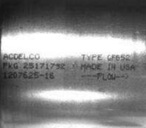
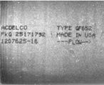
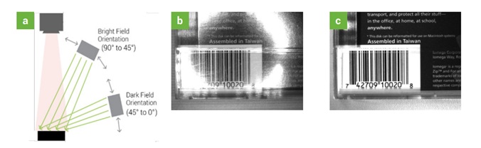
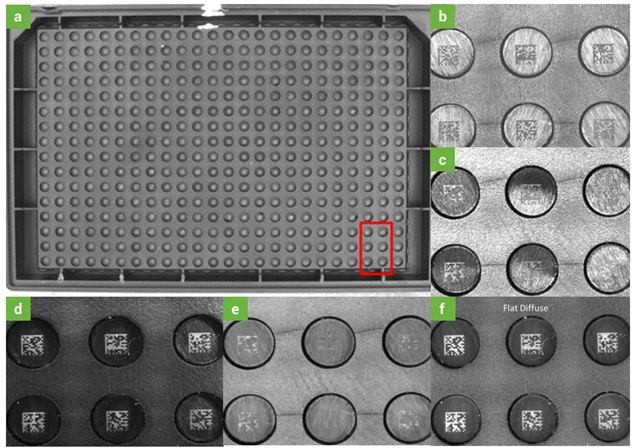
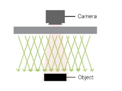
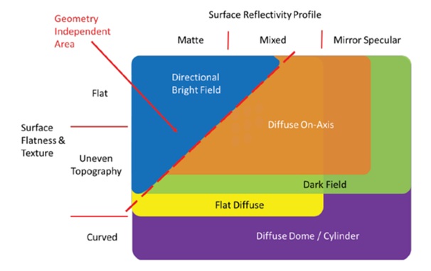

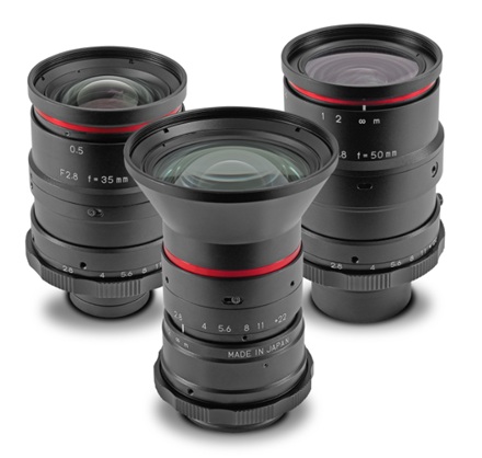

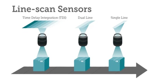

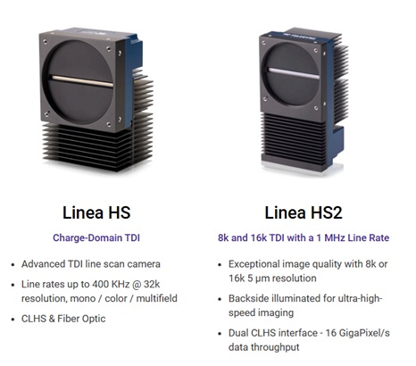
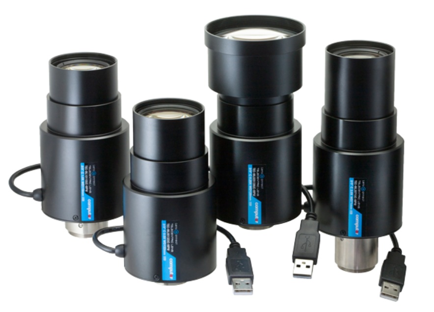
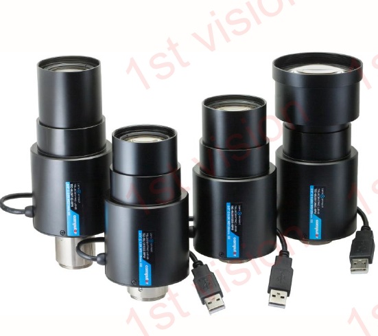
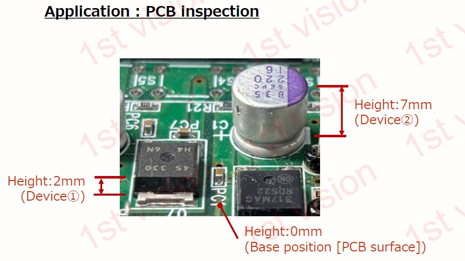
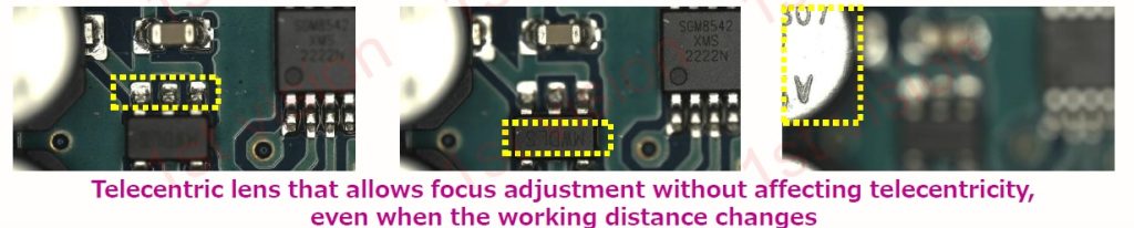
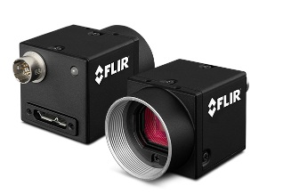

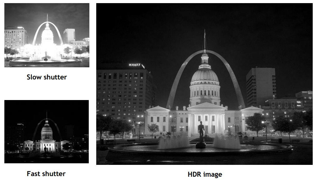
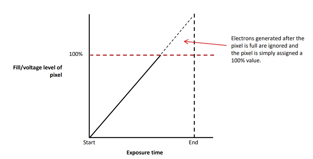
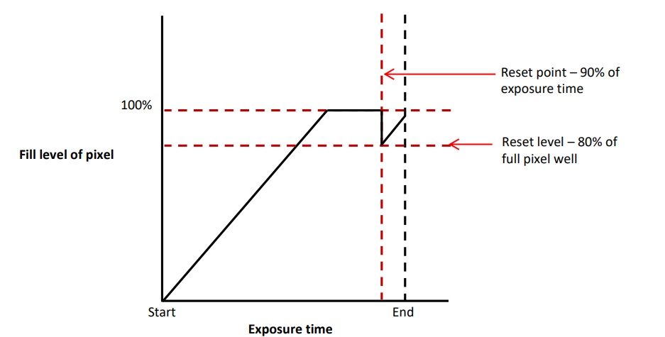
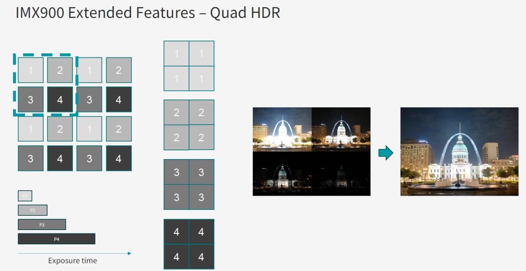

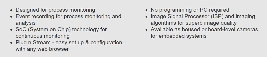

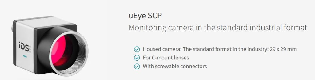
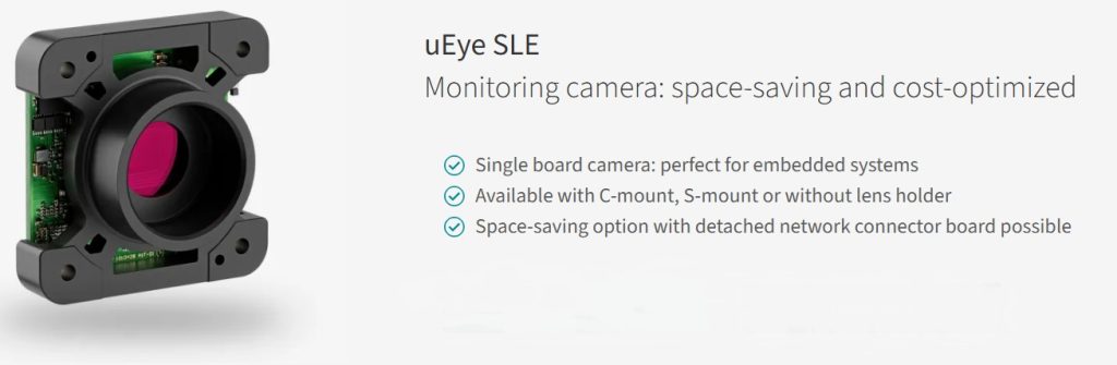
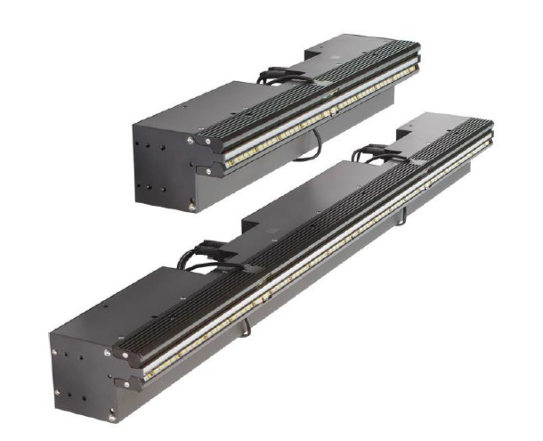
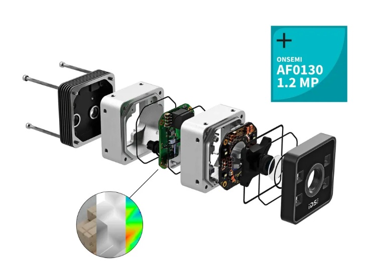
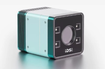
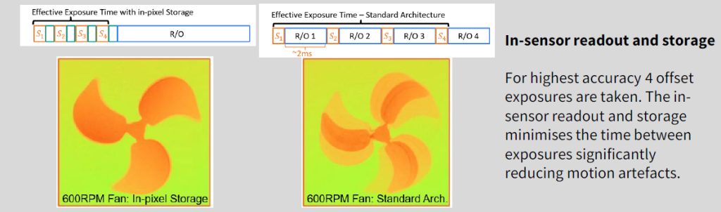
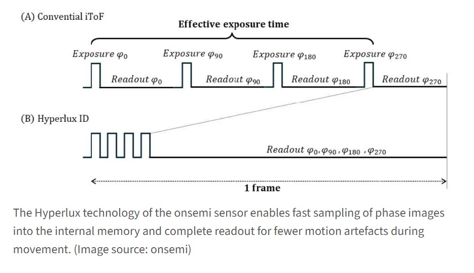
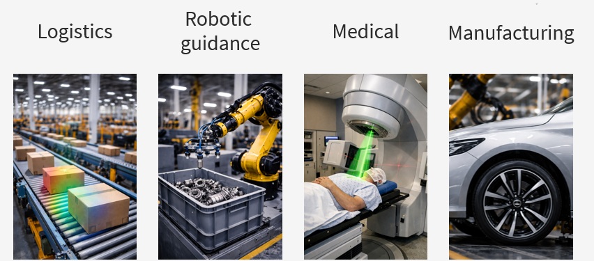
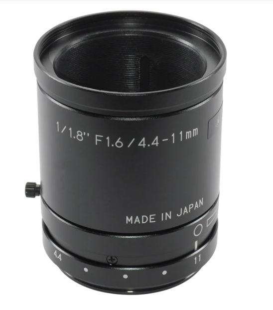
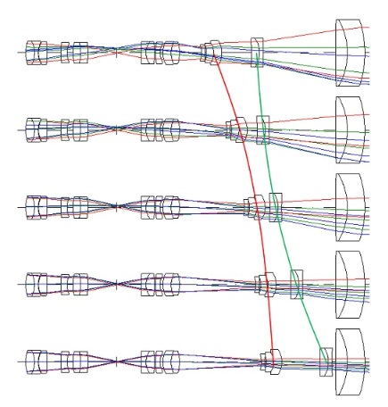
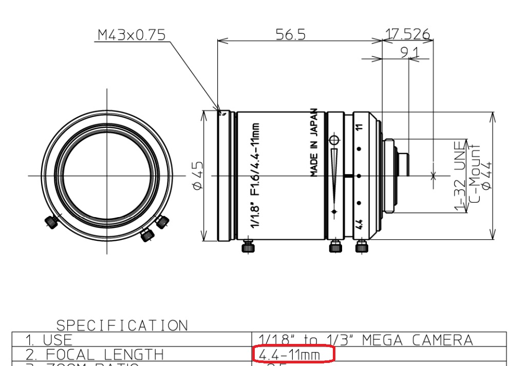
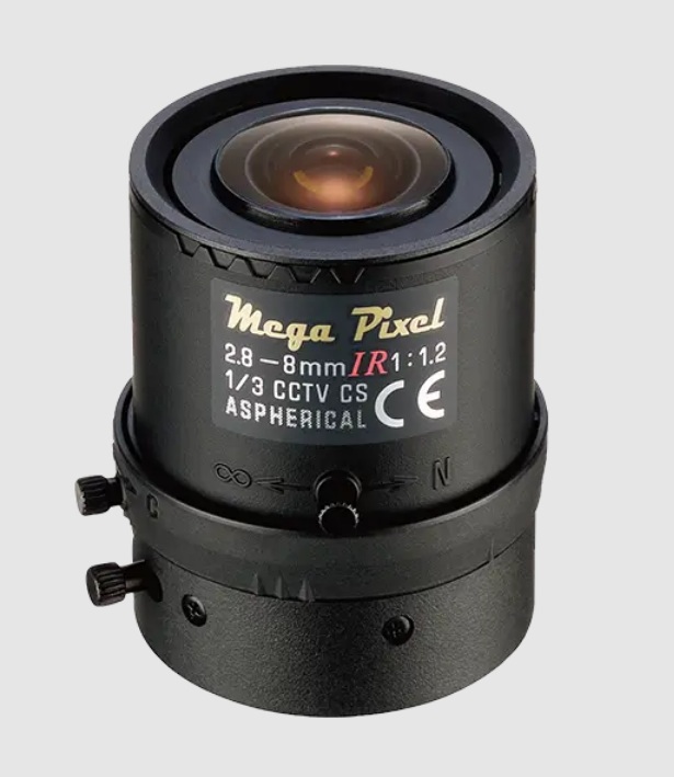
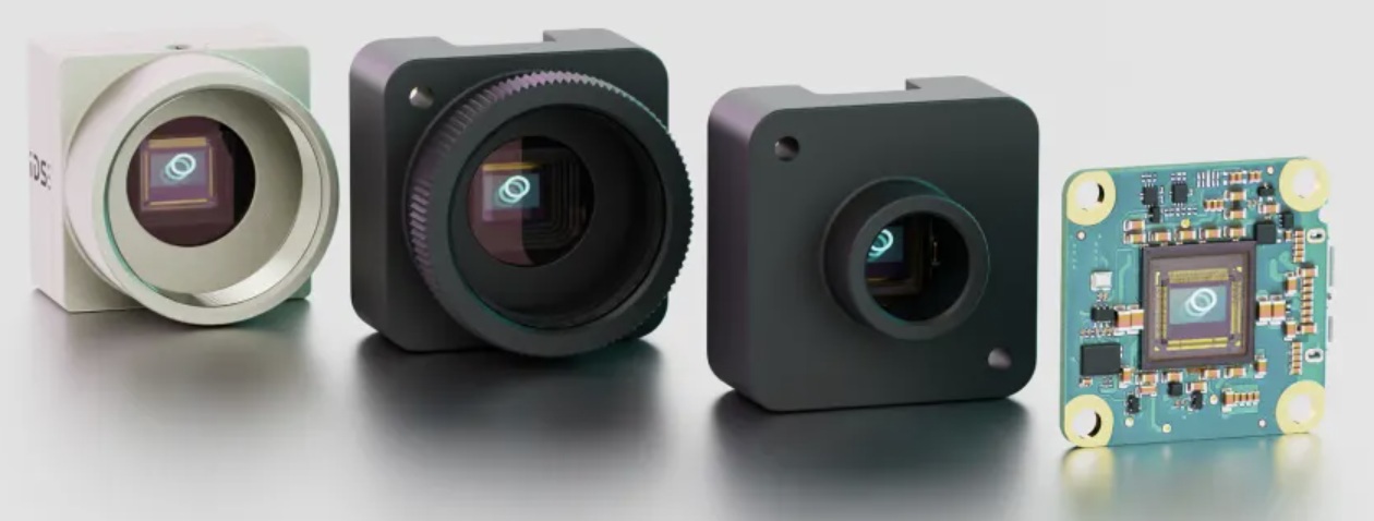

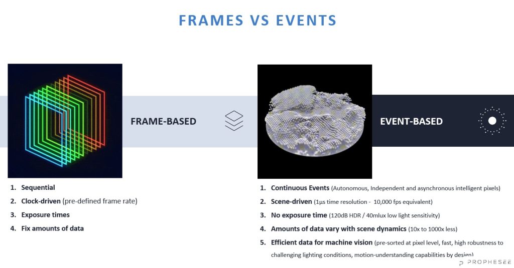
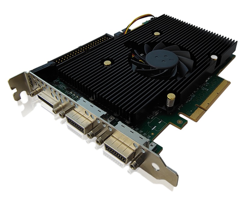

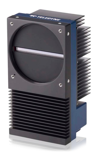
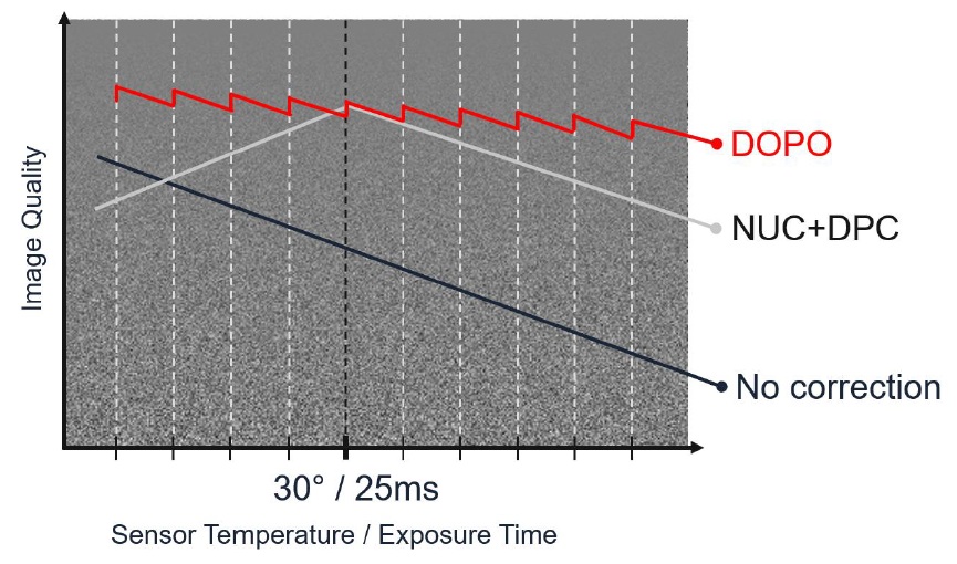
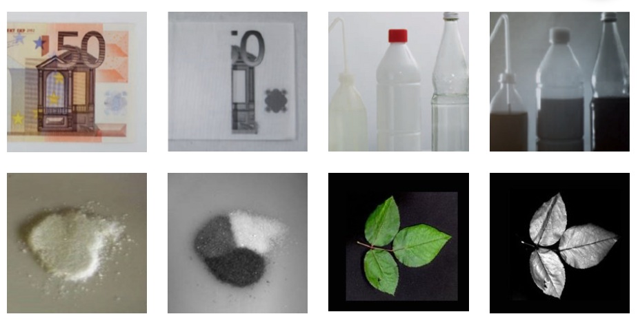
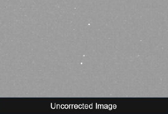
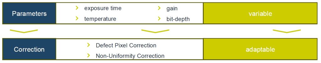
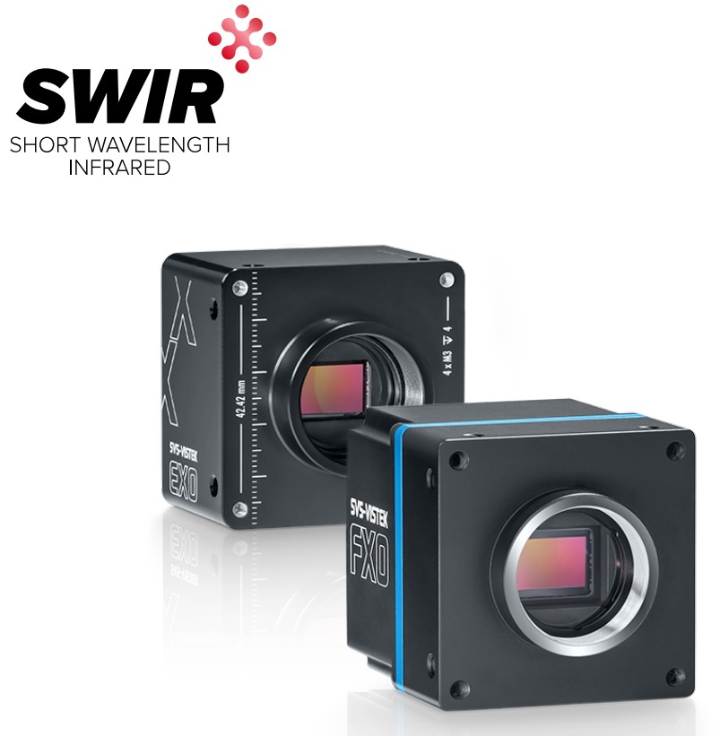

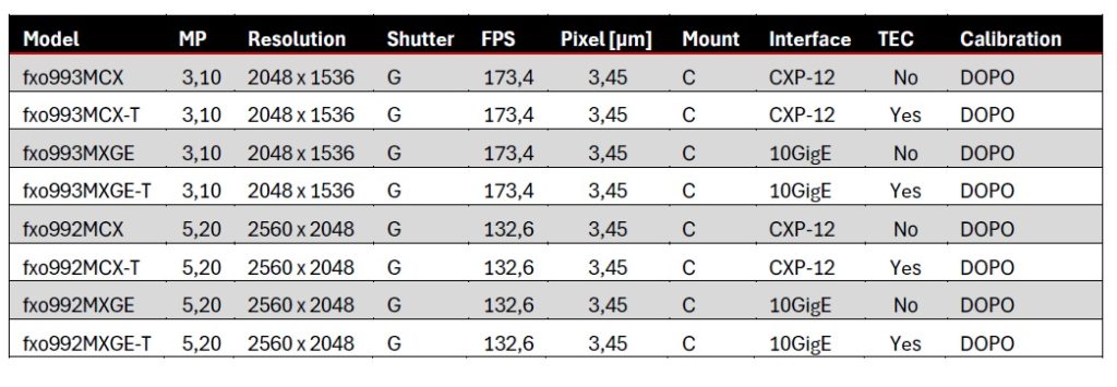
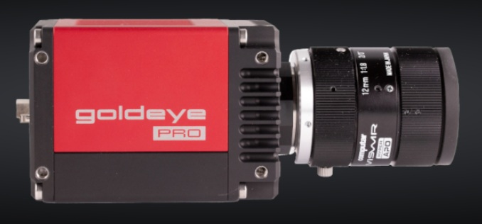
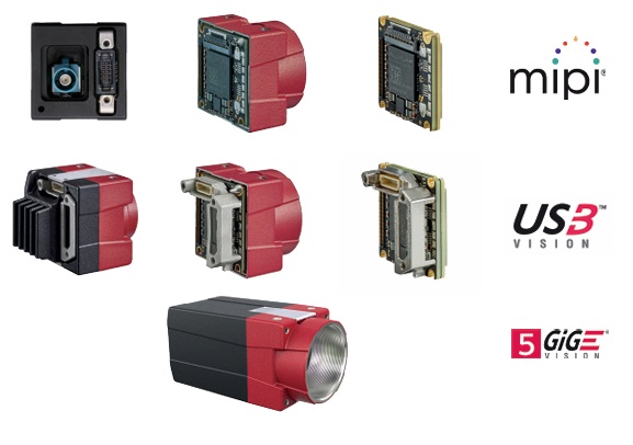
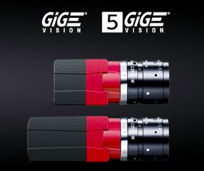
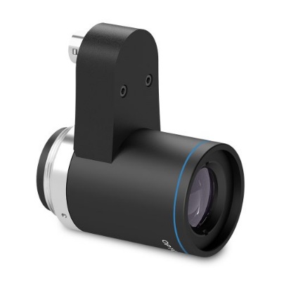
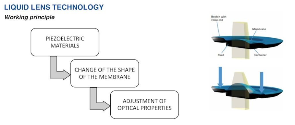
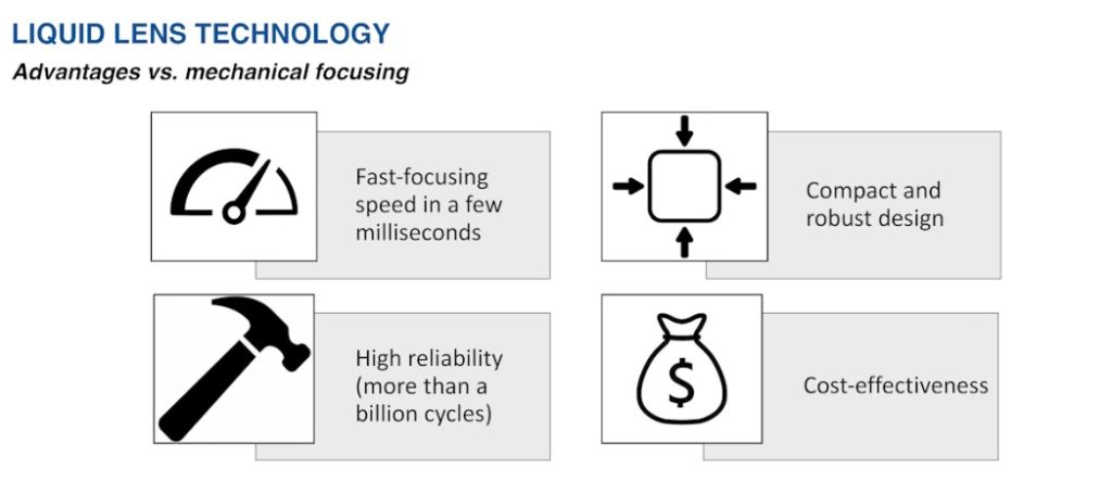
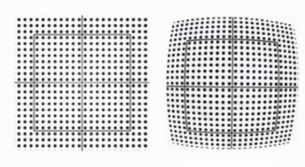

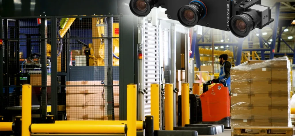
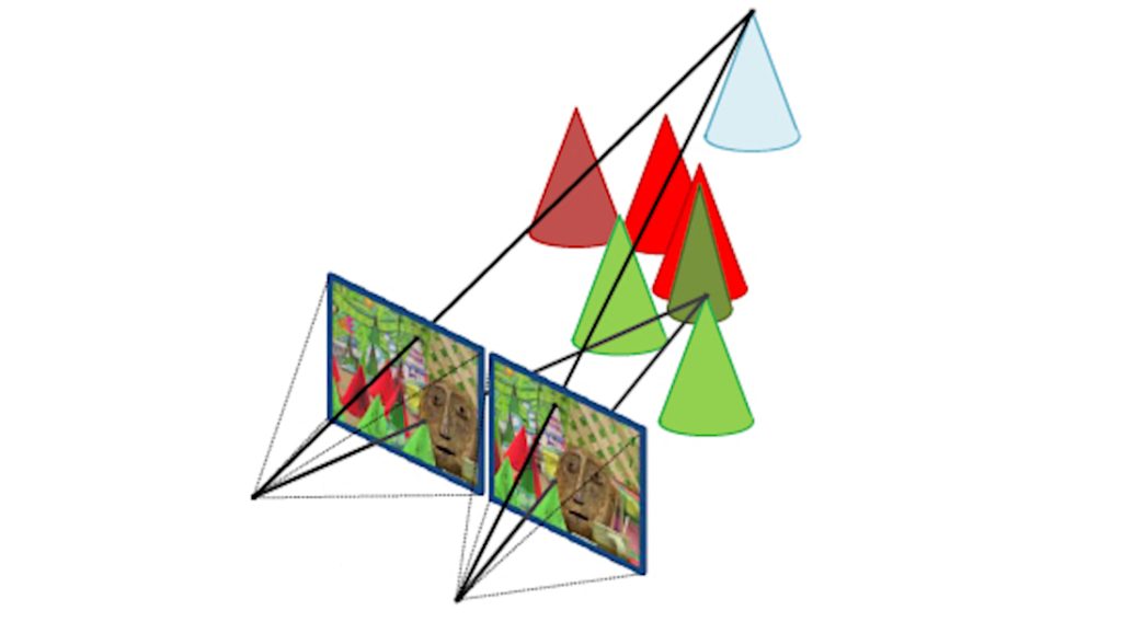
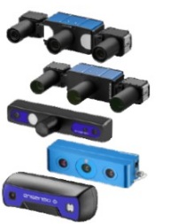
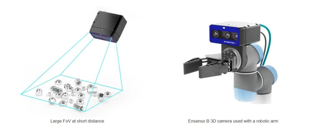
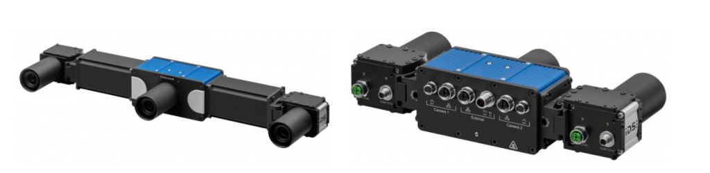
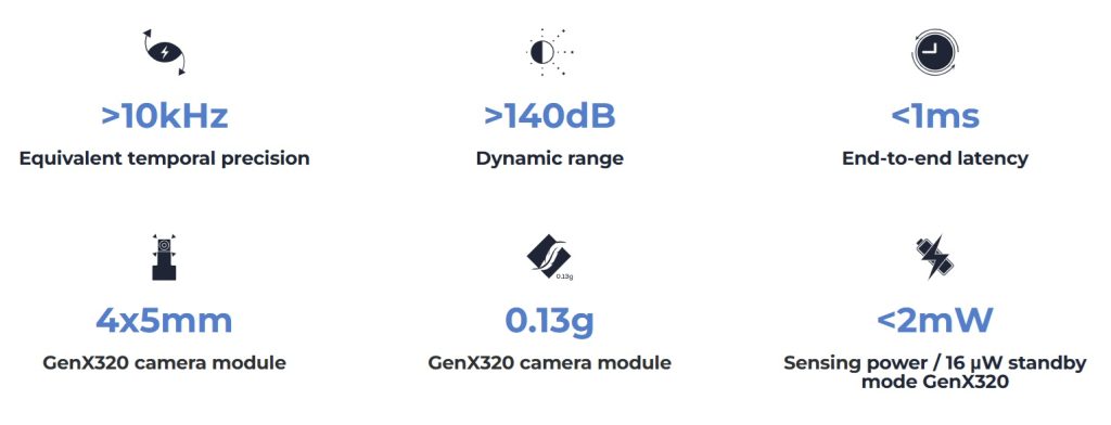

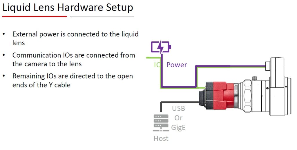
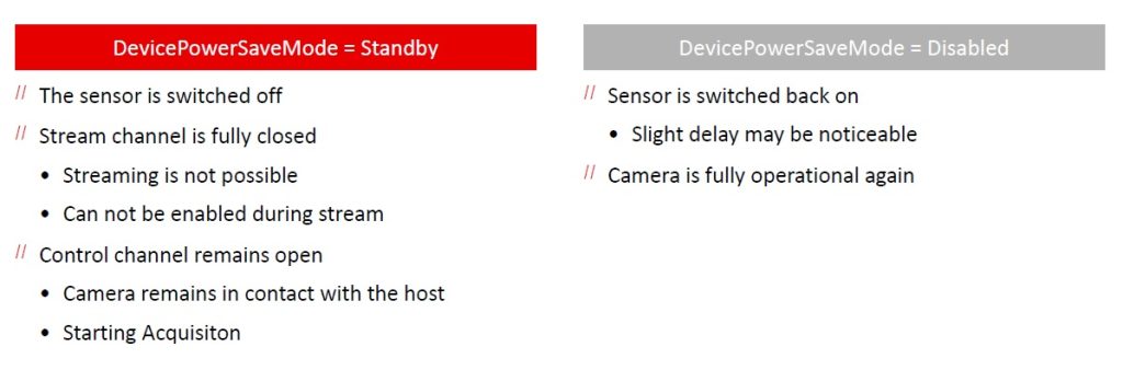
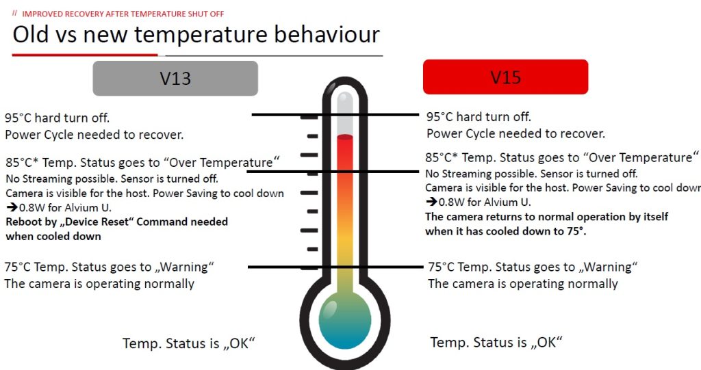
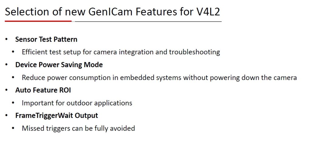
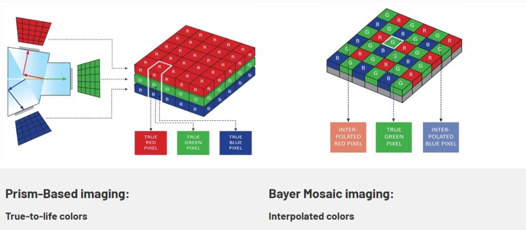
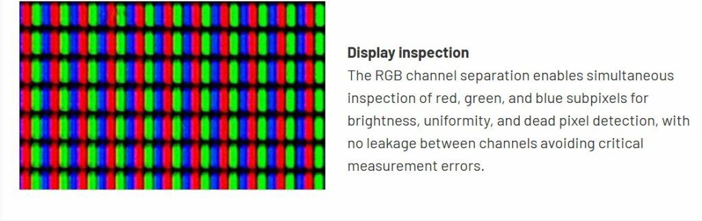
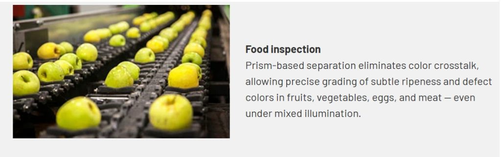
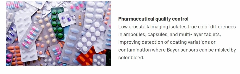
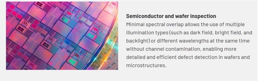
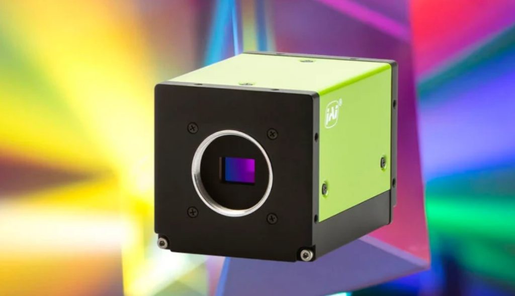
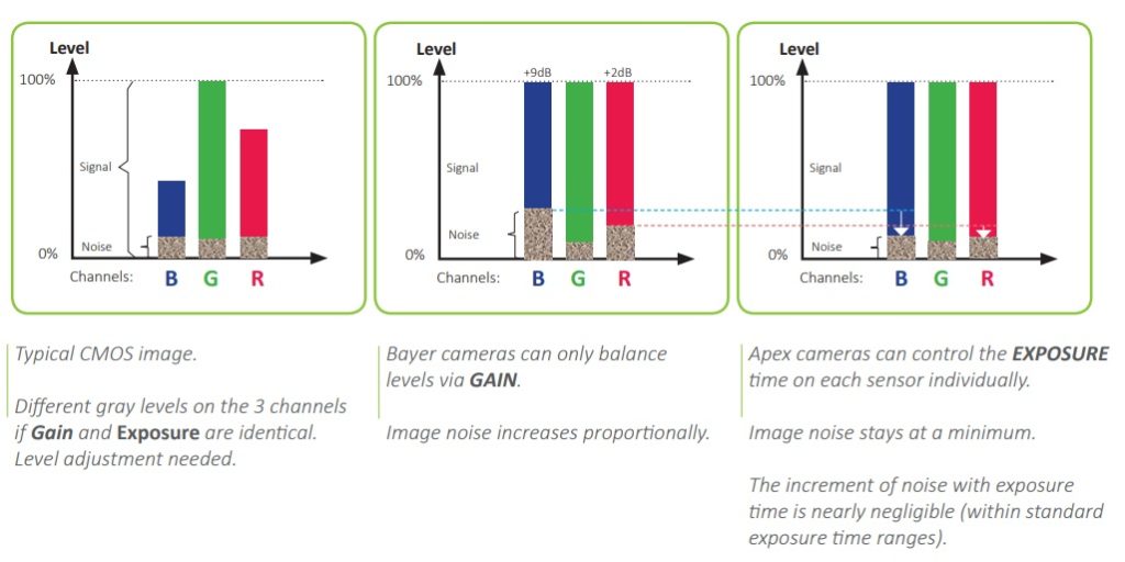
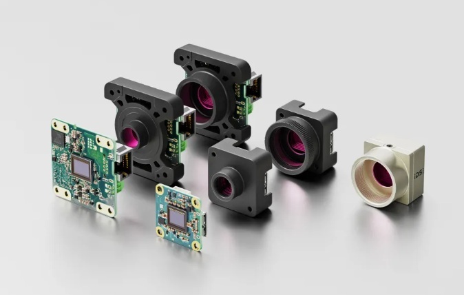
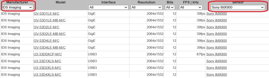
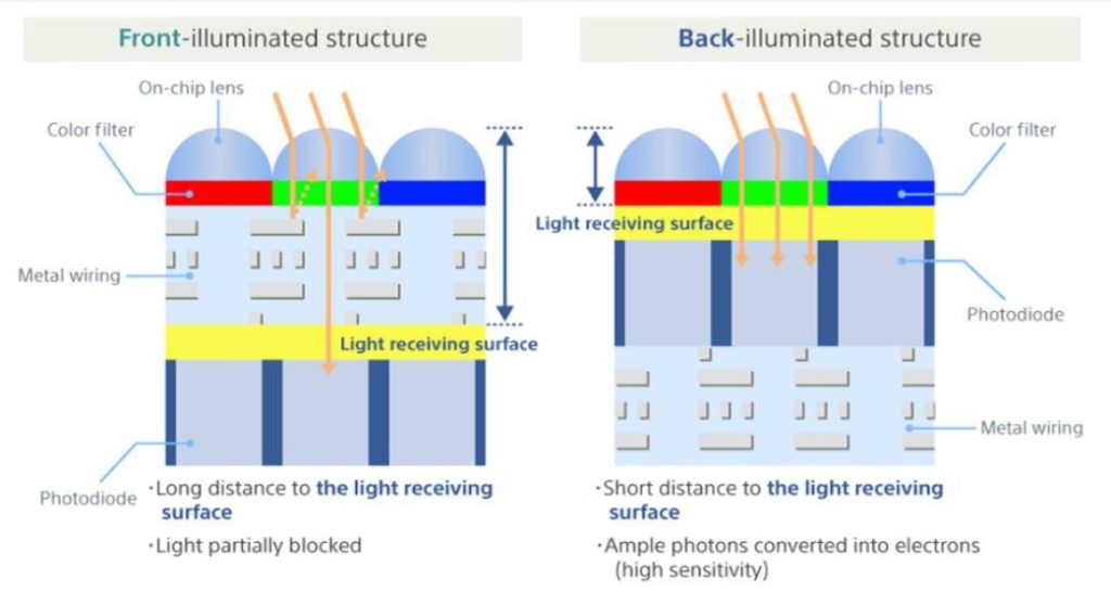
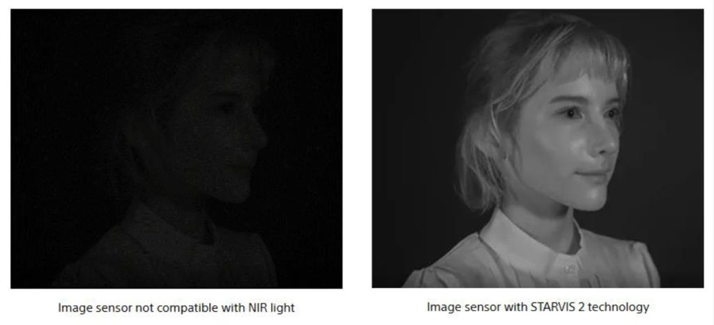
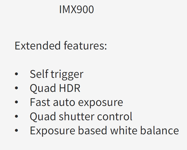
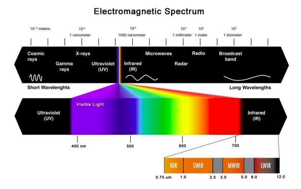
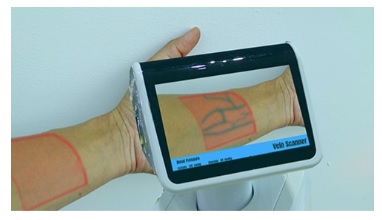
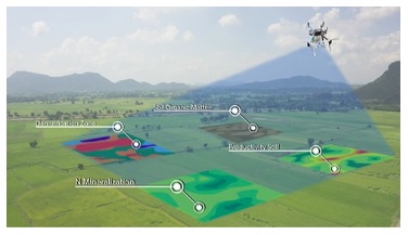
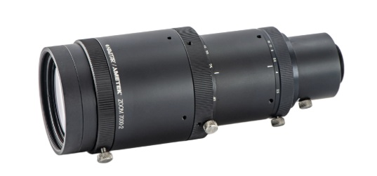
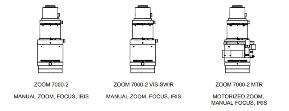
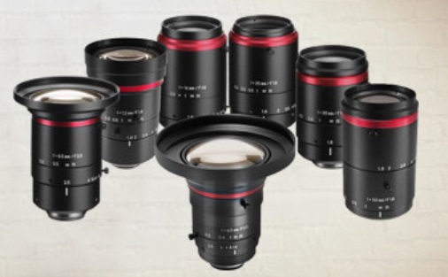
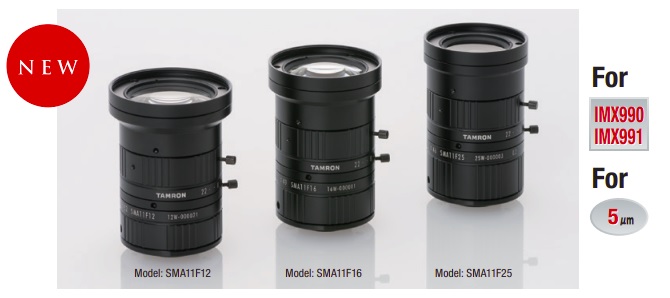
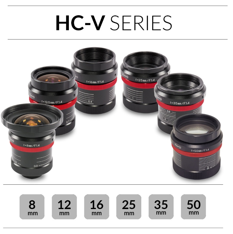


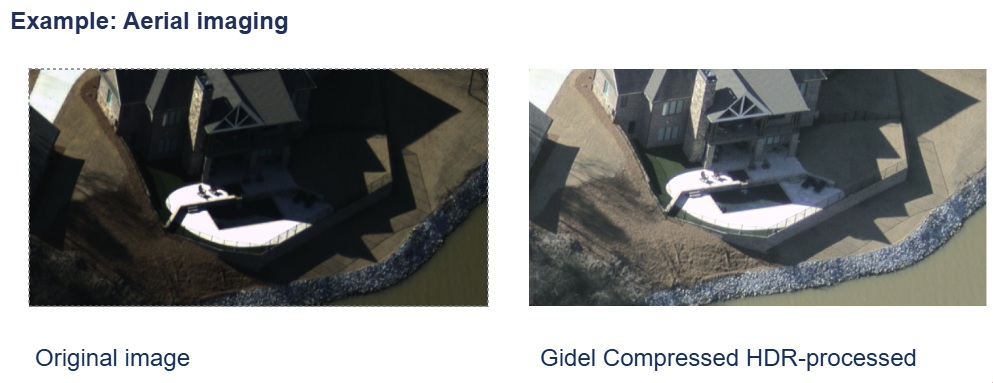
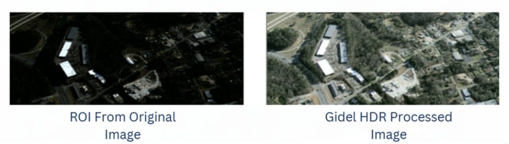
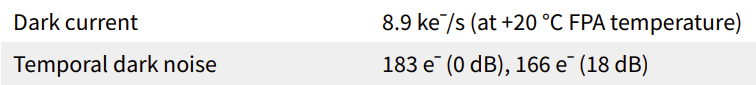

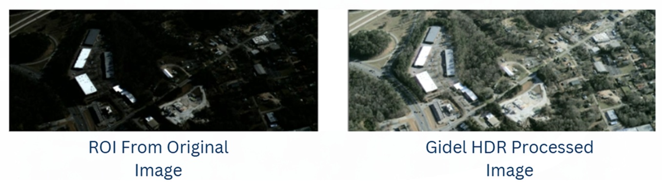
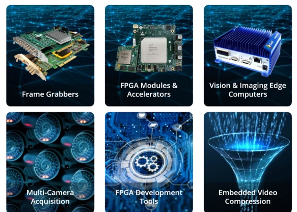
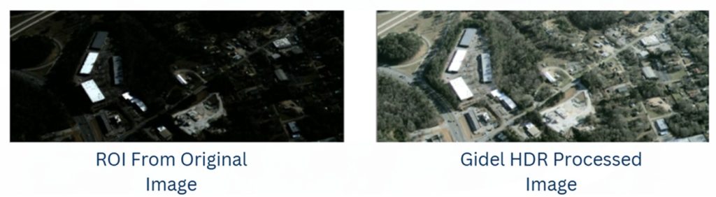
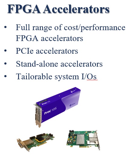
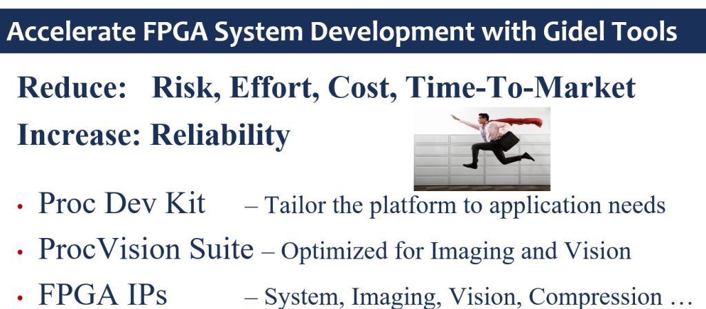
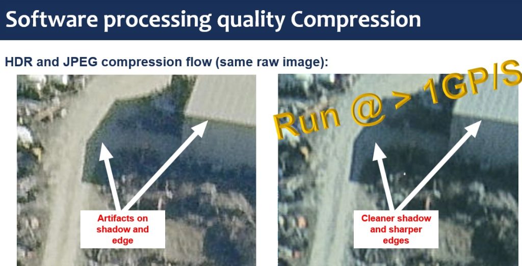
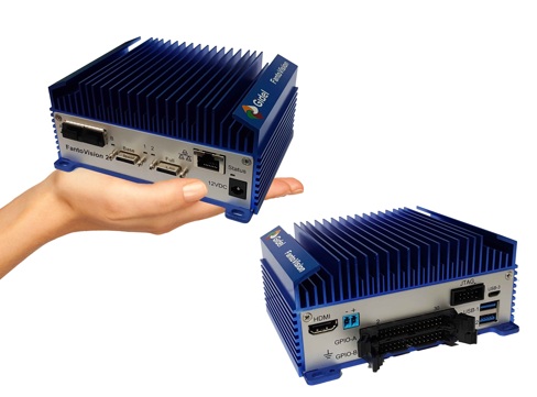
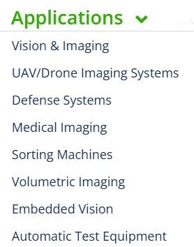

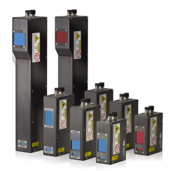
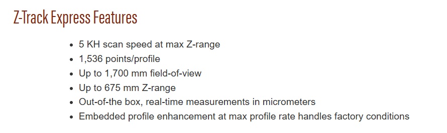
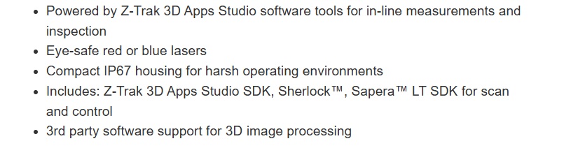
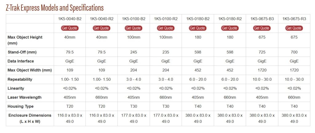
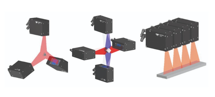
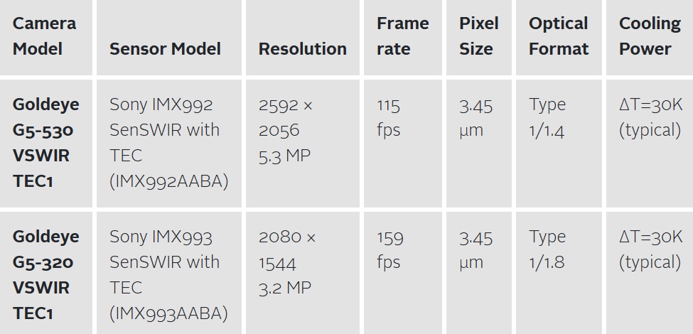
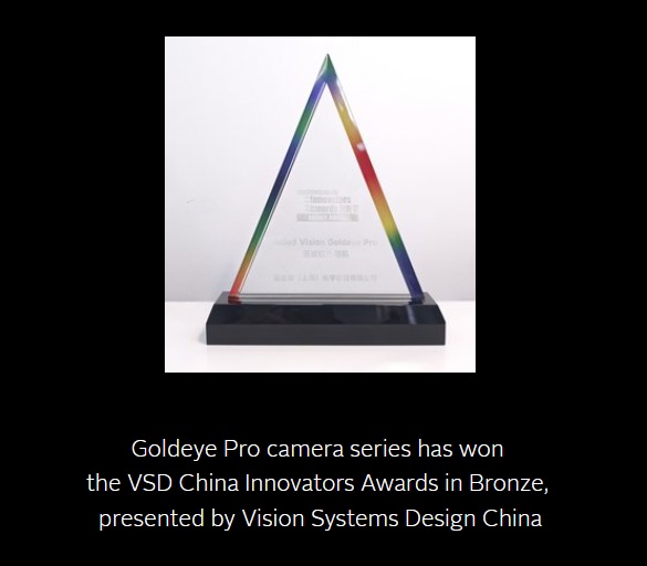
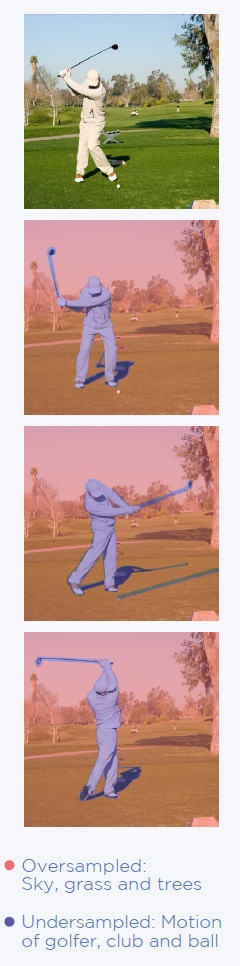

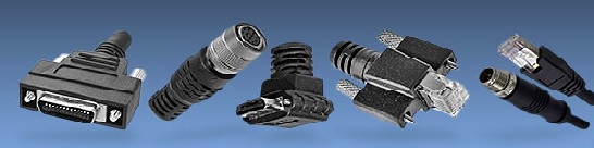
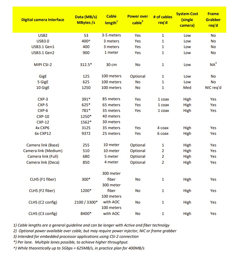
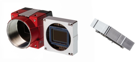
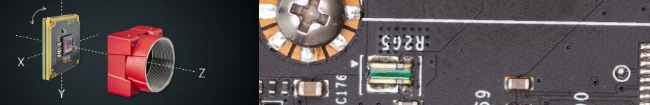
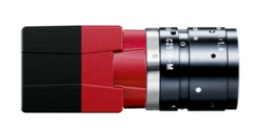
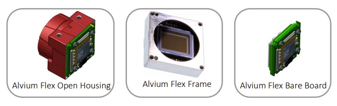
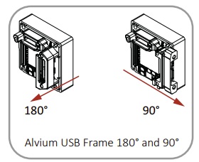
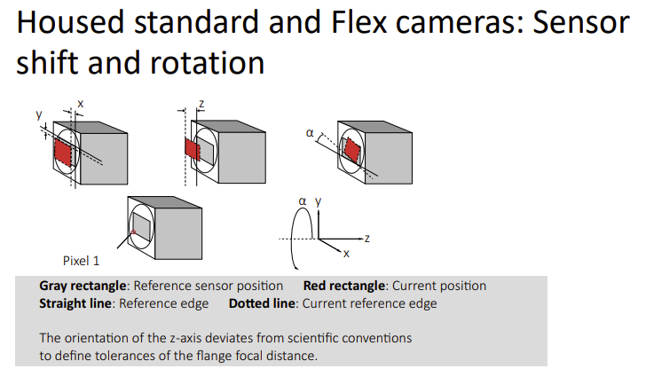
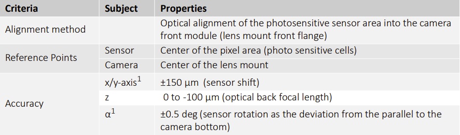
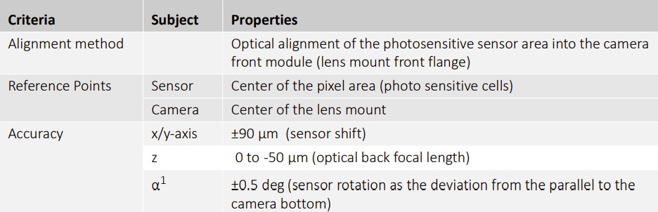
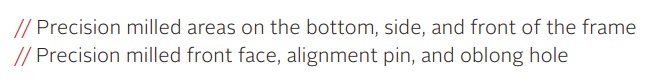

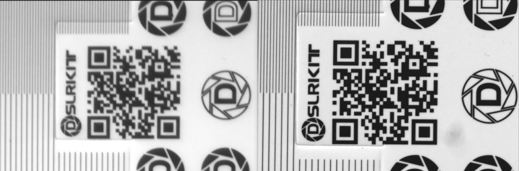
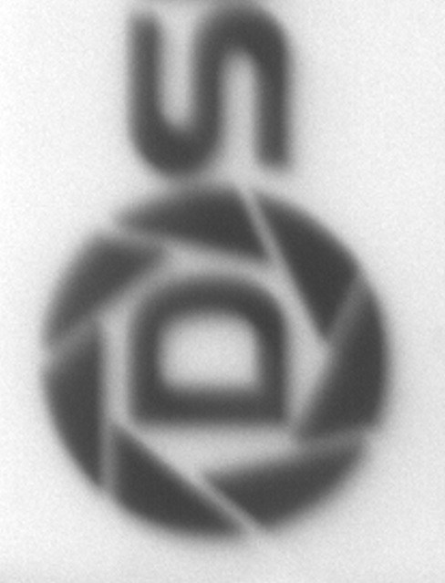
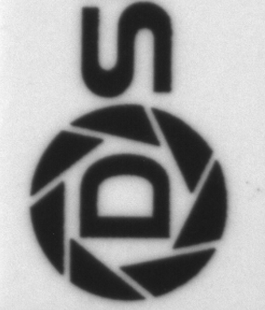
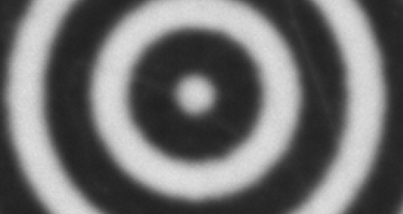
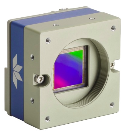
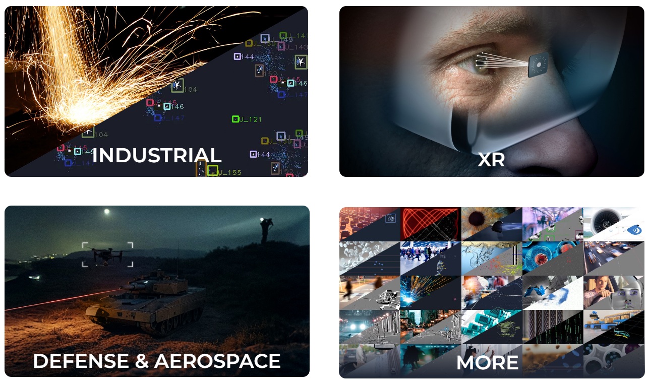

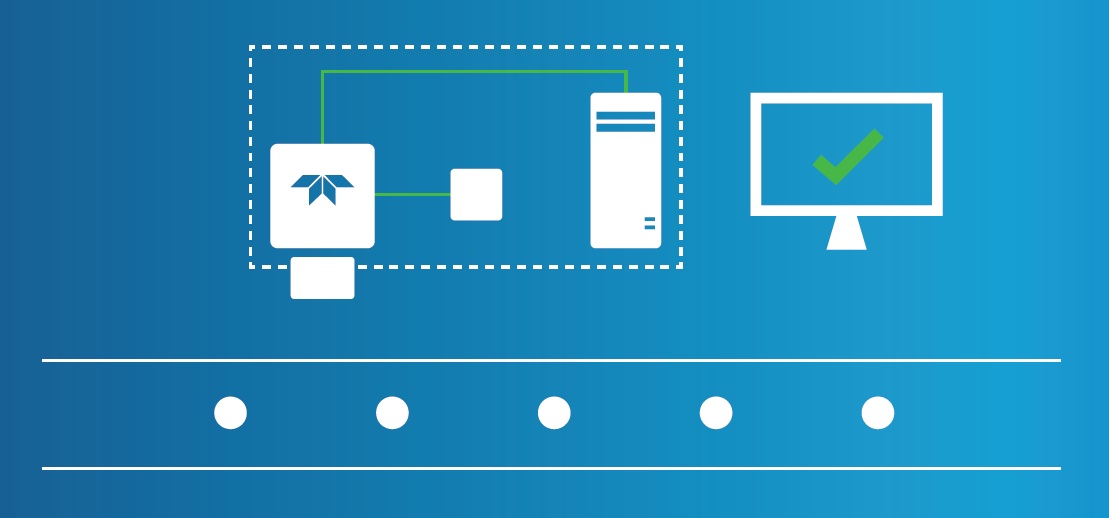

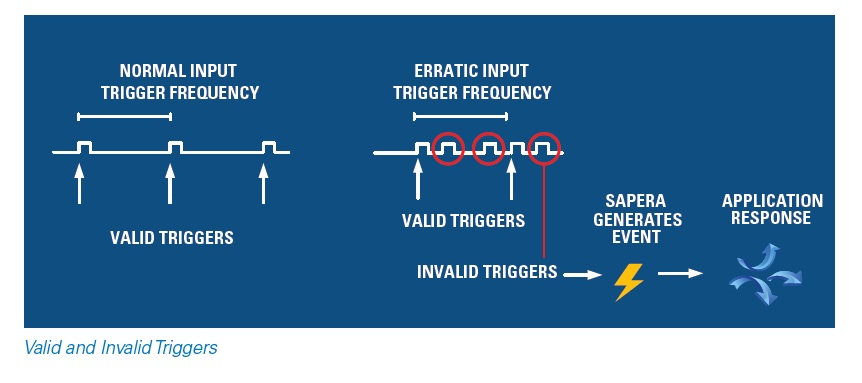
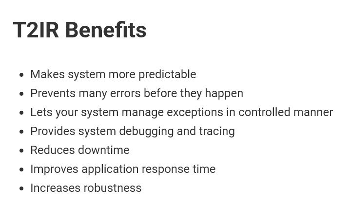
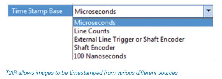
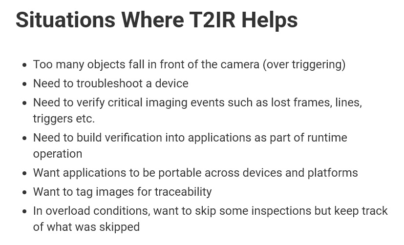
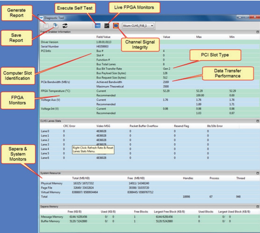
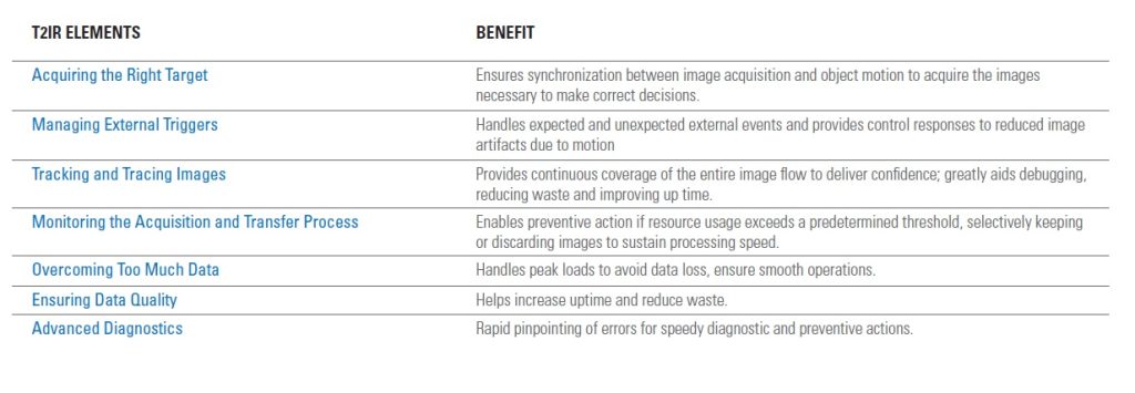
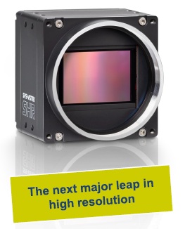
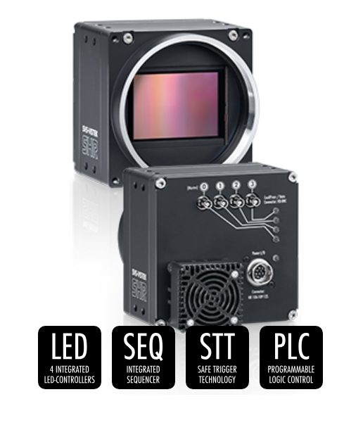
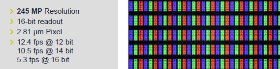
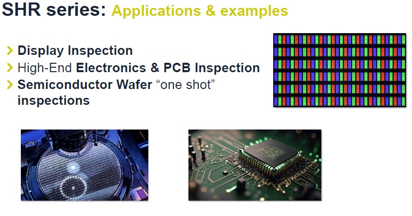
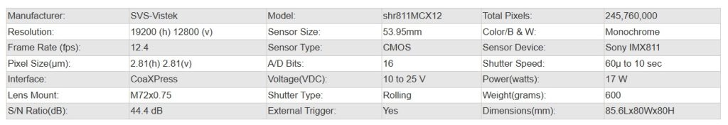
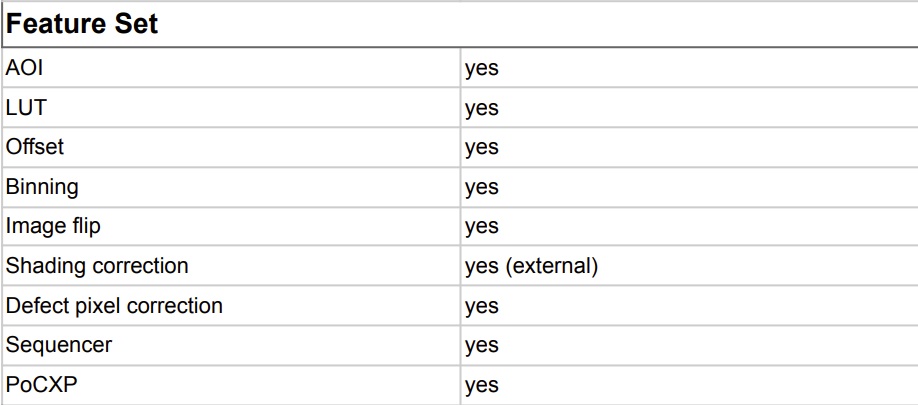
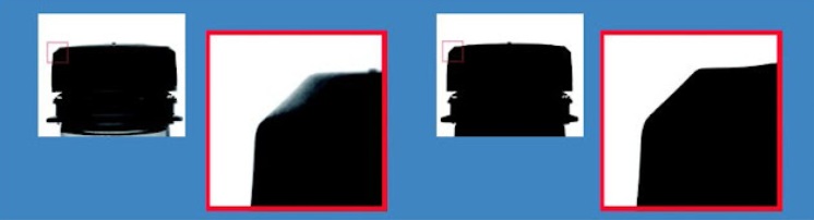
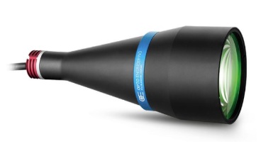
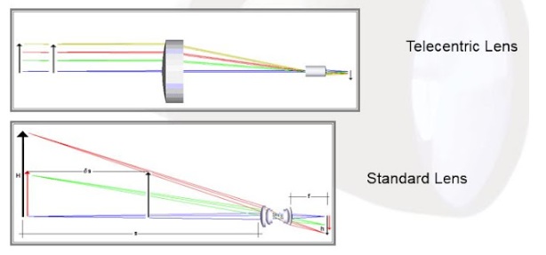
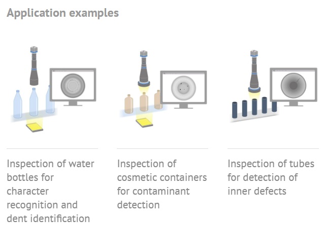
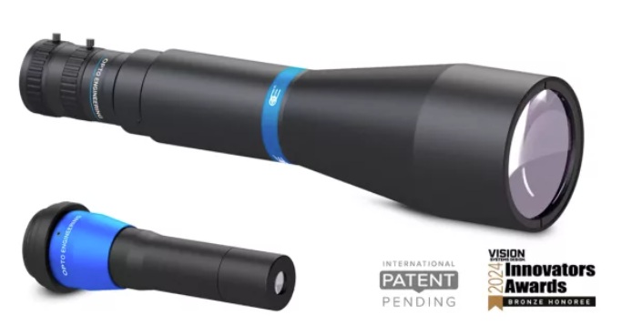
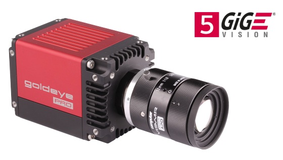
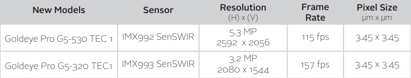
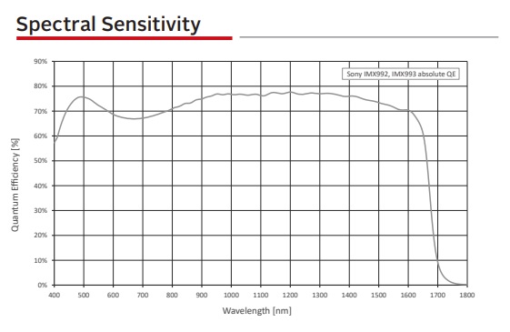

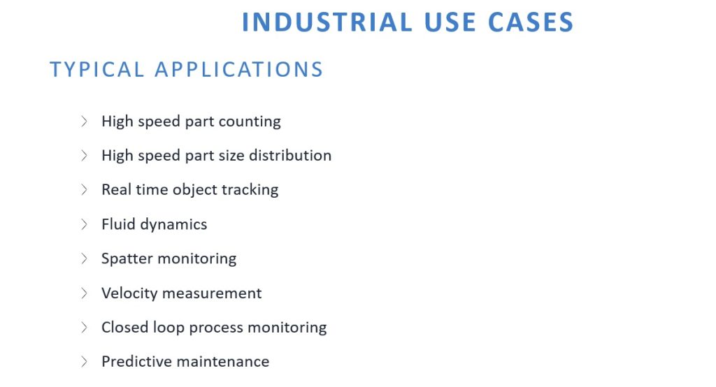
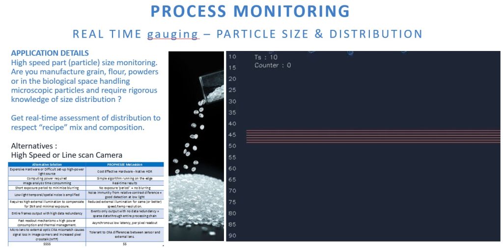
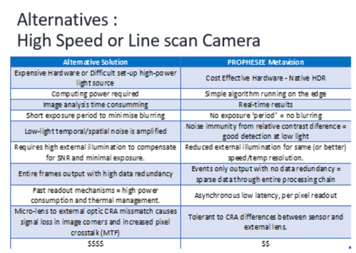
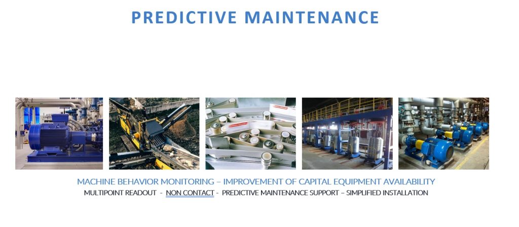
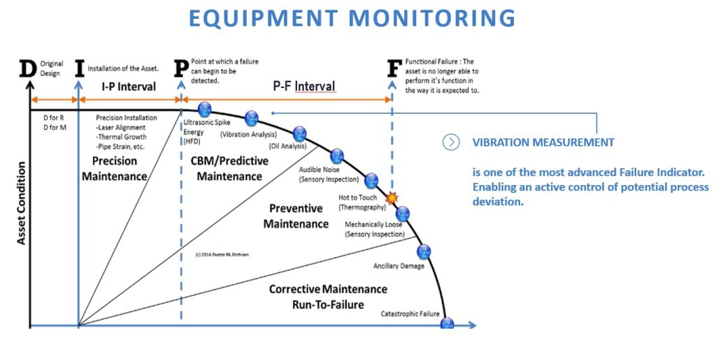
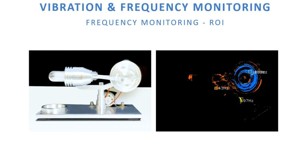
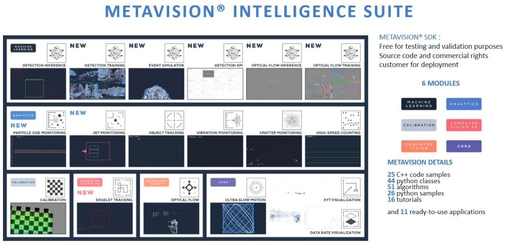
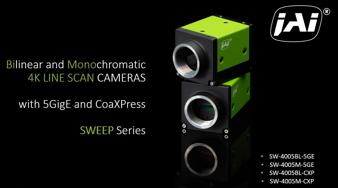

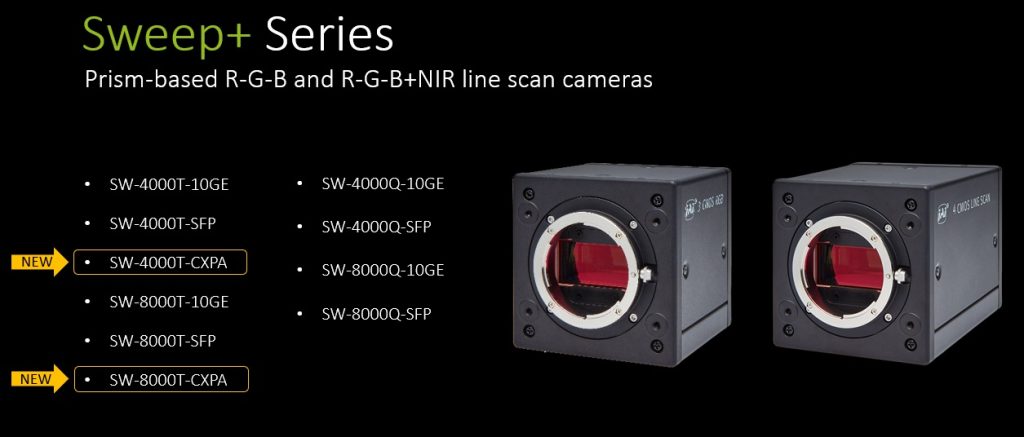
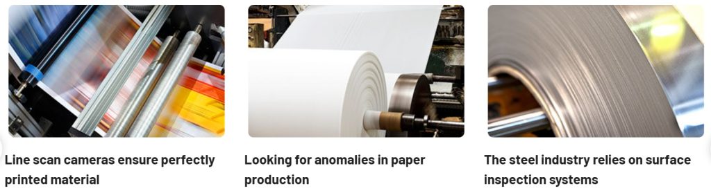
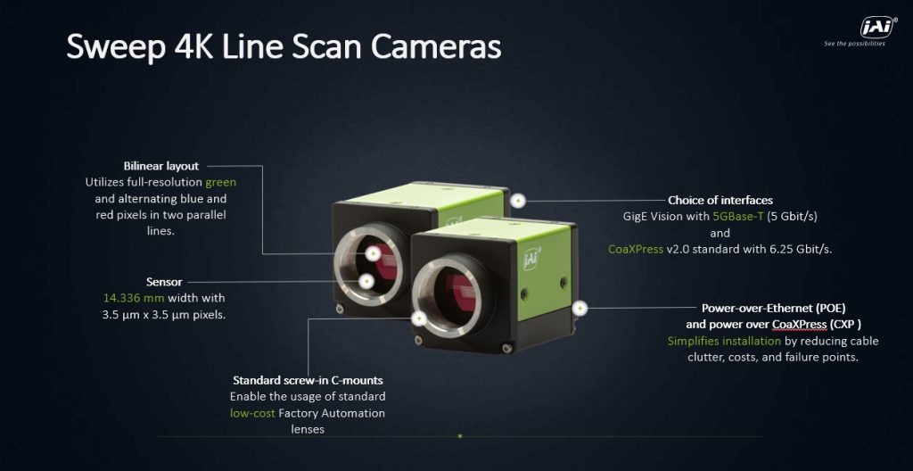
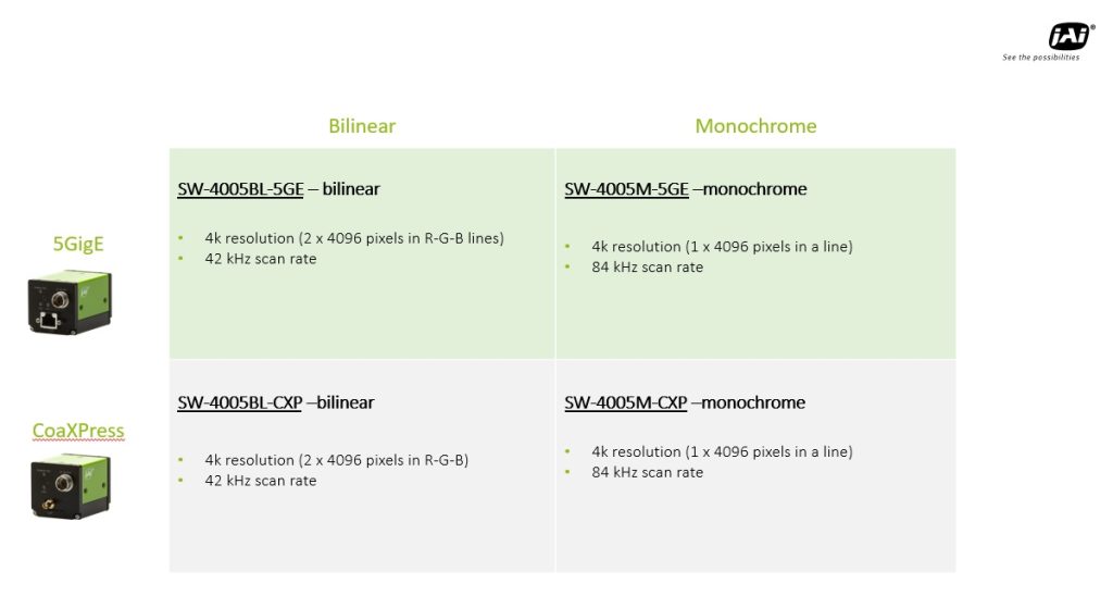
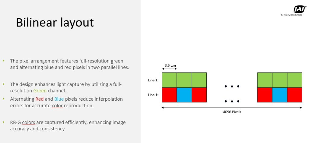
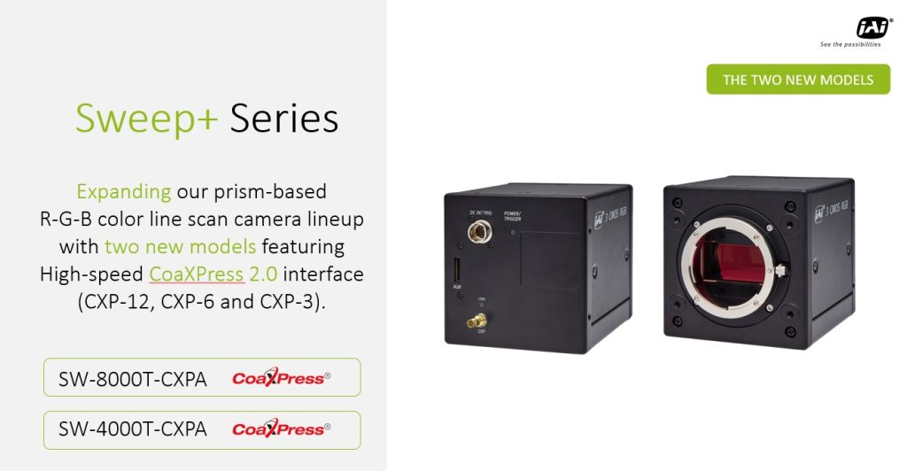
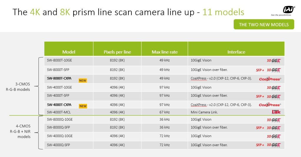
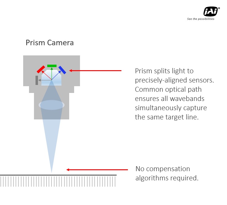
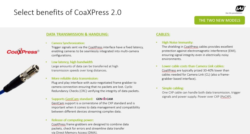
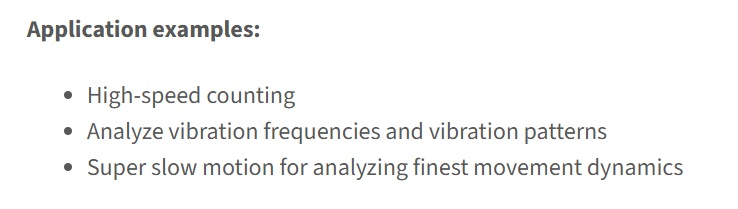
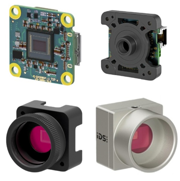
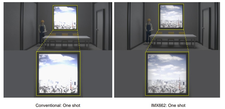
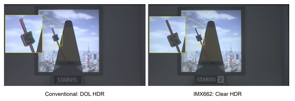
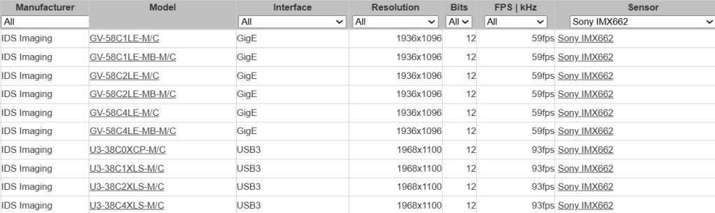
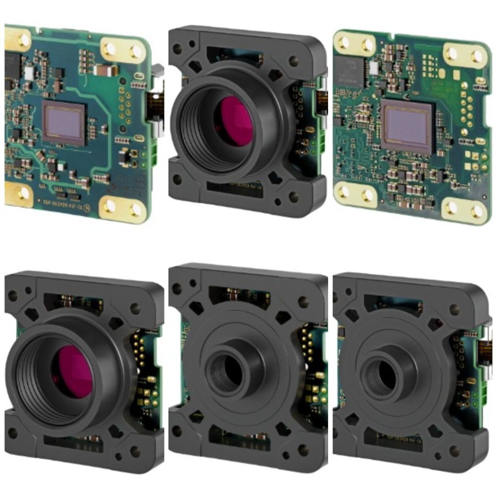
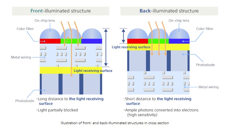
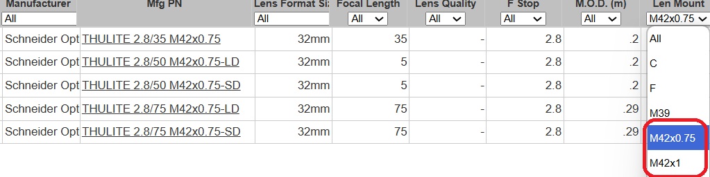
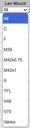
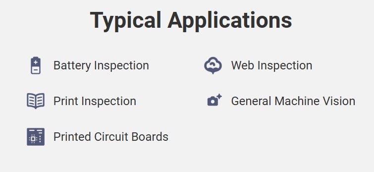
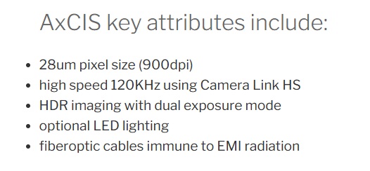
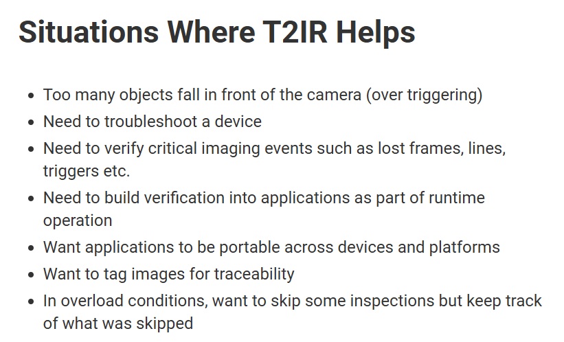
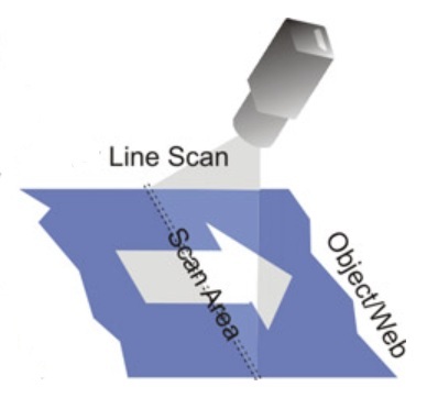
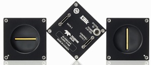
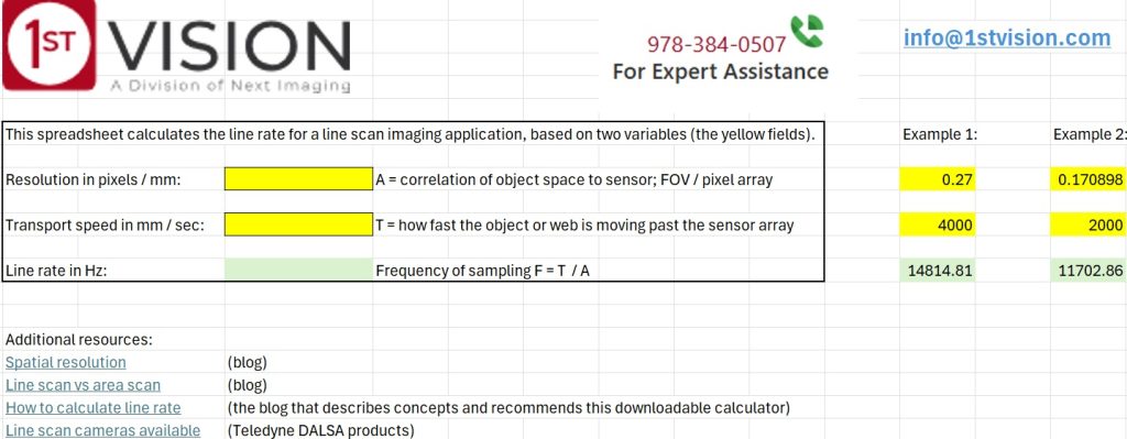
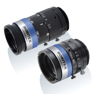
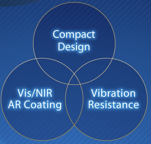

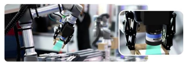
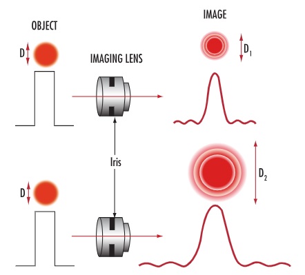
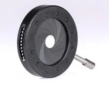
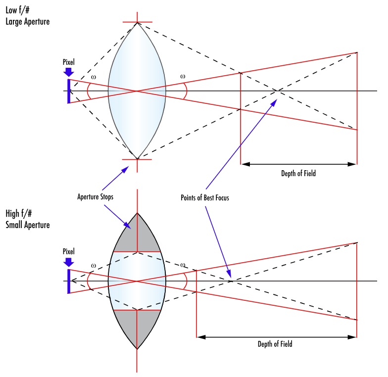
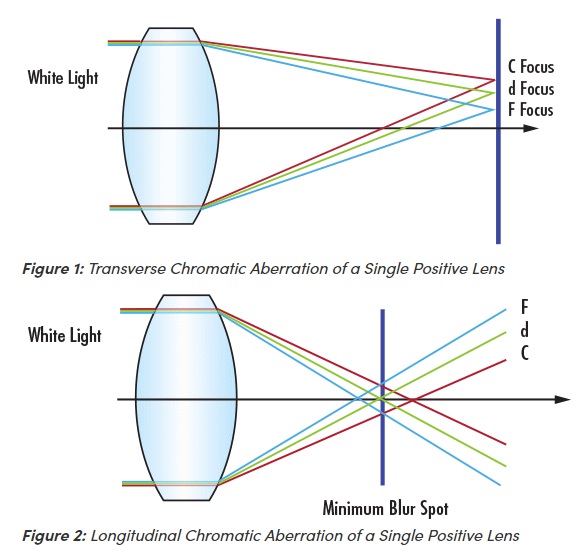
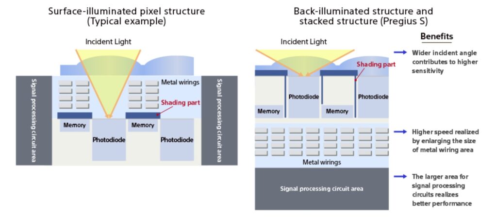
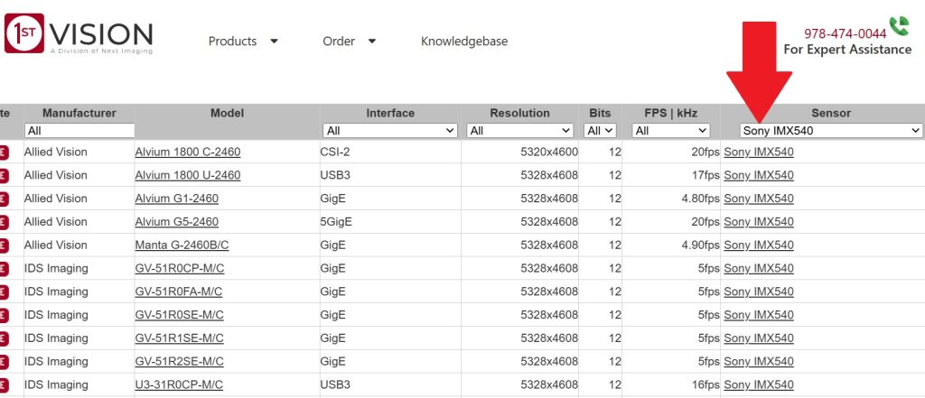
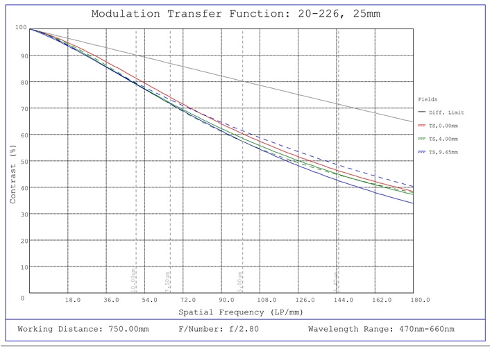
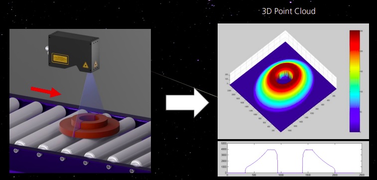
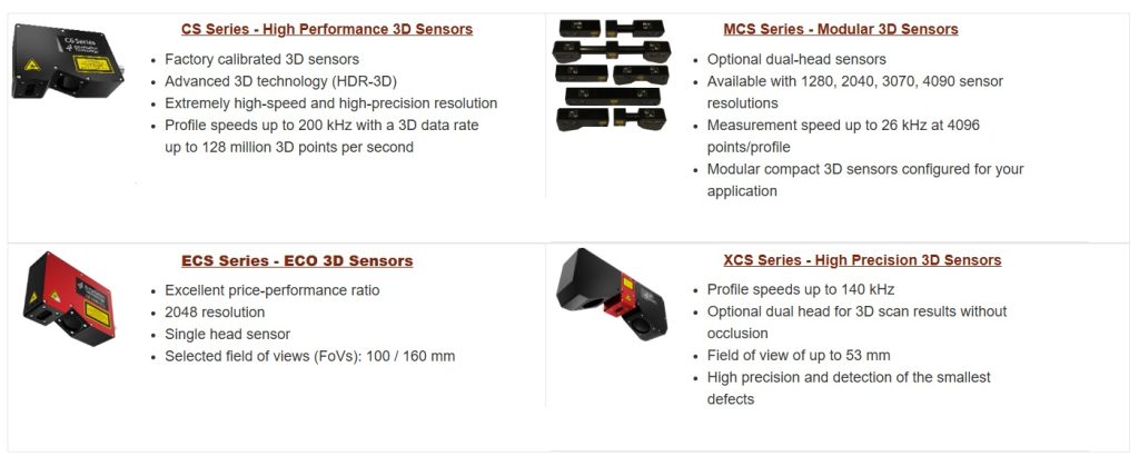
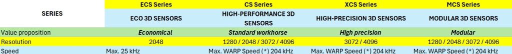
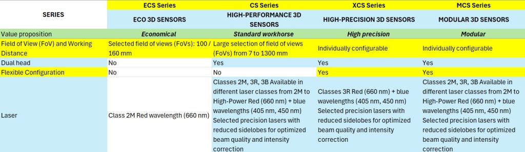
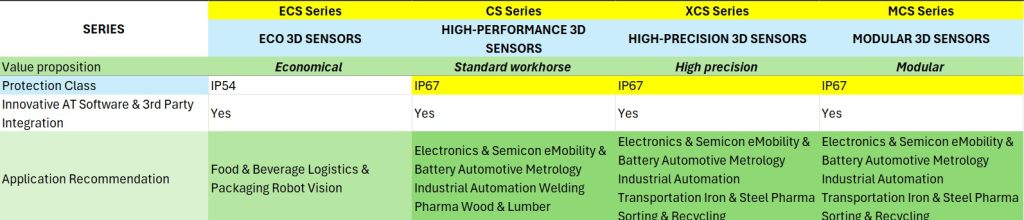
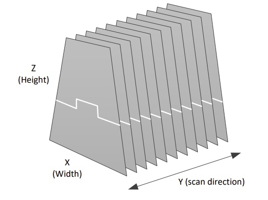
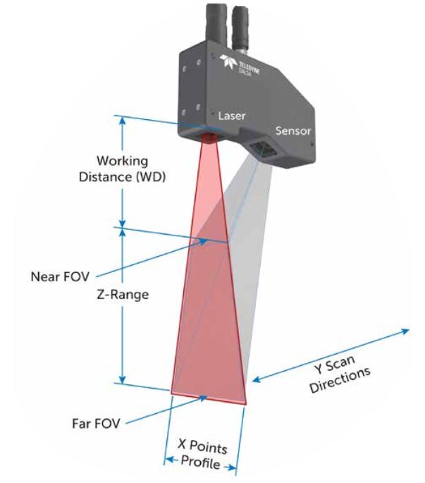
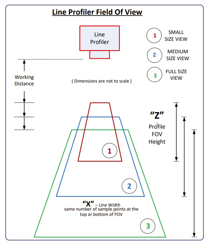
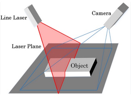
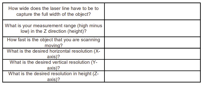
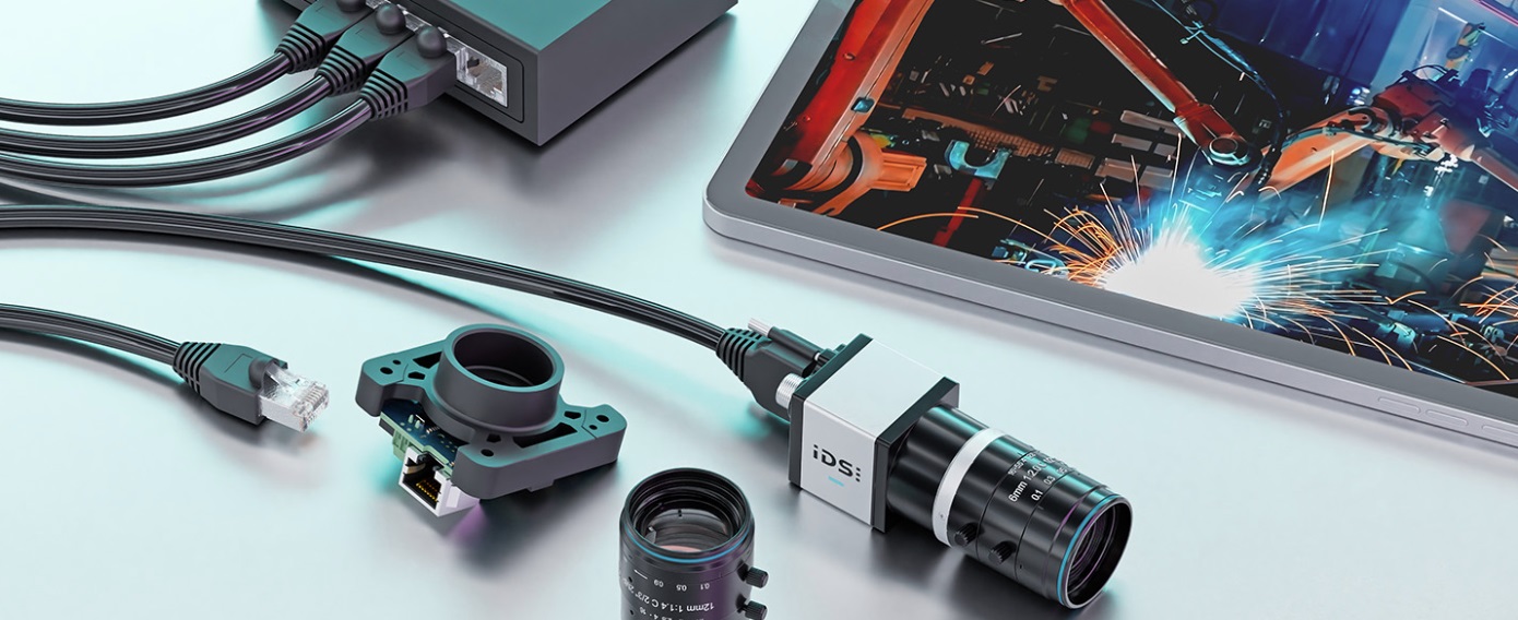
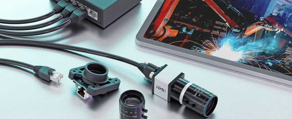


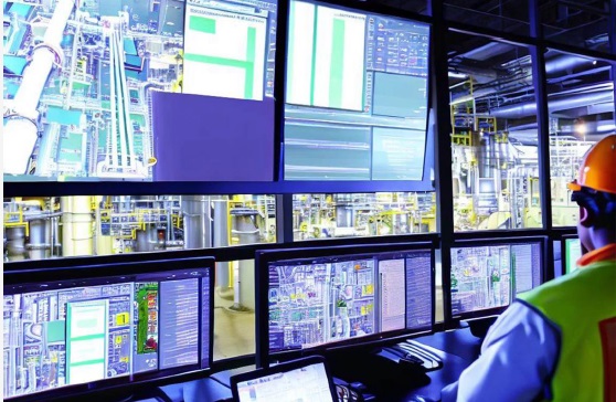
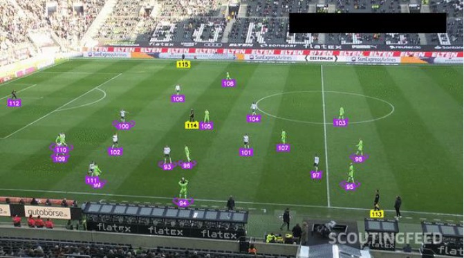
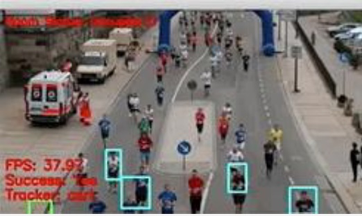
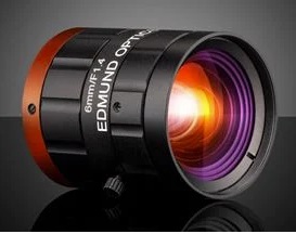
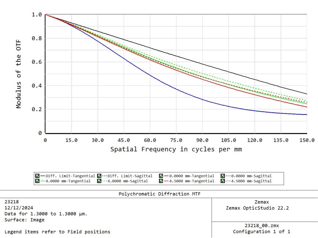
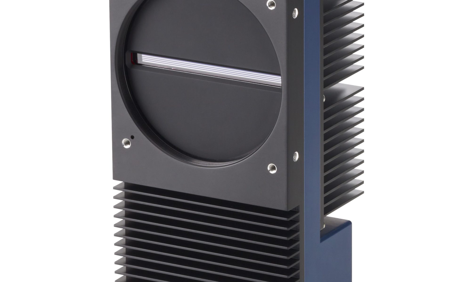
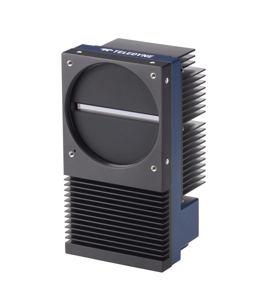

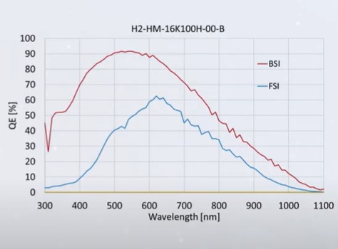
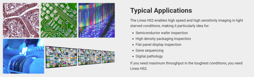
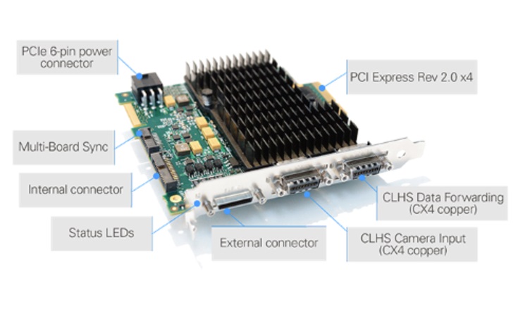

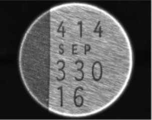
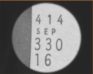
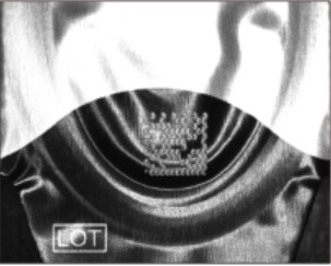
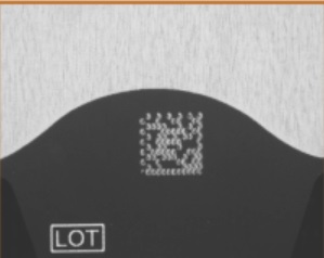
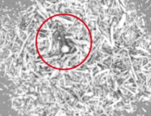
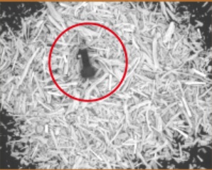
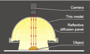
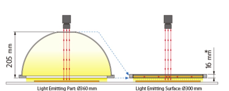
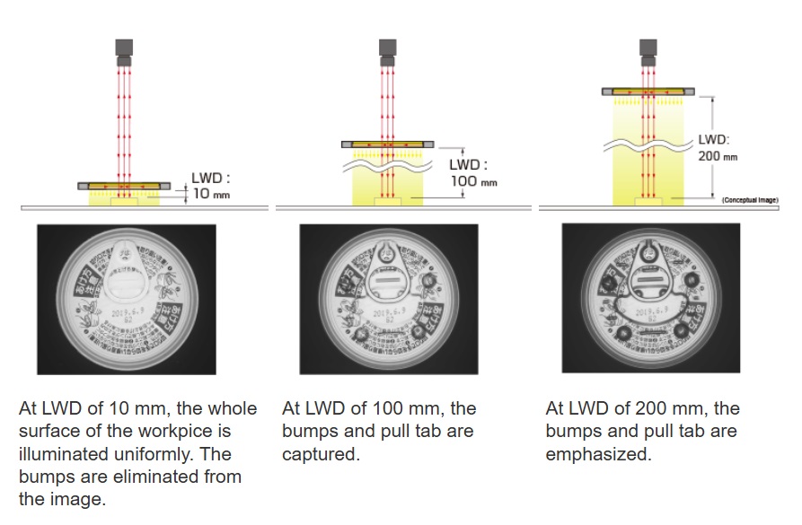

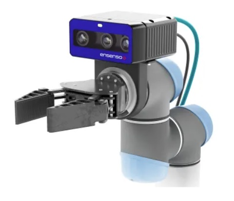
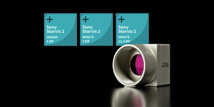
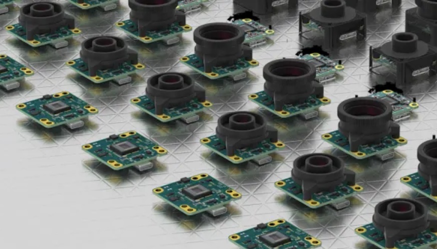

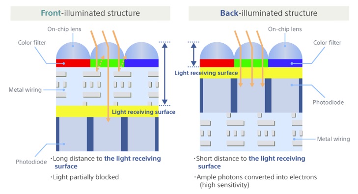
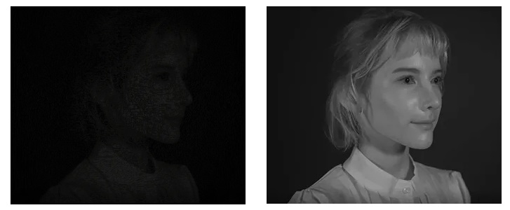
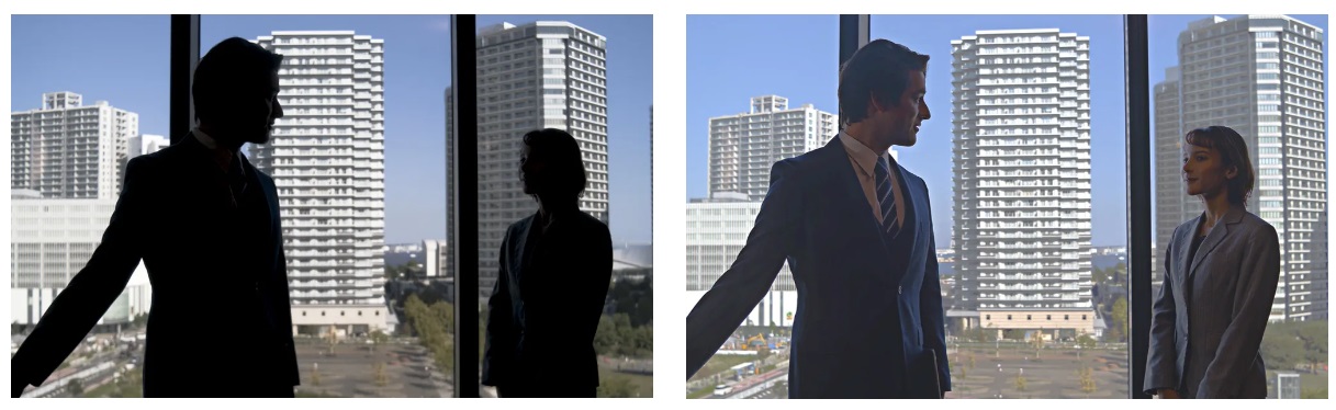
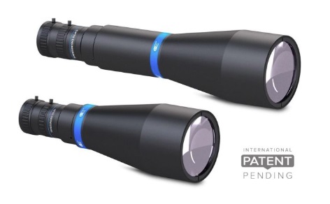
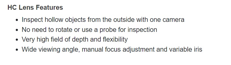
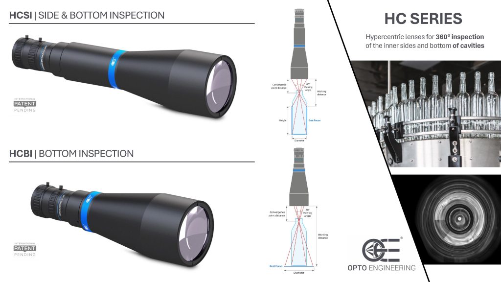
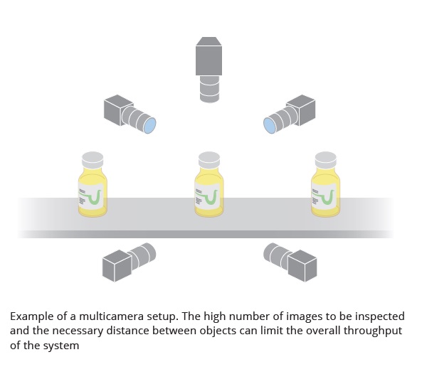
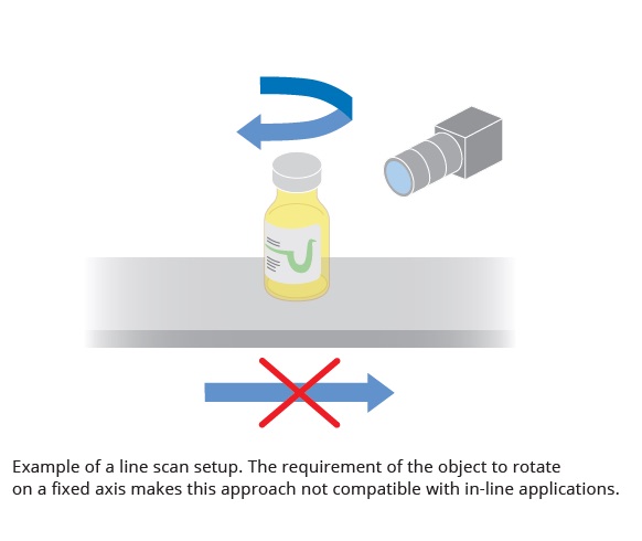
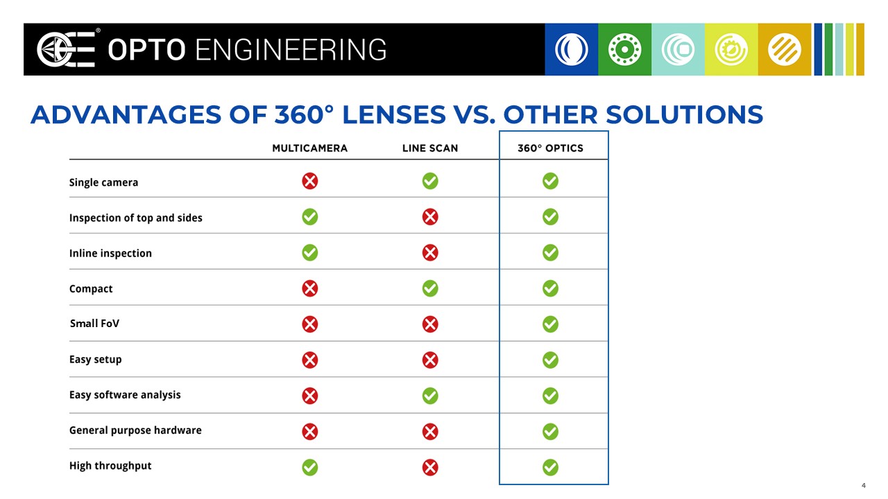
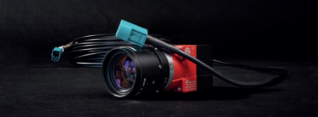
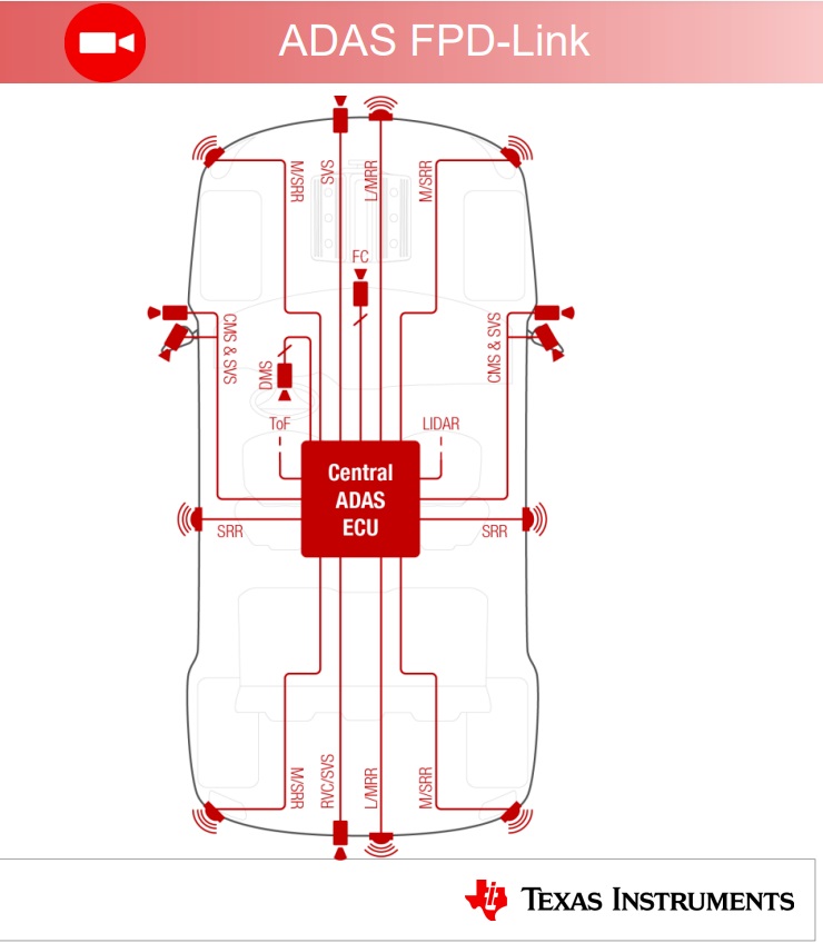

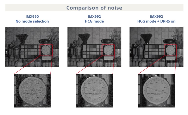
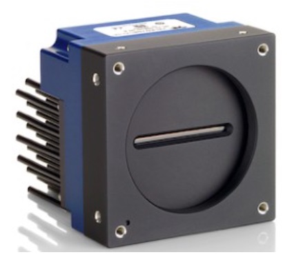
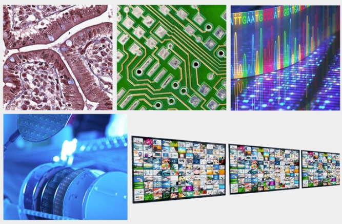
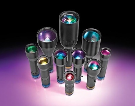
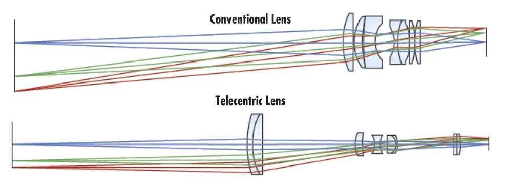
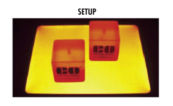
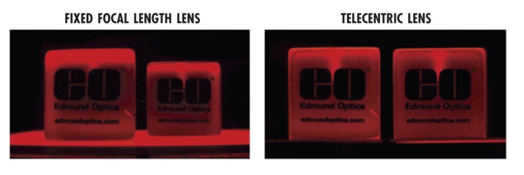
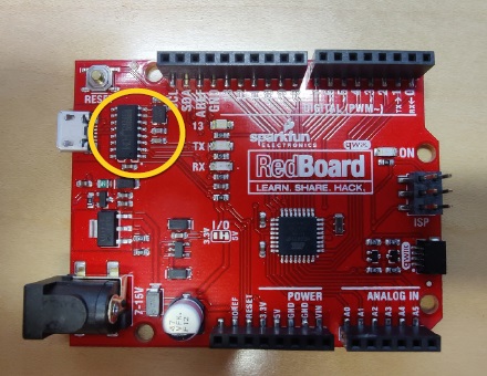
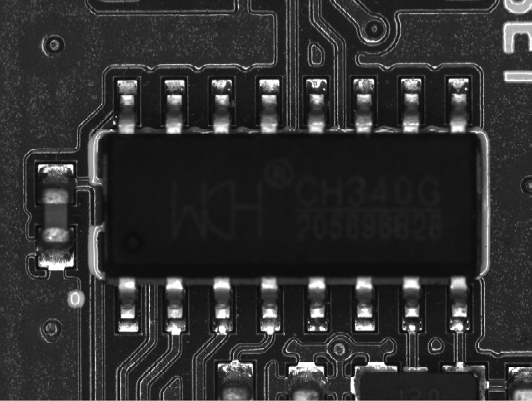
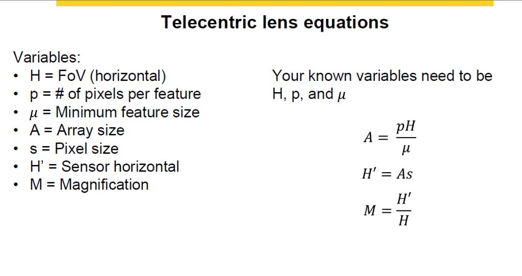
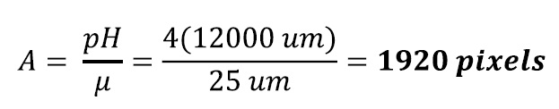
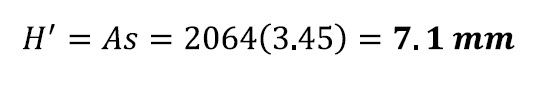
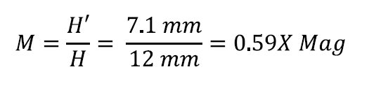
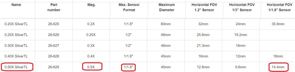
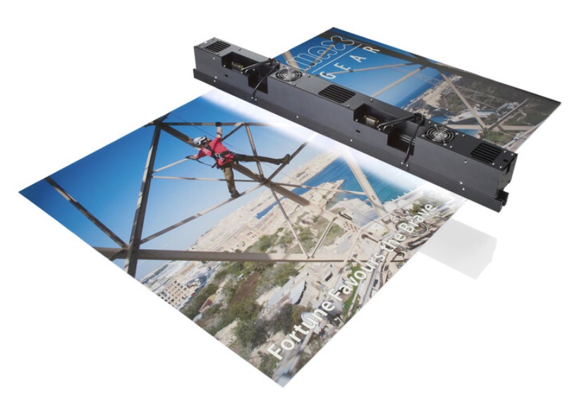

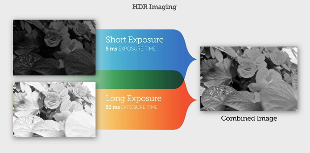
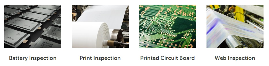
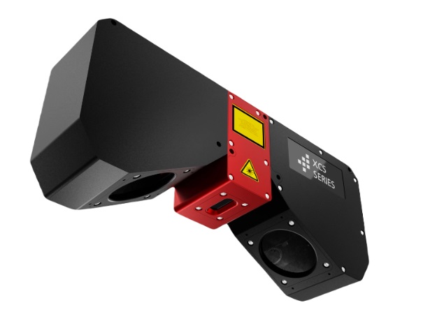
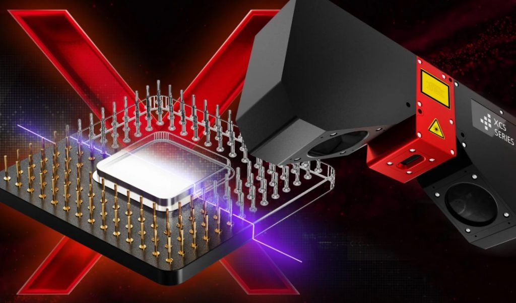
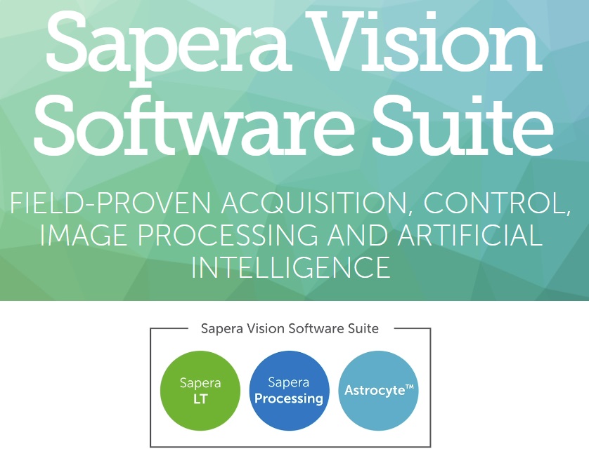
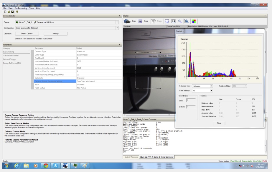
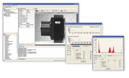
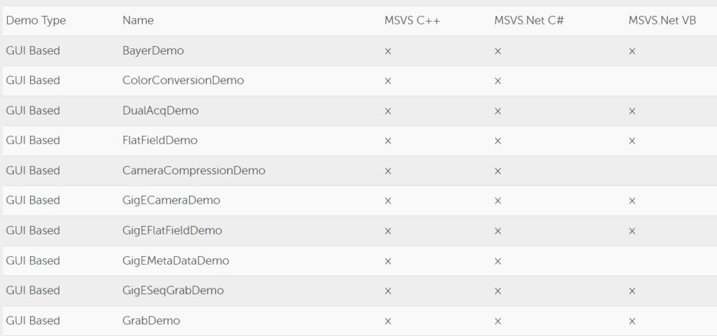
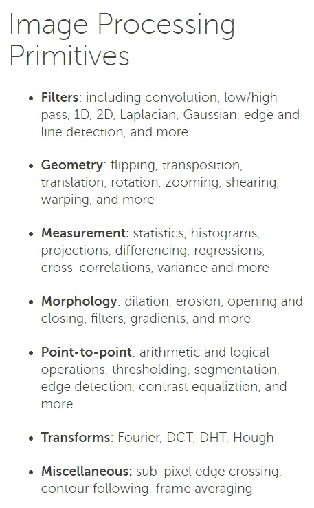
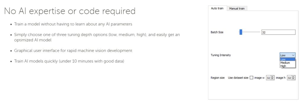
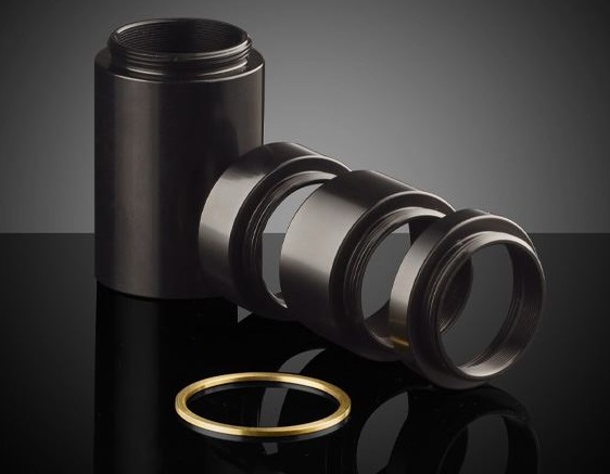
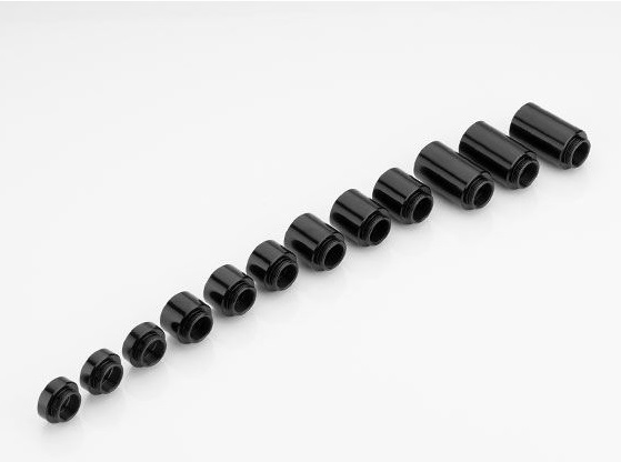
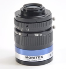
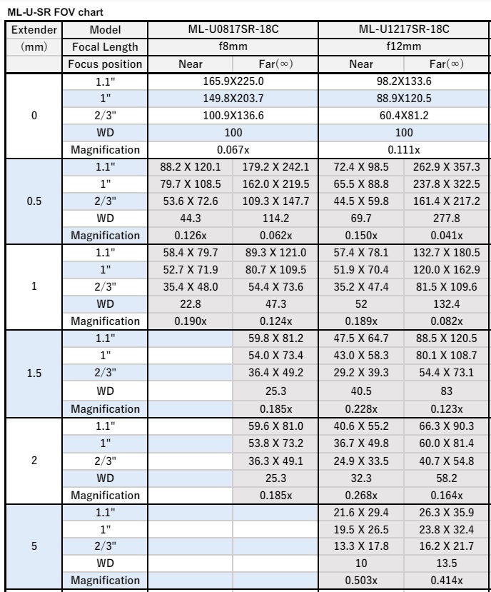

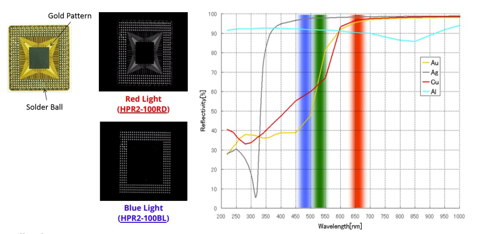
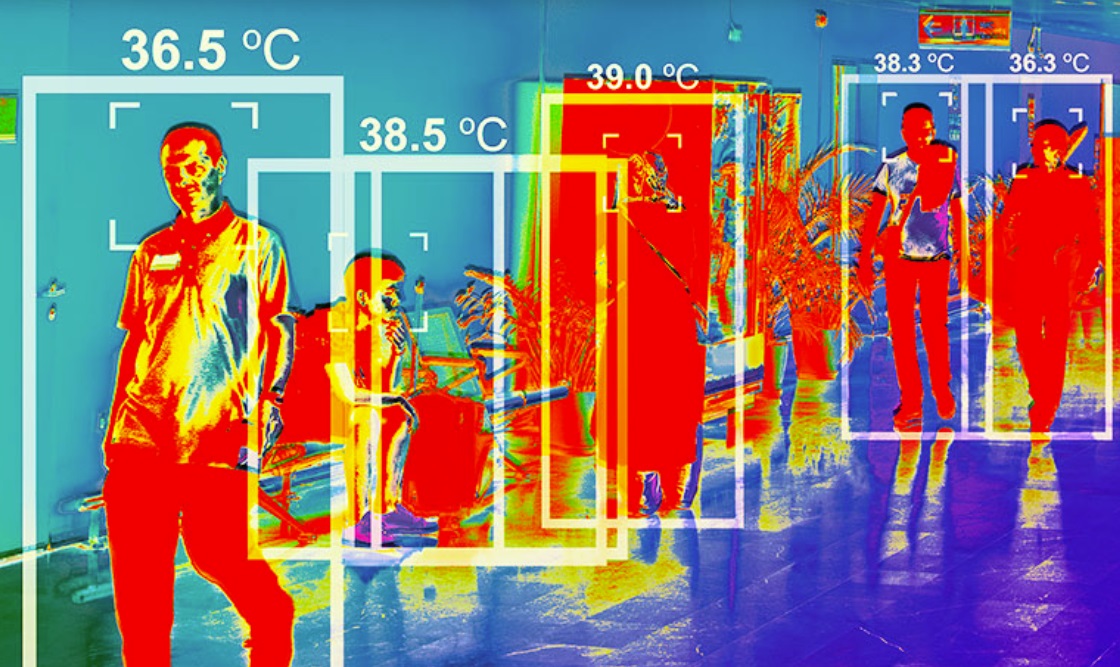
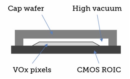
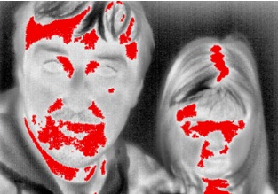
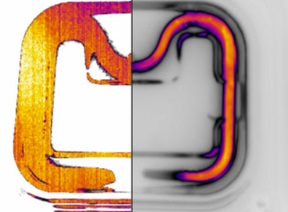
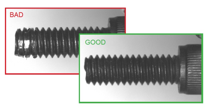
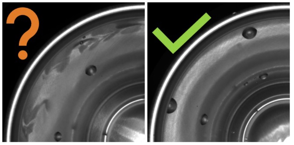
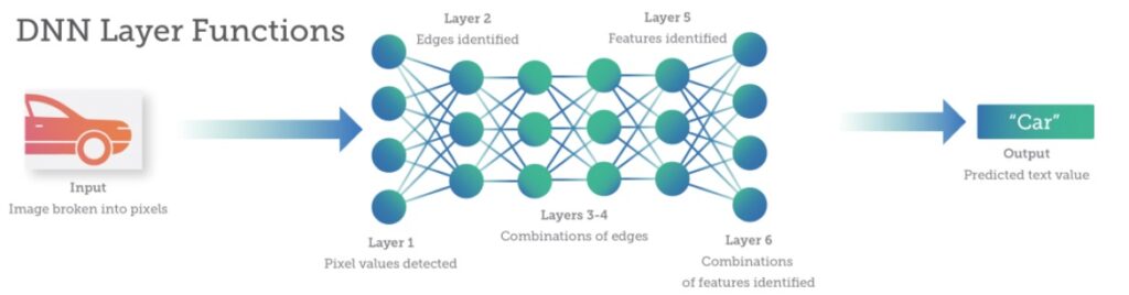
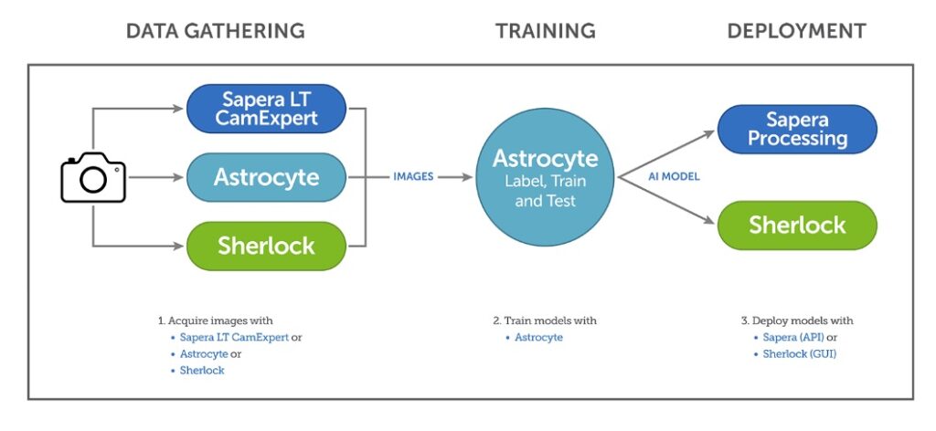
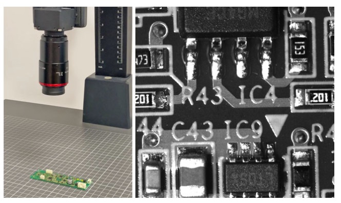
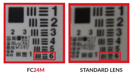
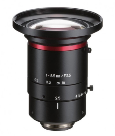
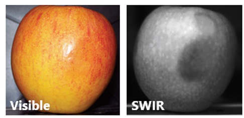
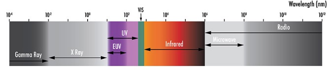
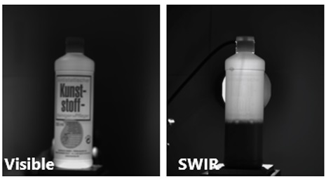
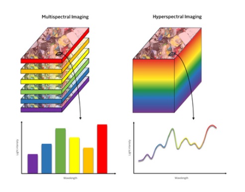
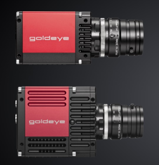
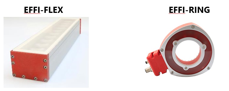
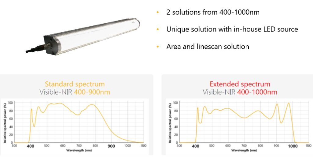
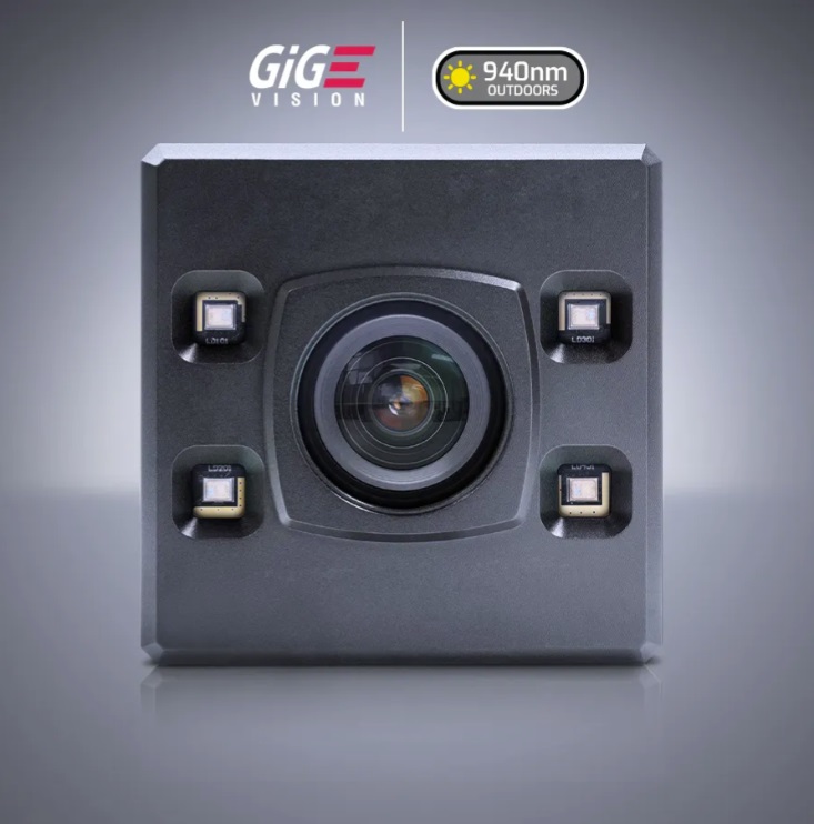

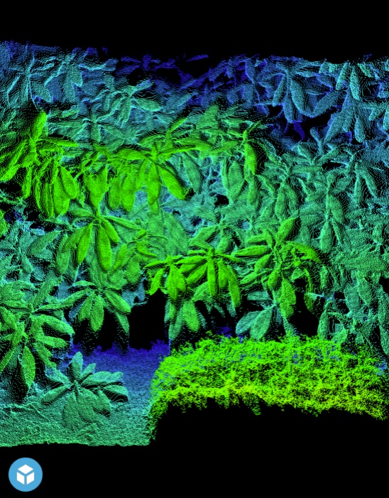
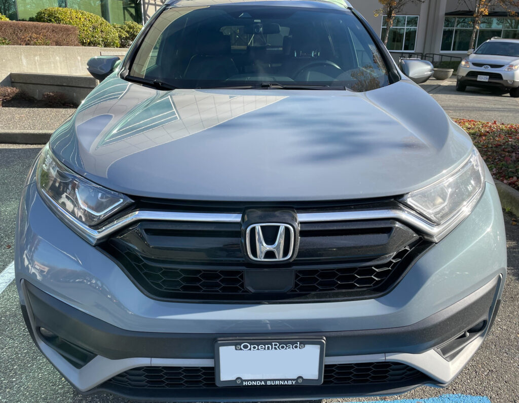
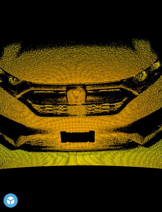
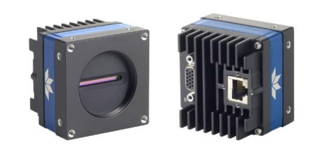
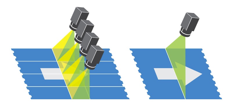
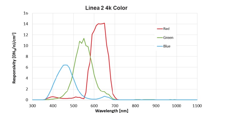
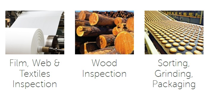
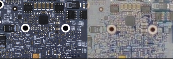
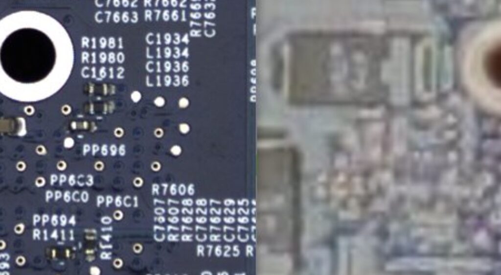

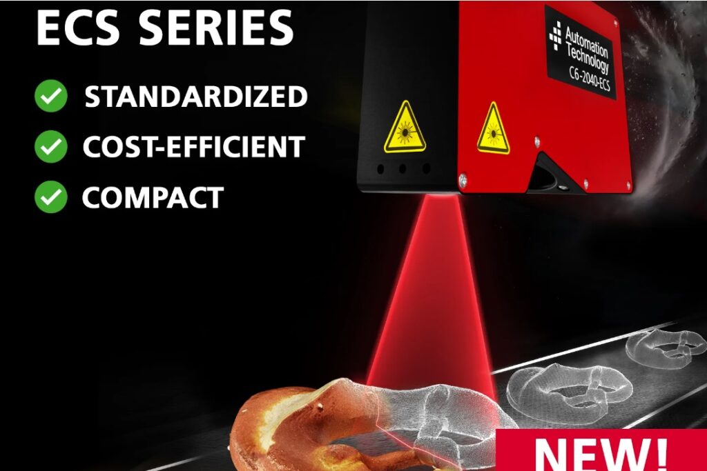
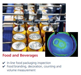
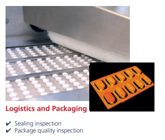
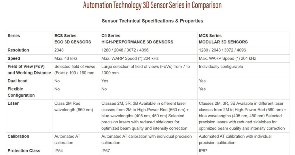
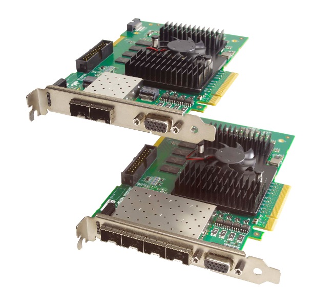
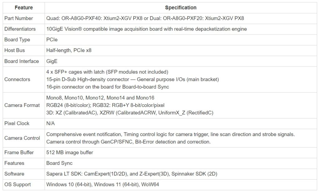
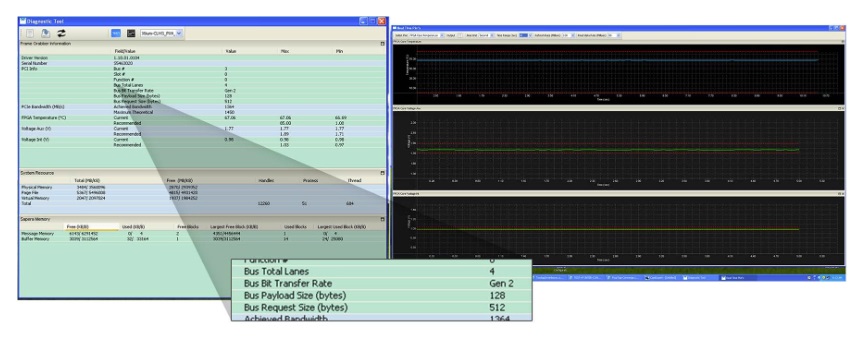
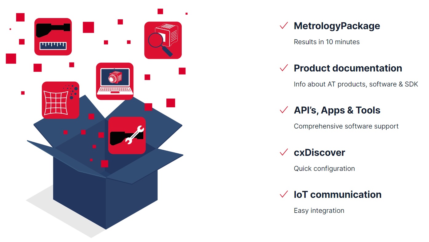

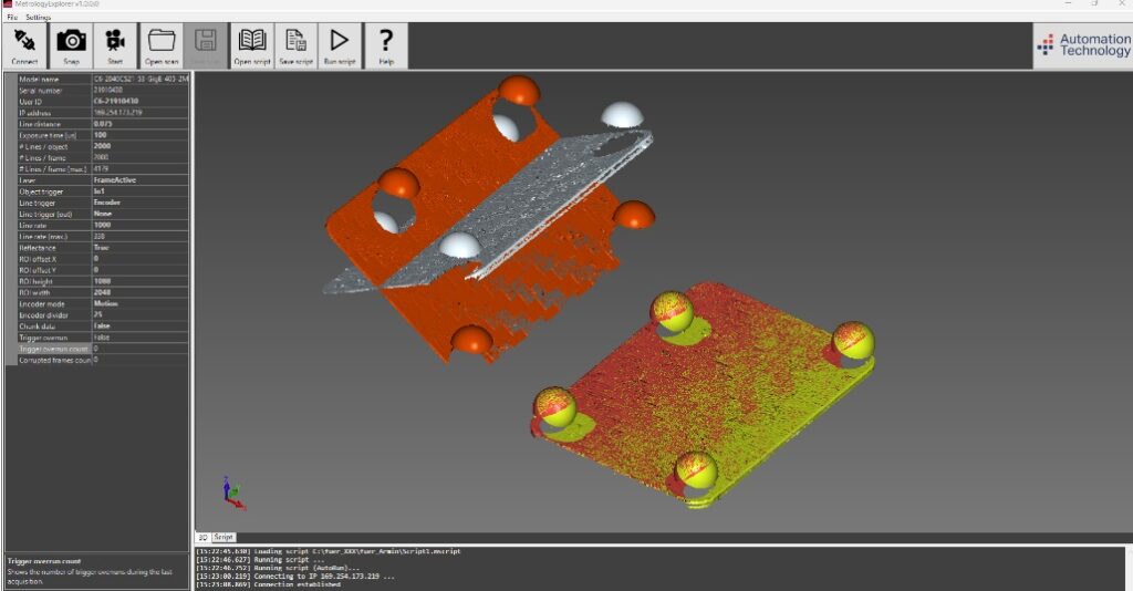
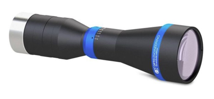
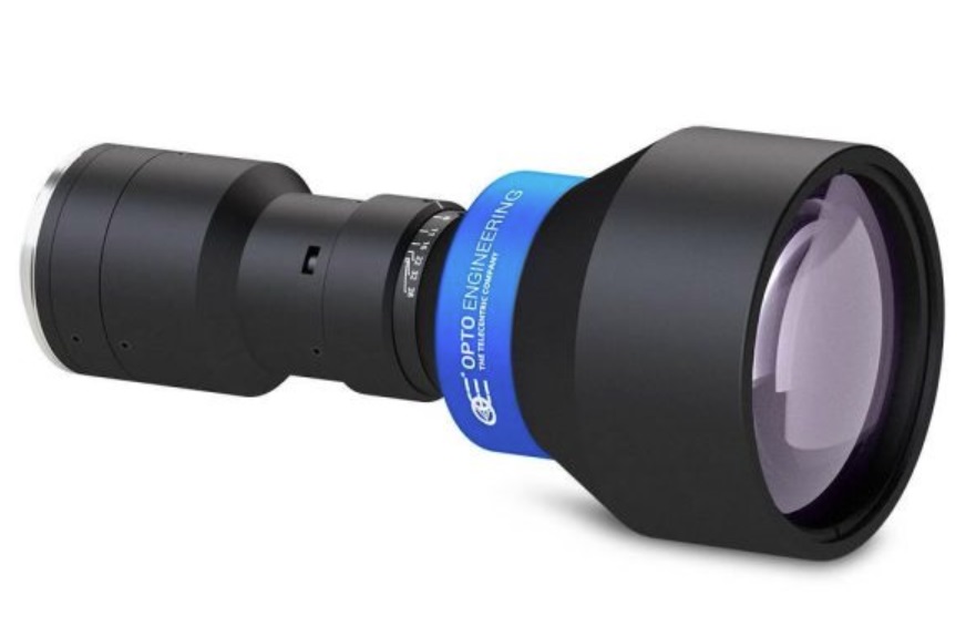
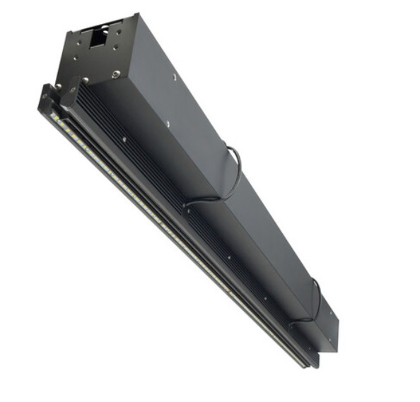
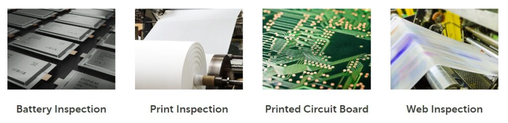
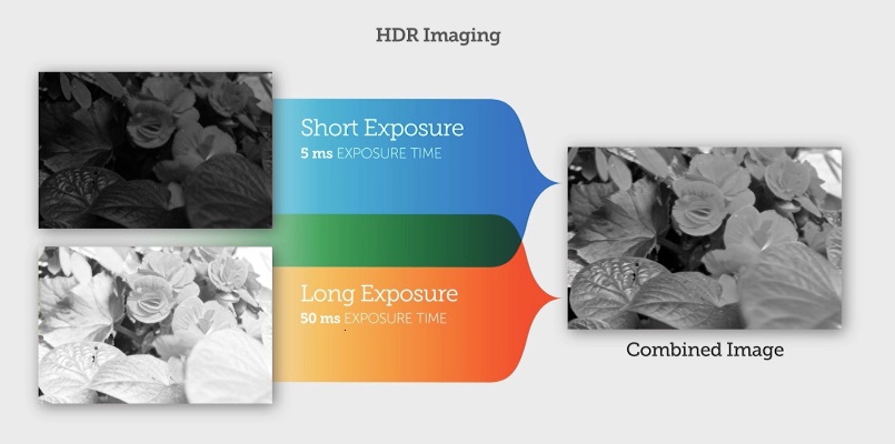
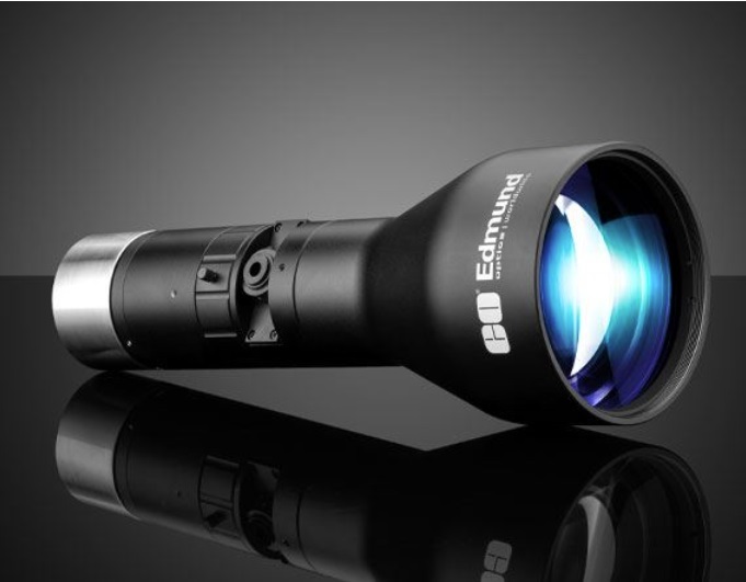
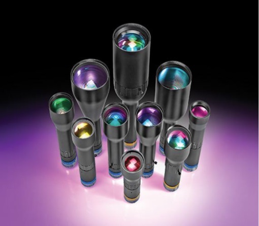
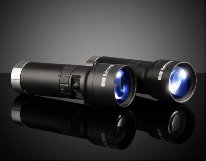
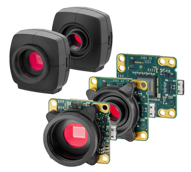
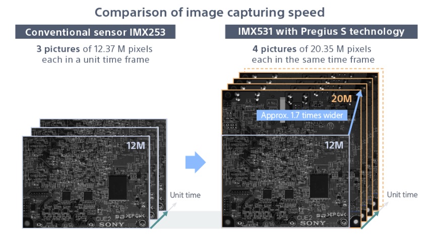
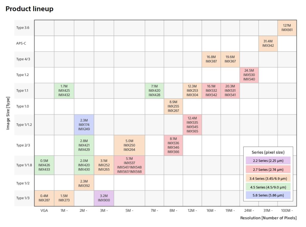
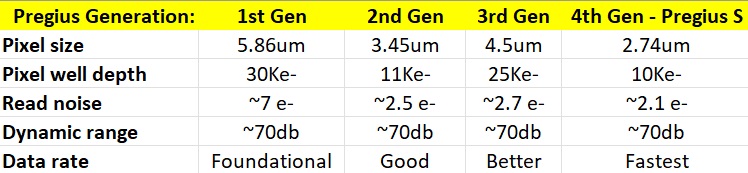
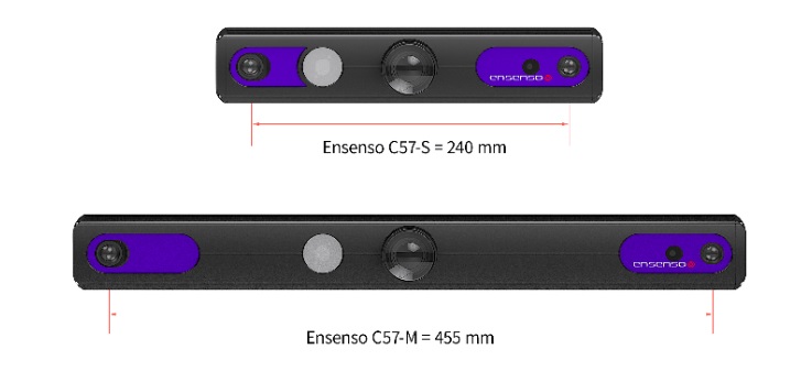


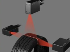
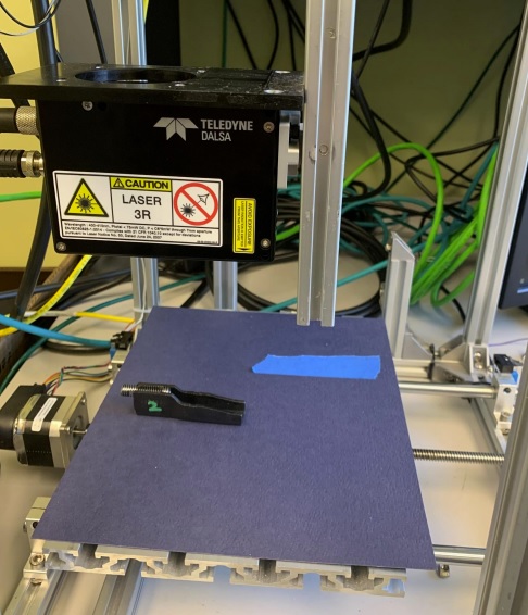
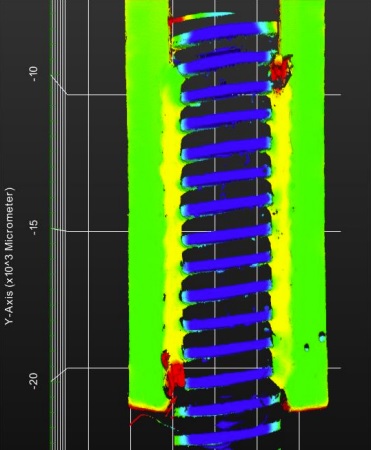
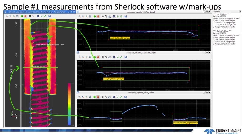
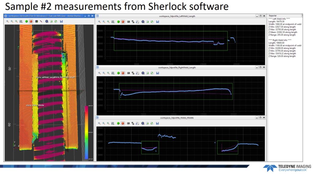
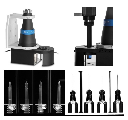
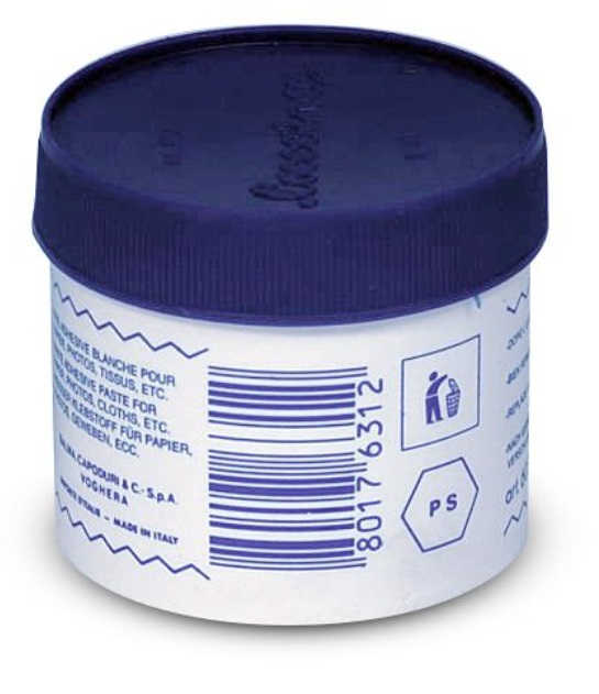
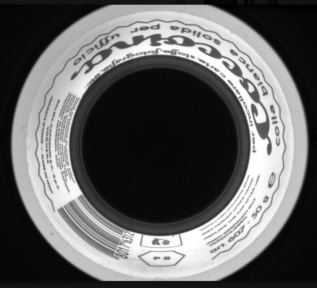
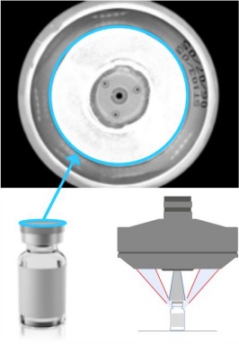
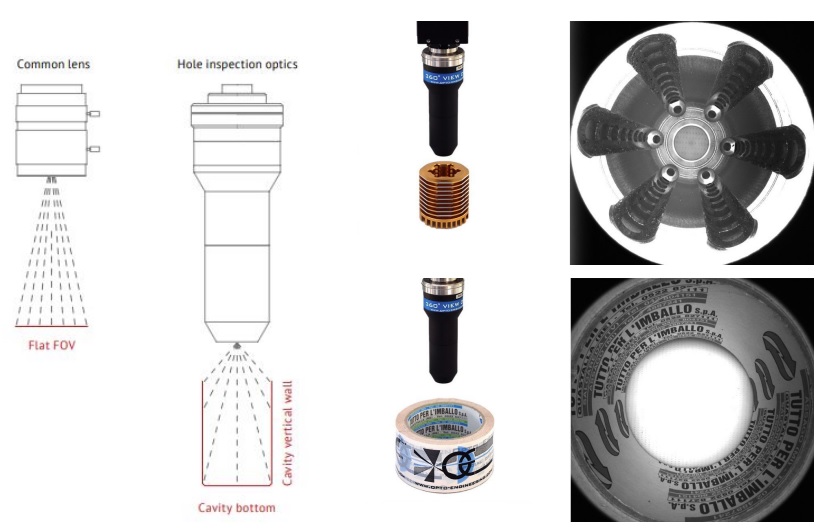
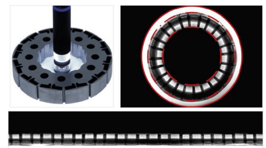
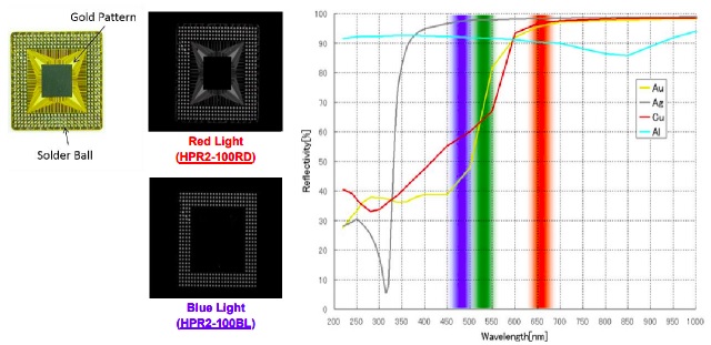

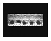
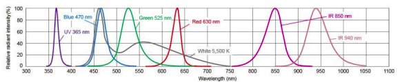
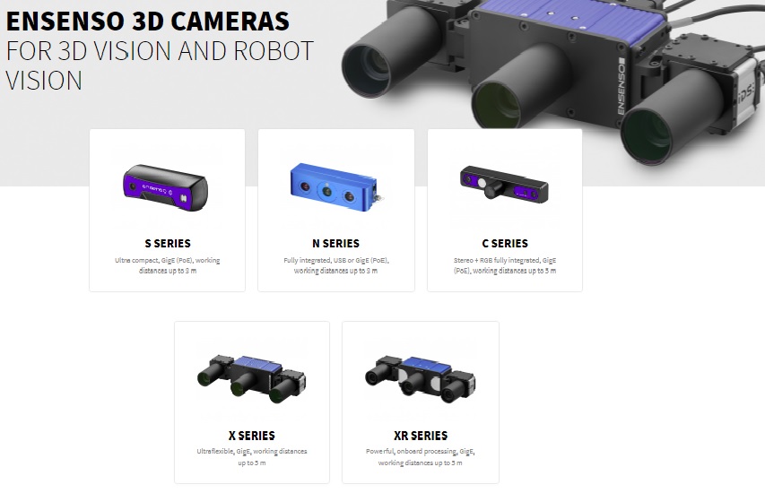
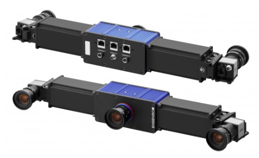
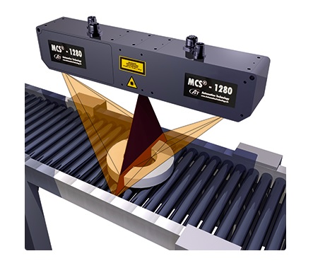
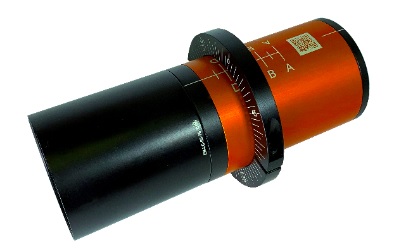
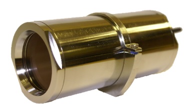
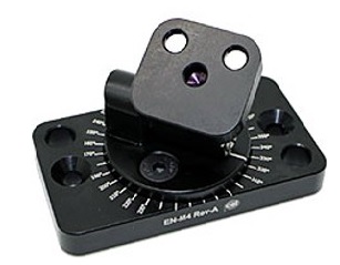
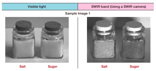


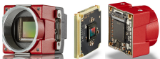
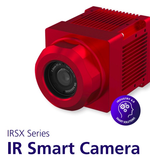

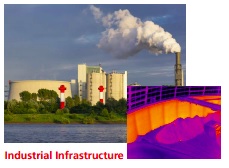
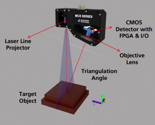
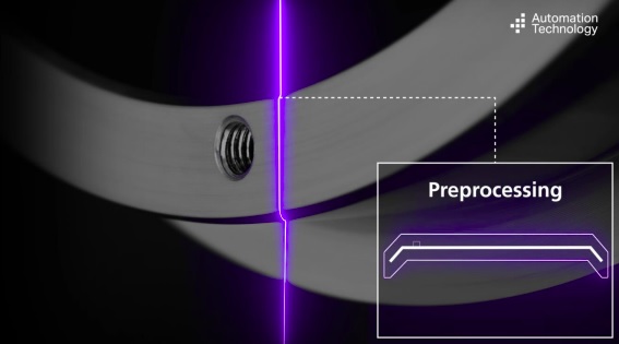
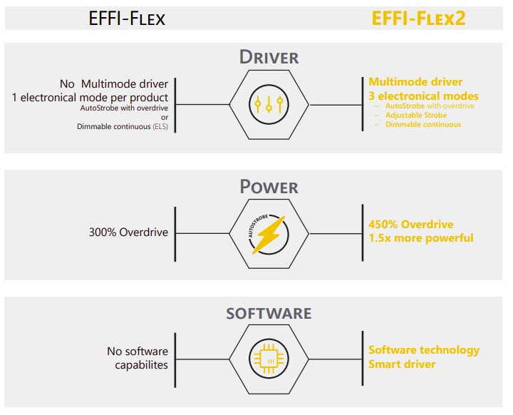
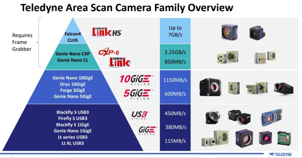
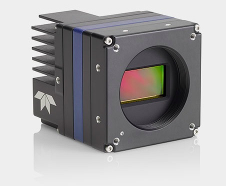
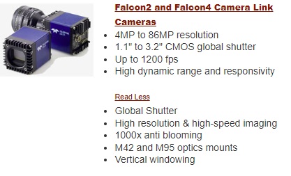
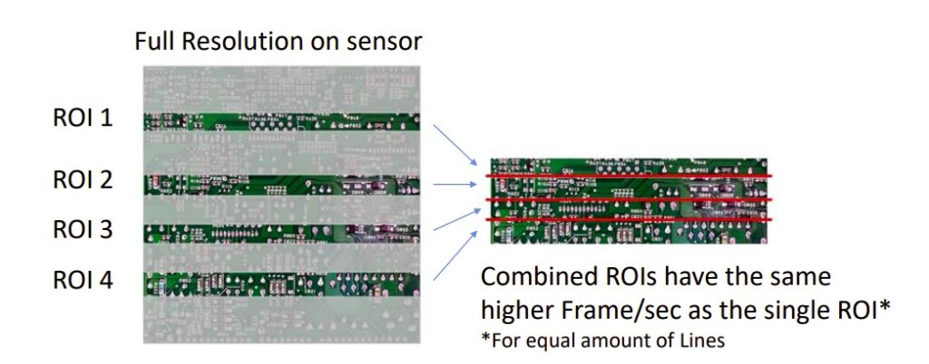
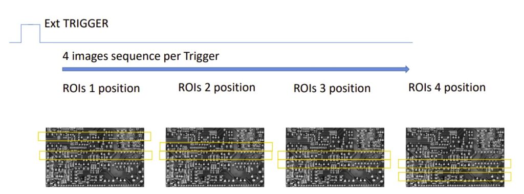
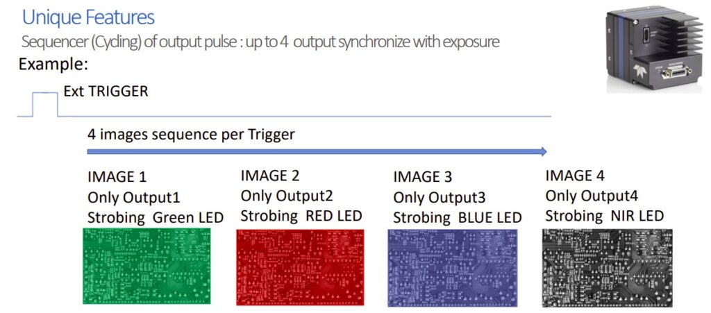
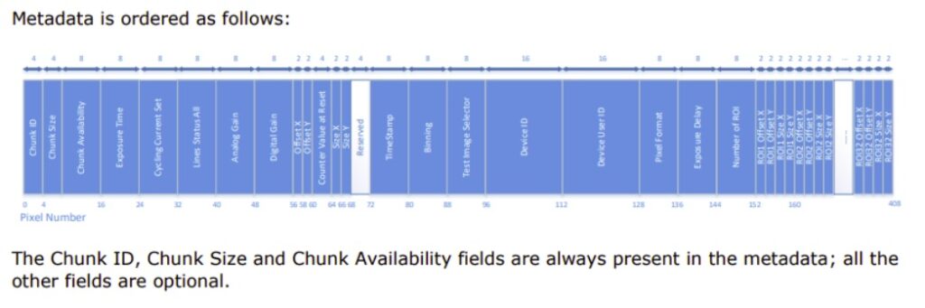
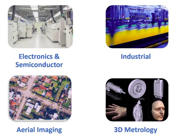
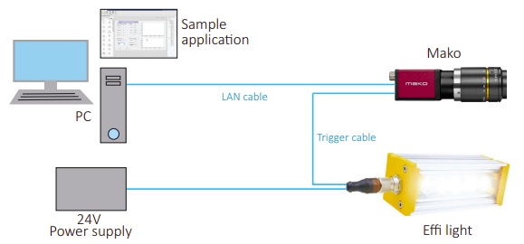
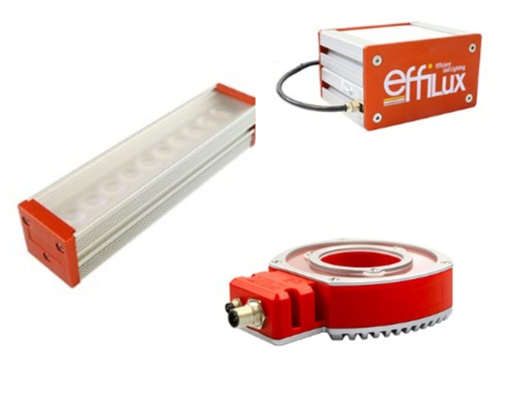
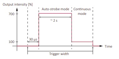

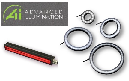
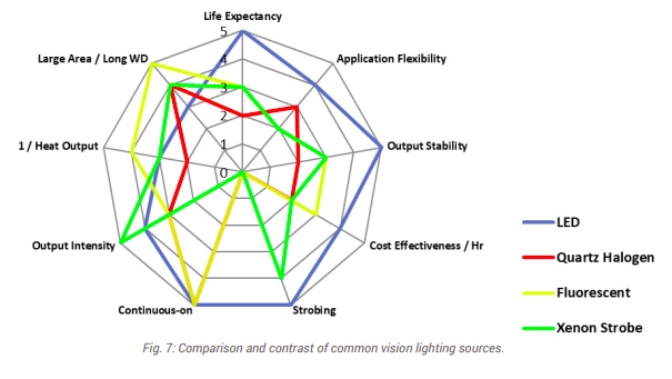
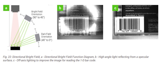
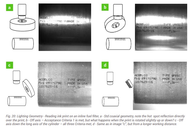
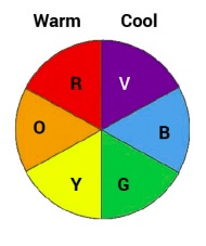
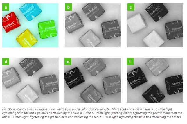
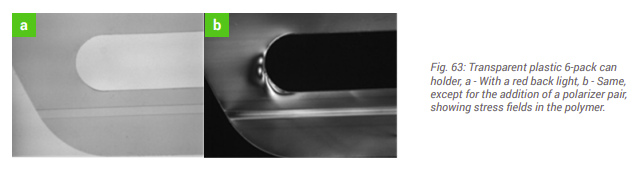
 When new technologies or product offerings are introduced, it can help get the creative juices flowing by seeing example applications. In this case, 3D laser triangulation isn’t new, and