Machine vision – indeed human vision too – relies heavily on contrast. The feature(s) being identified need to stand out against any competing candidate features. Otherwise confusion is present. Which means vision either doesn’t work, or isn’t efficient.
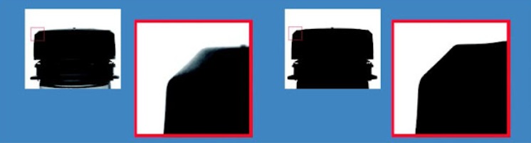
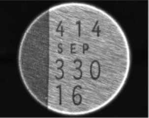
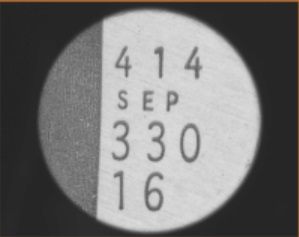
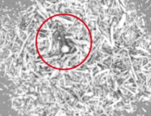
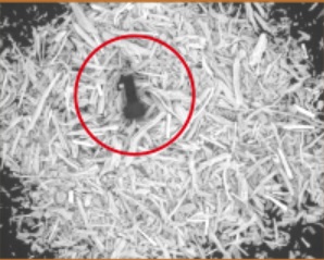
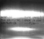
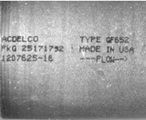
While it’s easy to achieve good contrast in certain machine vision applications, sometimes we’re presented with the special challenges of glare. The target object is the same, in the two images below. If the goal is to read the alphanumeric information, which image would you rather pass to your machine vision software?
Advanced Illumination
Techniques to eliminate glare
Glare can arise due to highly reflective surfaces, especially in combination with the direction of the light source relative to the lens and sensor capturing the image. Thankfully there are a number of techniques to eliminate or substantially reduce glare.
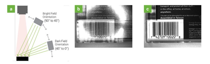
Off-axis lighting
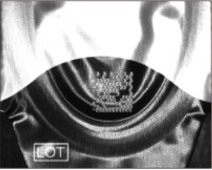
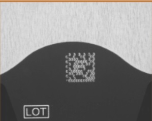
For the 1-D bar code reading application illustrated below, moving the light to an off-axis position creates dark field orientation, eliminating the glare. Identical materials but different geometry does the trick!
Diverse lights and geometries
Consider another example. In this case we have a titration tray, with multiple wells. Each well has a laser-etched 2-D code.
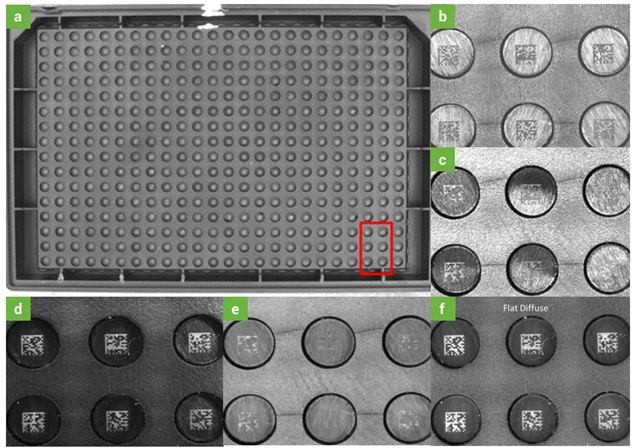
- (a) the titration tray at low resolution, marked up with red outline around 6 wells isolated in high resolution images (b) – (f)
- (b) High-angle ring light
- (c) Coaxial light
- (d) Dark field ring light
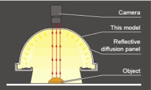
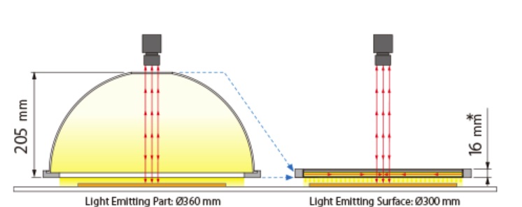
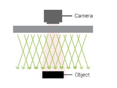
- (e) Diffuse dome light
- (f) Flat diffuse light
In this scenario, both (d) the dark field ring light, and (f) the flat diffuse light, are far superior to the other options, and the flat diffuse light is the winner.
NOTE: The example above is NOT meant to suggest that flat diffuse light is always the winner. It’s important to understand the characteristics of the surface you are inspecting, and each candidate type of lighting, and the geometric options. And to test!
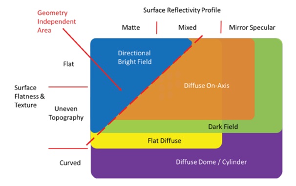
Guideline
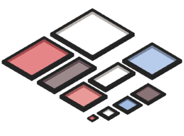
The following diagram is a general guideline, based upon the two most prevalent surface characteristics: (1) Surface flatness and texture, and (2) Surface reflectivity profile
Send your samples
Lighting is a complex topic, so we’re happy to help. If you are uncertain which light type to choose and how to configure, we may be able to do some testing for you. Contact us to arrange sending samples to test in our lab, and we can recommend sensor, lensing, lighting, and configuration options.
For comprehensive coverage on glare reduction – and more – download A Practical Guide to Machine Vision lighting from our knowledge base.

1st Vision’s sales engineers have over 100 years of combined experience to assist in your camera and components selection. With a large portfolio of cameras, lenses, cables, NIC cards and industrial computers, we can provide a full vision solution!
About you: We want to hear from you! We’ve built our brand on our know-how and like to educate the marketplace on imaging technology topics… What would you like to hear about?… Drop a line to info@1stvision.com with what topics you’d like to know more about.
#glare
#contrast
#machinevisionlighting
#diffuser
#polariser