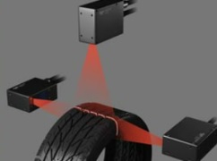
Have you wondered if 3D laser profiling would work for your application? Unless you have experience in 3D imaging, for which laser profiling is one of several popular methods, you may be uncertain of the fit for your application. Yes, one can read a comprehensive Tech Briefs on 3D methods, or product specifications, but wouldn’t it be helpful to see some images of your parts taken with an actual 3D Laser Profiler?

While prototyping at your facility is of course one option, if your target objects can be shipped, Teledyne DALSA has a Z-Trak Application Lab, whose services we may be able to arrange at no cost to you. Just describe your application requirements to us, and if 3D laser profiling sounds promising, the service works as follows:
- Send in representative samples (e.g. good part, bad part)
- We’ll configure Z-Trak Application Lab relative to sample size, shape, and applications goals, and run the samples to obtain images and data
- We’ll send you data, images, and reports
- Together we’ll interpret the results and you can decide if laser profiling is something you want to pursue
Really, just send samples in? Anything goes? Well not anything. It can’t be 50 meters long. Maybe a 15 centimeter subset would be good enough for proof of concept? And if the sample is a foodstuff, it can’t suffer overnight spoilage before it arrives.
A phone conversation that discusses the objects to be inspected, their dimensions, and the applications goal(s) is all we need to qualify accepting your samples for a test. Image courtesy of Teledyne DALSA.
Case study
In this segment, we feature outtakes from a recent use of the Z-Trak Application Lab, for a customer who needs to do weld seam inspections. The objective is to image a metal part with two weld seams using a Z-Trak 3D Laser Profiler and produce 3D images for evaluation of application feasibility. The images and texts shown here are taken from an actual report prepared for a prospective customer, to give you an understanding of the service.
Equipment:
- Z-Trak LP1-1040-B2
- Movable X,Y stage
X-Resolution: ~25 um
Y-Resolution: 40 um
WD: ~50 mm
Image courtesy Teledyne DALSA
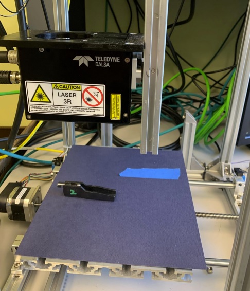
Conditions:
The metal part was laid flat on the X,Y stage under the Z-Trak. The stage was moved
to scan the part.
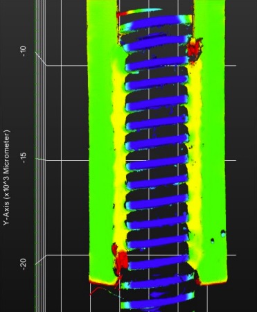
To the right, see the image generated from a perpendicular scan of the metal part. Image courtesy Teledyne DALSA.
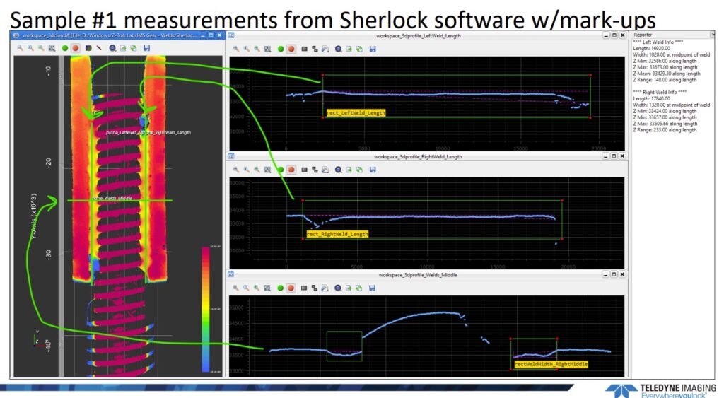
The composite image below requires some explanation. The graphs on the middle column, from top to bottom, show Left-Weld-Length, Right-Weld-Length, and Weld-Midpoint-Width (between the left and right welds), respectively. The green markup arrows help you correlate the measurements to the image on the left. The rightmost column includes summary measurements such as Min, Max, and Mean values.
Now have a look at a similar screenshot, for Sample #2, which includes a “bad weld”:
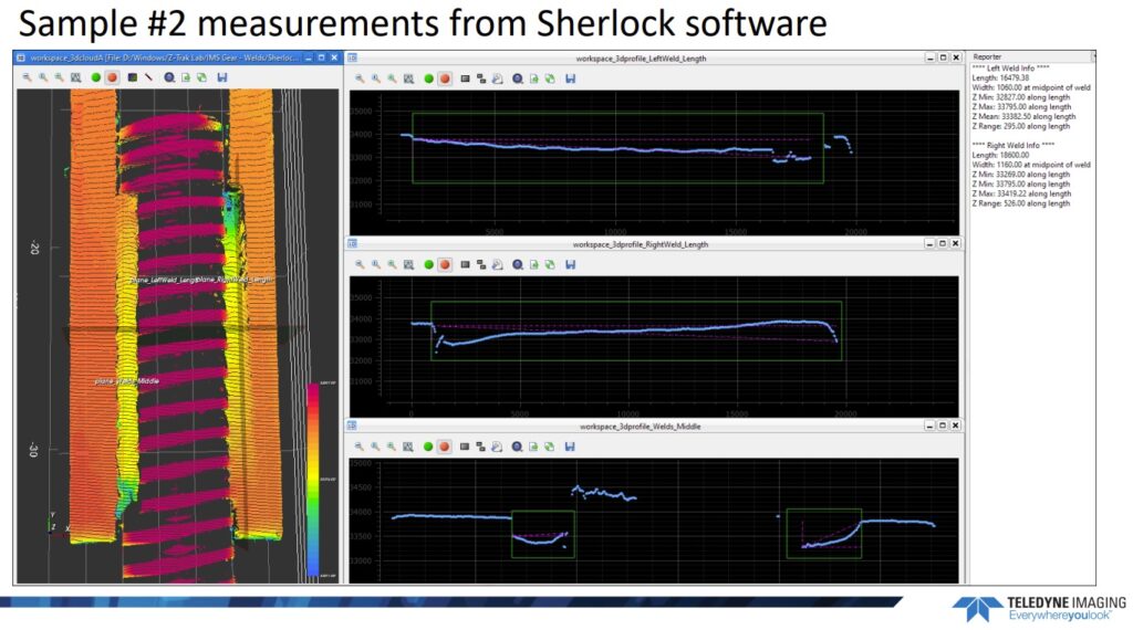
With reference to the image above, the customer report included the following passage:
The top-right image is the left weld seam profile. In the Reporter window the measurement of this seam is 1694.79 mm long. However, a defect can be noted at the bottom of the left weld. In addition to the defect it can be seen from the profile that the weld is not straight in the Z-direction. The weld is closer to the surface at the top and further from the surface at the bottom
Translation: The automated inspection reveals the defective weld! Naturally one would have to dig in further regarding definitions of “good weld”, “bad weld”, tolerances, where to set thresholds to balance yields and quality standards vs. too many false positives, etc.
Conclusion
The report provided to the customer concluded that “This application is feasible using a Z-Trak 3D Laser Profiler.” While it’s likely that outcome will be achieved if we qualify your samples and application to use the Z-Trak Application Lab service, it’s not a foregone conclusion. We at 1stVision and our partner Teledyne DALSA are in the business of helping customers succeed, so we’re not going to raise false hopes of application success.
Recap
To summarize, the segments above are representative outtakes from an actual report prepared by the Z-Trak Application Lab. The full report contains more images, data, and analysis. Our goal here is to give you a taste for the complimentary service, to help you consider whether it might be helpful for your own application planning process.
Next steps?
To learn more, see a recent blog “Which Z-Trak 3D camera is best for my application?“. Or have a look at the Z-Trak product overview.
If you’d like to send in your parts, please use this “Contact Us” link or the one below. In the ‘Tell us about your project’ field, just write something like “I’d like to have parts sent to the Z-trak lab.” If you want to write additional details, that’s cool – but not required. We’ll call to discuss details at your convenience.

1st Vision’s sales engineers have over 100 years of combined experience to assist in your camera and components selection. With a large portfolio of lenses, cables, NIC card and industrial computers, we can provide a full vision solution!