IDS NION 3D Time of Flight camera | 1.2 MP Industrial ToF for Robotics and Automation

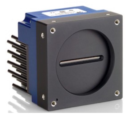
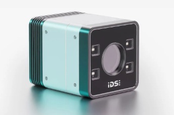
Next level time-of-flight – ToF. Nion combines spatial resolution of 1.2 MP (@30 fps) with reliable depth precision. Housed in a robust IP67 enclosure, Nion captures 3D for even fine structures – cost-efficiently.

Nion 3D ToF camera – Courtesy IDS Imaging

OnSemi AF0130 Hyperlux ID sensor

The AF0130 belongs to the Hyperlux ID family. It’s an Indirect Time of Flight (iToF) sensor, back side illuminated (BSI) CMOS global shutter depth and imaging solution. It calculates depth, confidence and intensity maps at high speeds from its laser modulated exposures.

Why is IDS Imaging introducing a ToF product

We’ve covered IDS evolving range of stereo vision 3D cameras previously, as recently as a few months ago, in Ensenso 3D for logistics applications.

But while powerful, stereo vision requires at least two cameras, and the corresponding electronics and software to synchronize the images and build the 3D model. So it can be overkill if you don’t need that level of performance.

With the Nion ToF product, IDS brings a more affordable 3D imaging solution to the market, which is more than good enough for many 3D applications .

The video below provides a nice overview. We tease out some of the key points in text and graphics further below, but you might like the dynamics of the video:

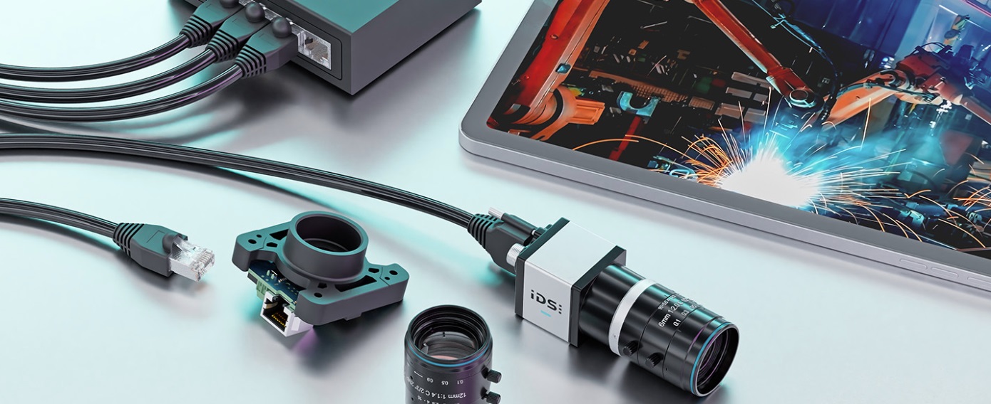
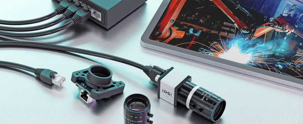
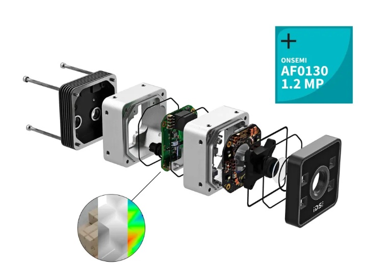
What’s inside that IP67 enclosure?

IP67 means dustproof and immersible in water to a depth of 1 meter for up to 30 minutes. That’s pretty robust. More than good enough for even the most challenging industrial environment, outdoor or wash down context.

Besides the tight enclosure, of course there’s a lens to focus the light source onto the sensor, electronics to support the GigE Vision interface, the sensor is the heart of the matter.

Exploded view of Nion camera – Courtesy IDS Imaging

Highest resolution industrial ToF camera

As this blog is released in April 2026, this is the highest resolution industrial ToF camera on the market.

In-sensor readout/storage reduces motion artefacts

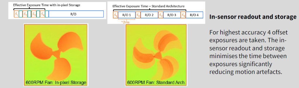
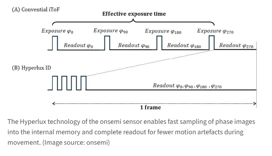
To calculate a single depth value, four coordinated exposures with different phase positions (typically 0°, 90°, 180° and 270°) are usually necessary. These four signals are then used to calculate the phase shift – and thus the distance. Thanks to its special pixel architecture and integrated on-chip processing, the AF0130 iToF sensor captures all four phase images in quick succession and stores them directly and completely in the chip’s memory – without any intermediate readout.

This significantly shortens the time between exposures and noticeably reduces motion blur. Another advantage of continuous reading: The depth information can be efficiently re-sorted and directly processed further – without time-consuming post-processing. This not only makes the camera more robust against movement, but also enables higher frame rates and reduces the load on the host system. This is a decisive advantage, particularly in dynamic applications such as robotics, logistics or pick-and-place.

Hyperlux technology by onsemi reduces motion artefacts
Courttesy IDS Imaging

Key takeaways on motion artefact reduction are:

Boiling the above section down to key takeaways, we note:

  1. Multi-phase demodulation (four, to be specific)
  2. Reduced motion artefacts in dynamic scences
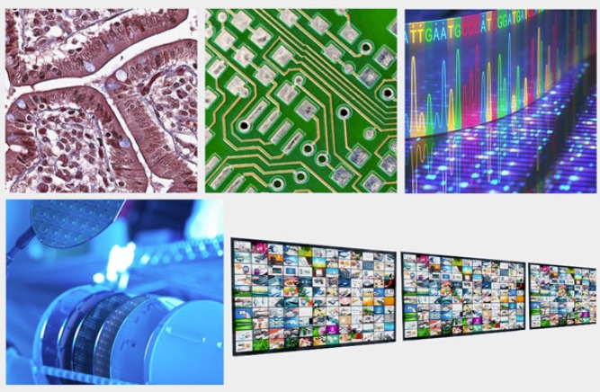
Suggested Markets

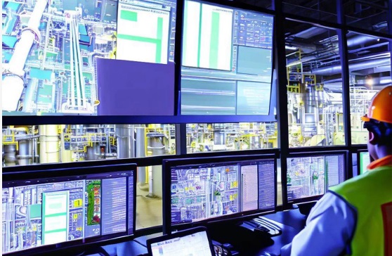
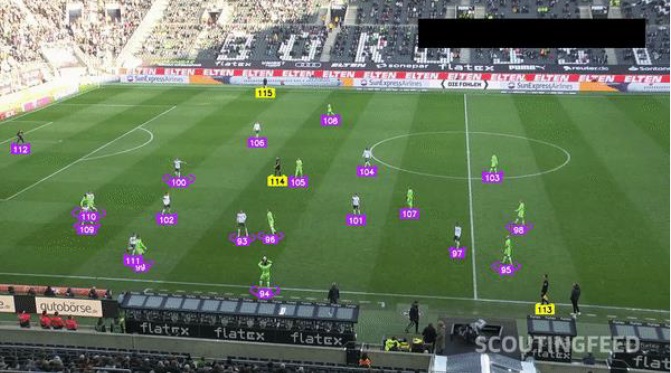
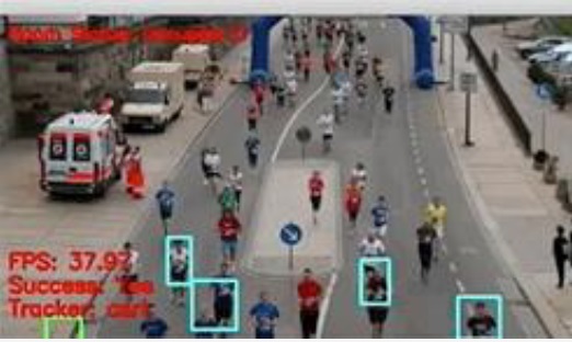
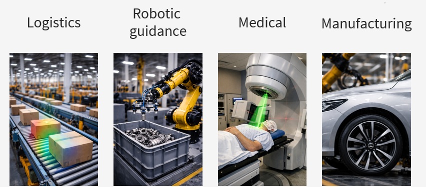
Just to whet the appetite, we call out logistics, robotics, medical, and manufacturing as sectors where affordable ToF 3D imaging can deliver value on investment. But of course you may have 3D applications in mind in another sector.

Courtesy IDS Imaging

1st Vision’s sales engineers have over 100 years of combined experience to assist in your camera and components selection.  With a large portfolio of cameraslensescablesNIC cards and industrial computers, we can provide a full vision solution!

About you: We want to hear from you!  We’ve built our brand on our know-how and like to educate the marketplace on imaging technology topics…  What would you like to hear about?… Drop a line to info@1stvision.com with what topics you’d like to know more about.

#3D

#Nion

#ToF

#timeofflight

#IDSImaging

Plug’n Stream IDS Imaging μEye SCP / μEye SLE industrial dashcams

Unpacking the μEye SCP/ μEyeSLE product names to preview what’s on offer, the “S” stands for Streaming. The rest of the product names come from IDS Imaging’s popular GigE Vision camera families μEye CP and μEye LE, respectively. So the value proposition is a bundled streaming solution piggybacked on top of another product platform. This creates economies of scale for the manufacturer and the customer alike.

uEye SCP / SLE single-device solution for process monitoring – Courtesy IDS Imaging

Continuous monitoring with event-triggered video recording

Anybody running complex systems has to monitor them for performance and quality control – and/or to recover from breakdowns or detected concerns. Traditionally one had two options:

  • Wait for a breakdown and try to deduce what went wrong, or
  • Construct a video monitoring system from the constituent components… and program as needed

The “wait and see” options is attractively inexpensive on the face of it. But it risks expensive losses from the period prior to detecting the failures. Worse, it may not be possible to determine what went wrong if one missed the event that triggered the failure.

Constructing a video monitoring system from scratch is possible – and many have done it. Until now it generally required sourcing camera, lens, and PC, and writing complex software capable of episodic streaming and recording, and event-detection and logging.

IDS μEye SCP / μEye SLE provide Plug’n Stream no-PC-needed solution

Systems evolution in many fields, including machine vision, periodically takes what once had to be programmed to something that need only be configured. The system provider helpfully packages the algorithms into parameterized controls that are user-friendly to the deployer. That way one can focus on the application domain, event management, and process control.

IDS Imaging has done exactly that to create μEye SCP / μEye SLE – think “industrial dashcam” – with both housed and board-level options. The comprehensive 9 minute video below provides a great introduction to the product, its capabilities, and some applications examples.

The comprehensive 9 minute video below provides a great introduction to the product, its capabilities, and some applications examples.


9 minute introduction and overview – Courtesy IDS Imaging

Event Recording

The system streams continuously to internal persistent memory, periodically overwriting previous streams that were not part of any events deemed worth saving. This creates a recorded stream for a defined period from x seconds prior to an event, through the event, and to y seconds afterwards, where x and y are user-definable.

That documents machine malfunctions or failures. Which makes it easier to analyze process errors – and address them for system improvement.

No PC needed – System on a Chip (SoC)

With System on a Chip (SoC) from Ambarella, the camera has the onboard smarts to directly process and evaluate image data.

The user need only configure the parameters that define an “event”, the duration to capture before and after the event, which of several formats to record, and whether to operate standalone or integrated into other systems.

Use cases

Just to get the juices flowing, consider use cases like the following:

Industrial process monitoring – the human operator has the overview but μEye SCP / SLE can monitor automatically at the detail level – recording events and raising alerts if needed – Courtesy IDS Imaging
Video analysis – for scouting or officiating for example – Courtesy IDS Imaging
Smart city applications – let the system identify pedestrians within a specific field of view – Courtesy IDS Imaging

WebCockpit configuration

With no PC required to operate the system in standalone mode, configuration may be done through a frontend in the browser. The frontend settings control streaming, recording, and video modes.

Optionally on can use the web service and a REST API to seamlessly integrate into existing systems, for those who prefer or require integrate over standalone deployments.

1st Vision’s sales engineers have over 100 years of combined experience to assist in your camera and components selection.  With a large portfolio of cameraslensescablesNIC cards and industrial computers, we can provide a full vision solution!

About you: We want to hear from you!  We’ve built our brand on our know-how and like to educate the marketplace on imaging technology topics…  What would you like to hear about?… Drop a line to info@1stvision.com with what topics you’d like to know more about.

Teledyne DALSA Linea 9K Line scan NUV+VIS

Some applications require line scan cameras, where the continuously moving “product” is passed below a sensor that is wide in one dimension and narrow in the other, and fast enough to keep up with the pace of motion. See our piece on area scan vs. line scan cameras for an overview.

Teledyne DALSA’s new Linea HS 9k BSI Near ultraviolet (NUV) / visible camera is such a line scan camera, at 9216 x 192 resolution, and speeds to 400 kHz (mono mode) and 200 kHz (HDR mode).

Linea HS 9k BSI (NUV) / visible camera – Courtesy Teledyne DALSA

Visible spectrum as well as Near Ultraviolet (NUV)

The camera uses Teledyne DALSA’s own charge-domain CMOS TDI sensor with a 5×5 μm pixel size. In addition to the visible spectrum 400 nm – 700 nm, the sensor delivers good quantum efficiency to 300 nm, qualifying Near Ultraviolet (NUV) applications in the blue range as well.

Backside illumination enhances performance

Backside illumination (BSI) improves quantum efficiency (QE) in both the UV and visible wavelengths, boosting the signal-to-noise ratio.

Interface

The Linea HS 9k BSI camera uses the CLHS (Camera Link High Speed) data interface to provide a single-cable solution for data, power, and strobe. And Active optical cable (AOC) connectors support distances up to 100m. That avoids the need for a repeater while achieving data reliability and cost control. See an overview of the Camera Link standards. Or see all of 1stVision’s Camera Link HS cameras.

Applications

Delivering high speed high sensitivity images in low light conditions, the Linea 9k HS is used in applications such as:

  • PCB inspection
  • Wafer inspection
  • Digital pathology
  • Gene sequencing
  • FPD inspection
Linea 9k HS suitable for diverse applications – Courtesy Teledyne DALSA

Request a quote

The part number for the Linea HS 9k BSI camera is DALSA HL-HM-09K40H.

Lots of line scan cameras to choose from

Teledyne DALSA’s Linea families have a variety of interfaces, resolutions, frame rates, pixel sizes, and options. So if the new model isn’t the right one for your needs, browse the link at the start of this sentence, or ask us to guide you among the many choices.

1st Vision’s sales engineers have over 100 years of combined experience to assist in your camera and components selection.  With a large portfolio of cameraslensescablesNIC cards and industrial computers, we can provide a full vision solution!

About you: We want to hear from you!  We’ve built our brand on our know-how and like to educate the marketplace on imaging technology topics…  What would you like to hear about?… Drop a line to info@1stvision.com with what topics you’d like to know more about

AT Sensors – XCS 3D Sensor Laser Profiler

Ideal for industrial applications requiring precision, reliability, high speed, and high resolution, AT Sensors (previously known as Automation Technology) XCS 3D sensor laser profiler 3070 WARP achieves speeds up to 200 kHZ with the dual head model. Even the single head can achieve 140 kHz. The key innovations in the XCS series are in the laser-line projection technology.

XCS 3D sensor laser profiler – Courtesy AT Sensors

Aren’t all 3D sensor laser profilers similar?

Many indeed share underlying similarities. Often they use triangulation to make their measurement. And the output is a 3D profile (or point cloud) of a target, built up by rapid laser pulsed stepwise “slices” of the X dimension as the target (or sensor) moves in the Y dimension. Triangulation determines variances in the Z dimension based on how the laser angle reflects from the target surface coordinate onto the sensor. For a brief refresher on the concepts, see our overview article and illustrations.

What’s special about AT Sensors XCS Series?

Key attributes are shown in the video and called out in the following text.

30 second overview of XCS series

Homogeneous thickness laser line

Using special optics, the XCS series projects a laser line of homogeneous thickness across the target surface. AT Sensors uses Field Curvature Correction (FCC) to create the uniform projection, overcoming the so-called line “bow” effect. This enables precise scanning of even small structures – regardless of whether such features are in the middle or edge of the laser line. What’s the benefit for the customer? It enables applications with high repeatability and accuracy – such as for ball grid arrays (BGAs), pin grid arrays (PGAs), and surface mount devices (SMDs).

Clean Beam Technology

The XCS Series utilizes AT Sensors own Clean Beam function to insure a precisely focused laser beam, effectively suppressing side lobe noise interference.. Clean Beam also assures a uniform intensity distribution, which also contributes to the reliably consistent results.

Scanning a pin-grid array (PGA) – Courtesy AT Sensors

Optional Dual Head to avoid occlusion

X FOV 53mm +/-

X Resolution 13mm +/-

Z Range to 20mm

Z Resolution to 0.4 µm

GigE Vision interface, GenICam compliant

For plug and play configuration with networking cables and adapter cards familiar to many, the GigE Vision interface is one of the most popular machine vision standards. And GenICam compliance means you can use AT – Automation Technology’s software or diverse 3rd party SDKs.

Additional features

Automatic RegionTracking, Automatic RegionSearch, Multiple Regions, MultiPart, AutoStart, History Buffer, Multi-Slope, MultiPeak

contact us

Is the XCS 3D sensor laser profiler best for your application?

AT Sensors is confident there are demanding users for whom the XCS 3D laser profiler delivers just the right value proposition. Is that what your application requires? But AT also provides 3 other product families of laser profilers, including the CS Series, the MCS Series, and the ECS Series. It all comes down to speed and resolution requirements, field of view (FOV), and cost.

1st Vision’s sales engineers have over 100 years of combined experience to assist in your camera and components selection.  With a large portfolio of cameraslensescablesNIC cards and industrial computers, we can provide a full vision solution!

About you: We want to hear from you!  We’ve built our brand on our know-how and like to educate the marketplace on imaging technology topics…  What would you like to hear about?… Drop a line to info@1stvision.com with what topics you’d like to know more about.