Most who are involved with imaging have at least some understanding of depth of field (DoF). DoF is the distance between the nearest and furthest points that are acceptably in focus. In portrait photography, one sometimes seeks a narrow depth of field to draw attention to the subject, while intentionally blurring the background to a “soft focus”. But in machine vision, it’s often preferred to maximize depth of field – that way if successive targets vary in their Z dimension – or if the camera is on a moving vehicle – the imaging system can keep processing without errors or waste.
Making it real
Suppose you need to see small features on an item that has various heights (Z dimension). You may estimate you need a 1″ depth of field. You know you’ve got plenty of light. So you set the lens to f11 because the datasheet shows you’ll reach the depth of field desired. But you can’t resolve the details! What’s up?
So I should maximize DoF, right?
Well generally speaking, yes – to a point. The point where diffraction limits negatively impact resolution. If you read on, we aim to provide a practical overview of some important concepts and a rule of thumb to guide you through this complex topic without much math.
Aperture, F/#, and Depth of Field
Aperture size and F/# are inversely correlated. So a low f/# corresponds to a large aperture, and a high f/# signifies a small aperture. See our blog on F-Numbers aka F-Stops on the way the F-numbers are calculated, and some practical guidance.
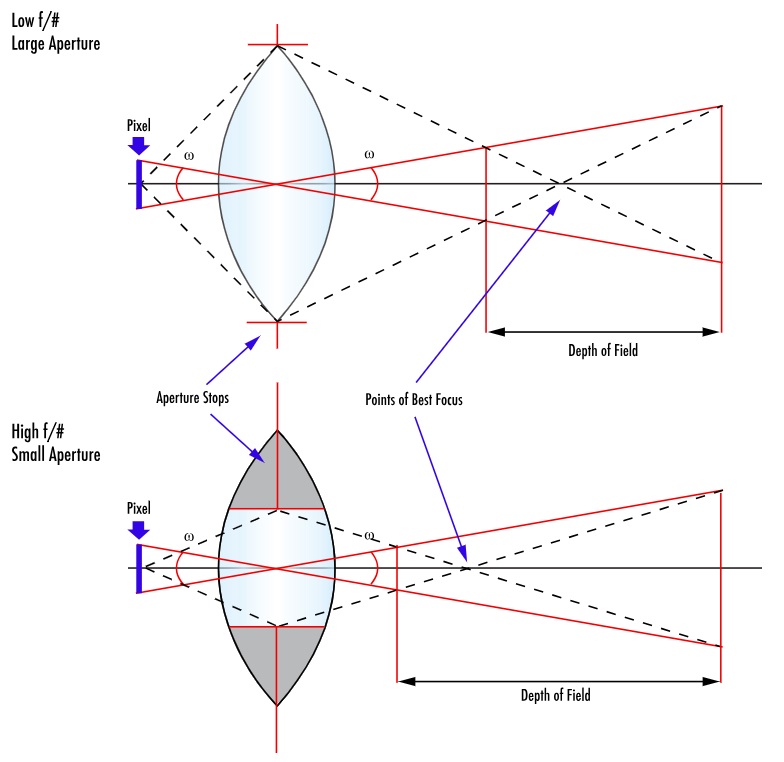
Per the illustration below, a large aperture restricts DoF, while a small aperture maximizes the DoF. Please take a moment to compare the upper and lower variations in this diagram:
If we maximize depth of field…
So let’s pursue maximizing depth of field for a moment. Narrow the aperture to the smallest setting (the largest F-number), and presto you’ve got maximal DoF! Done! Hmm, not so fast.
First challenge – do you have enough light?
Narrowing the aperture sounds great in theory, but for each stop one narrows the aperture, the amount of light is halved. The camera sensor needs to receive sufficient photons in the pixel wells, according to the sensor’s quantum efficiency, to create an overall image with contrast necessary to process the image. If there is no motion in your application, perhaps you can just take a longer exposure. Or add supplemental lighting. But if you do have motion or can’t add more light, you may not be able to narrow the aperture as far as you hoped.
Second challenge – the Airy disk and diffraction
When light passes through an aperture, diffraction occurs – the bending of waves around the edge of the aperture. The pattern from a ray of light that falls upon the sensor takes the form of a bright circular area surrounded by a series of weakening concentric rings. This is called the Airy disk. Without going into the math, the Airy disk is the smallest point to which a beam of light can be focused.
And while stopping down the aperture increases the DoF, our stated goal, it has the negative impact of increasing diffraction.
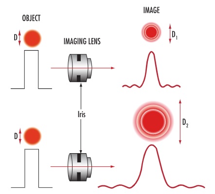
Courtesy Edmund Optics
Diffraction limits
As focused patterns, containing details in your application that you want to discern, near each other, they start to overlap. This creates interference, which in turn reduces contrast.
Every lens, no matter how well it is designed and manufactured, has a diffraction limit, the maximum resolving power of the lens – expressed in line pairs per millimeter. There is no point generating an Airy disk patterns from adjacent real-world features that are larger than the sensor’s pixels, or the all-important contrast needed will not be achieved.

High magnification example
Suppose you have a candidate camera with 3.45um pixels, and you want to pair it with a machine vision lens capable of 2x, 3x, or 4x magnification. You’ll find the Airy disk is 9um across! Something must be changed – a sensor with larger pixels, or a different lens.
As a rule of thumb, 1um resolution with machine vision lenses is about the best one can achieve. For higher resolution, there are specialized microscope lenses. Consult your lensing professional, who can guide you through sensor and lens selection in the context of your application.
Lens data sheets
Just a comment on lens manufacturers and provided data. While there are many details in the machine vision field, it’s quite transparent in terms of standards and performance data. Manufacturers’ product datasheets contain a wealth of information. For example, take a look at Edmund Optics lenses, then pick any lens family, then any lens model. You’ll find a clickable datasheet link like this, where you can see MTF graphs showing resolution performance like LP/mm, DOF graphs at different F#s, etc.
Takeaway
Per the blog’s title, Depth of Field is a balancing act between sharpness and blur. It’s physics. Pursue the links embedded in the blog, or study optical theory, if you want to dig into the math. Or just call us at 987-474-0044.
1st Vision’s sales engineers have over 100 years of combined experience to assist in your camera and components selection. With a large portfolio of lenses, cables, NIC cards and industrial computers, we can provide a full vision solution!