What is TDI? Time Delay Integration?

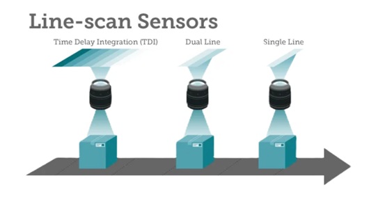
TDI is based on the concept of accumulating multiple exposures of the same (moving) object, effectively increasing the integration time available to collect incident light. The object motion must be synchronized with the exposures to ensure a crisp image.

Line scan sensors are available for diverse applications – Courtesy Teledyne DALSA

Context

If an object were stationary, and one wasn’t in a hurry, one could just do a longer exposure in order to achieve an ideally saturated image. But the object in question is in fact moving. And it’s a line scan application. Each line exposure is extremely fast, so there’s not much opportunity to accumulate sufficient light into the sensor.

Candidate solutions

Use “faster” sensor that is more sensitive in low light situations? Conceptually plausible but not always available relative to speed of motion and available light.

Introduce artificial light? Usually one already adds concentrated light with line scan, but for challenging applications it may not be sufficient… relative to the speeds one hopes to attain.

Use Time Delay Integration (TDI) to build up final image as composite from multiple exposures carefully synchronized to object’s motion. Key concept: the object is moving anyway, so take advantage of that movement as an opportunity to get multiple “looks” at the same slice of the object. A variation on “when given lemons make lemonade”.

See the video below for an illustrative simulation. The conceptual application is mail processing, where the goal is to read whether a letter is stamped, with which denomination of postage, all while the letter is moving at continuous speed along a conveyor belt, lit only by ambient or low intensity light.

Courtesy Teledyne DALSA

The memory summing of the successive exposures builds the readout image.

Benefits

Speed: You can increase the speed of the target object or inspection web, improving overall throughput. This alone may be a huge competitive advantage.

Lower lighting costs: Get by with just one instead of two lights, and perhaps just a modest light rather than a high-intensity one.

Signal to noise ratio: SNR is improved.  Since multiple exposures are summed, useful image signal increases while random noise is reduced. This gives cleaner images and better defect detection.

Tradeoffs

Clearly sufficient synchronization must be achieved for TDI to work effectively. Thankfully the synchronization doesn’t have to be perfect – a TDI device can comfortably tolerate a 2-4% velocity mismatch between inspection web and imager. This is not difficult to achieve using a web-mounted encoder to supply a sync signal to the camera, even with webs that change speed. There are thousands of successful implementations.


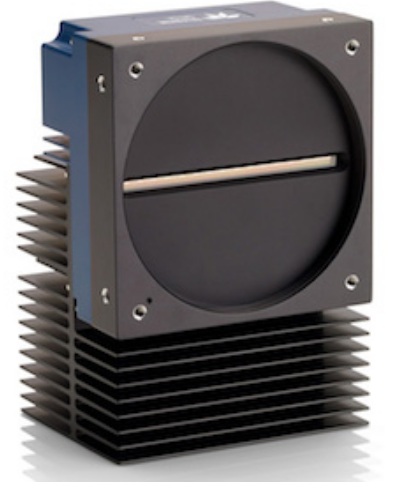
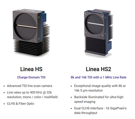
For a wide range of line scan products, the the Teledyne DALSA Linea families. For TDI in particular, drill in on the Linea HS and Linea HS2 products.

Applications

Typical applications include, but are not limited to:

  • Semiconductor wafer inspection
  • High-density interconnect inspection
  • Quality control on flat panel displays
  • Some life science applications

In a nutshell, if it’s “light starved” and line scan, TDI can be the answer.

1st Vision’s sales engineers have over 100 years of combined experience to assist in your camera and components selection.  With a large portfolio of cameraslensescablesNIC cards and industrial computers, we can provide a full vision solution!

About you: We want to hear from you!  We’ve built our brand on our know-how and like to educate the marketplace on imaging technology topics…  What would you like to hear about?… Drop a line to info@1stvision.com with what topics you’d like to know more about.

#Timedelayintegration

#TDI

#Linescan

Six new JAI line scan cameras across two product families

JAI has over 60 years experience in the vision industry, and is likewise a longstanding part of the 1stVision portfolio. JAI produces a diverse range of cameras, including area scan and line scan; across multiple interfaces; and spanning visible, NIR, SWIR, and UV portions of the spectrum.

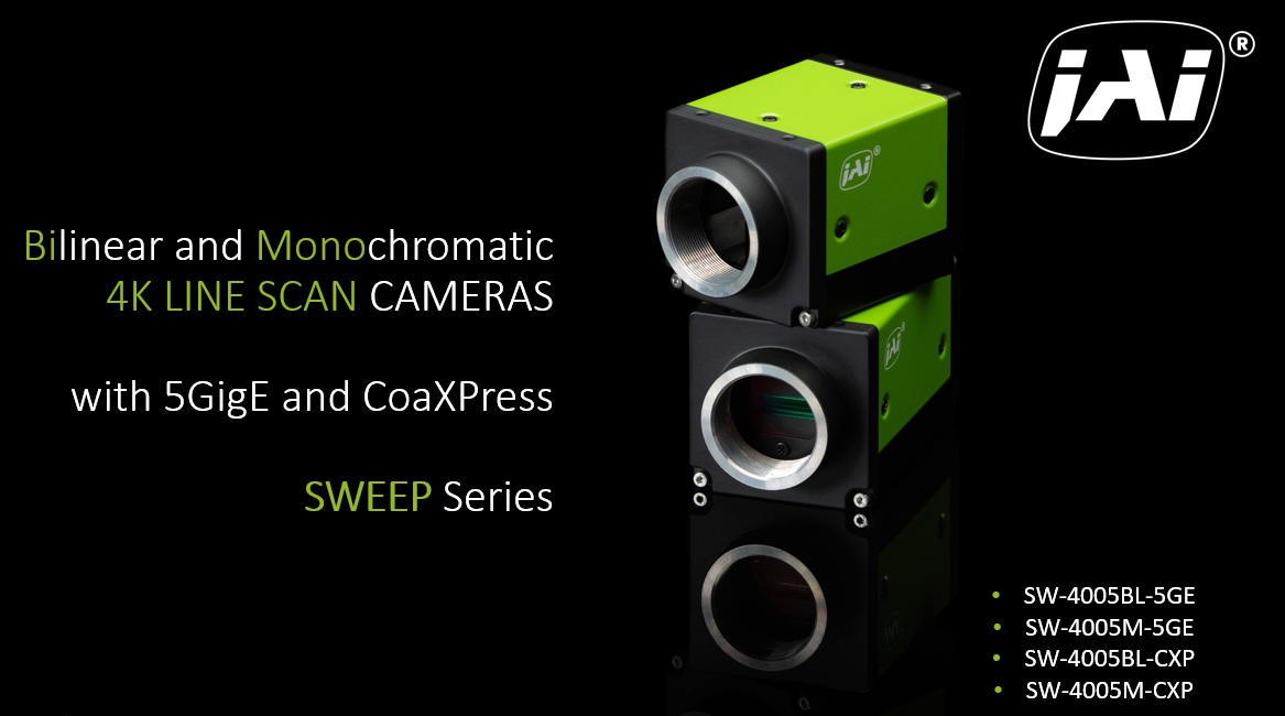
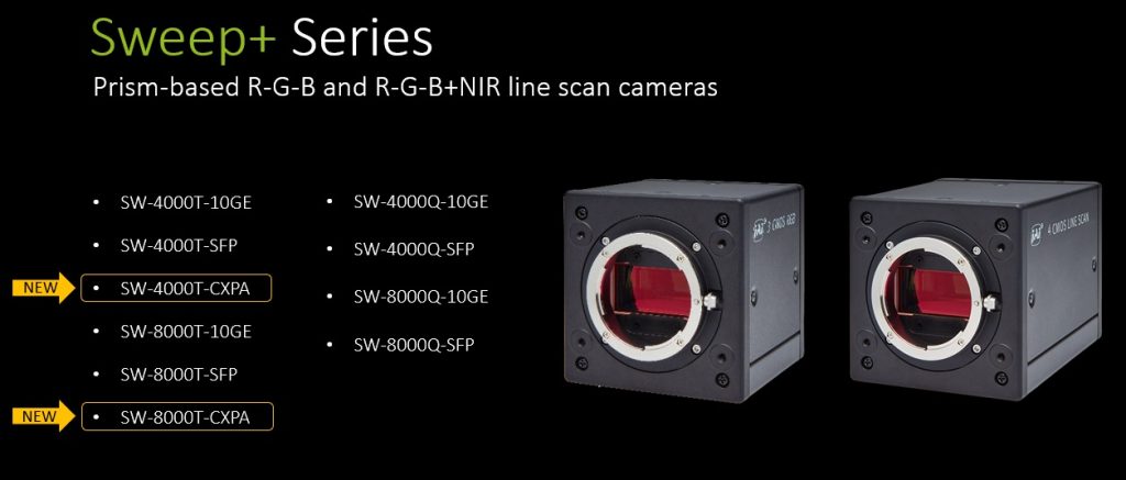
In this article we announce six new line scan camera models: 4 in the Sweep series at 4k each; and 2 in the Sweep+ series at 4k and 8k respectively. There’s a niche for every model.

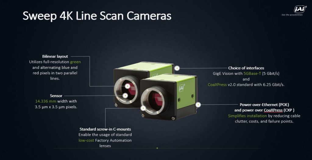
Four new 4k line scan cameras – Courtesy JAI Imaging
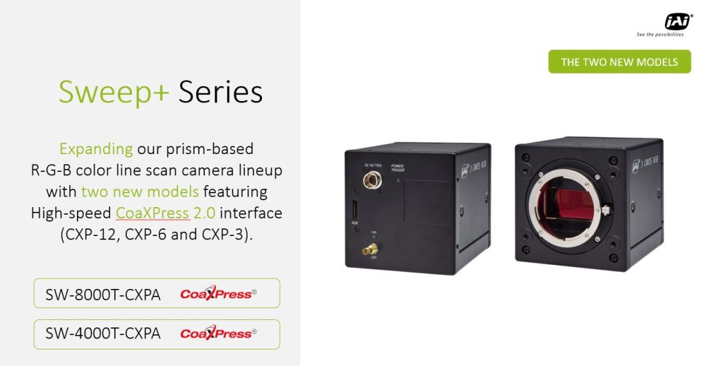
Two new Sweep+ line scan cameras – one 4k one 8k – Courtesy JAI Imaging

Four new 4k line scan Sweep models; Two new Sweep+ models incl. 8k

At the risk of information overload, we’ve bundled this product release update of six new camera models across two product families into a single article. We hope the reader appreciates the compare-and-contrast approach as a way to understand the value proposition for each camera/family.

When you need line scan it’s nice to have options

While area scan sensors with big 2D pixel array outputs are right for some applications, line scan is a better fit for others. In particular, if the object being imaged is essentially continuous, line scan can be an effective way to take narrow image slices with a lower cost 1D sensor that’s long in just the dimension that maps to the object width. Movement of the object (or sensor) together with successive slices then creates the second dimension.

The 1stVision Knowledge Base offers illustrated articles on line scan topics, including How to Calculate Line Rate Based on Conveyor Speed and Polarization Techniques with Line Scan Cameras. Now on to the new camera models!

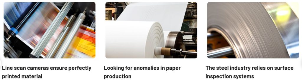
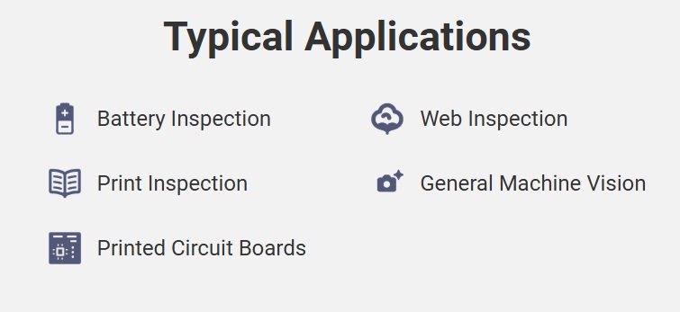
Example line scan applications – Courtesy JAI Imaging

JAI’s Sweep line scan cameras vs. Sweep+

JAI’s Sweep line scan cameras include a wide offering of monochrome, bilinear, and trilinear models, at 2K, 4K, 8K, and 16K. Interface options include 5GigE, 10GigE and CoaXPress. If you need color sensing, the bilinear approach is an affordable approach, and often plenty good enough. For true color capture, the trilinear sensors are superior – if needed.

Sweep+ cameras, as suggested by the + suffix, are JAI’s top of the line color and multispectral line scan products. The beam-splitter prism optics, together with three (color only models) or four (color plus NIR) sensors, deliver high-precision color resolution. Due to the data volumes generated, the Sweep+ cameras use CoaXPress, 10GigE, and CameraLink interfaces to achieve line rates suitable to the respective sensor sizes and anticipated applications.

Click to contact
Give us some brief idea of your application and we will contact you to discuss camera options.

Mini-tutorial on single sensor vs. multi-sensor color imagin

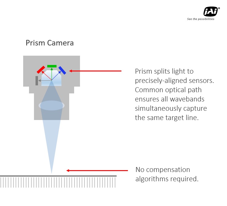
While Bayer filters or equivalent provide single sensor color, that’s good enough for some applications, there is some loss of color resolution via that inherent physical interpolation. So demanding applications take advantage of separate sensors for each segment of the spectrum, using a prism to separate wavelengths. The resulting camera is physically larger to accommodate the the prism, extra sensors, and electronics – but the best possible color performance is achieved.


A deeper dive on the new Sweep cameras

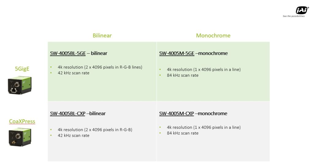
At-a-glance overview of the Sweep 4k cameras – Courtesy JAI Imaging

Monochrome line rates are 2x that of the bilinear color models

… because there is a single monochrome pixel mapped to the target object’s corresponding area.

Courtesy JAI Imagine

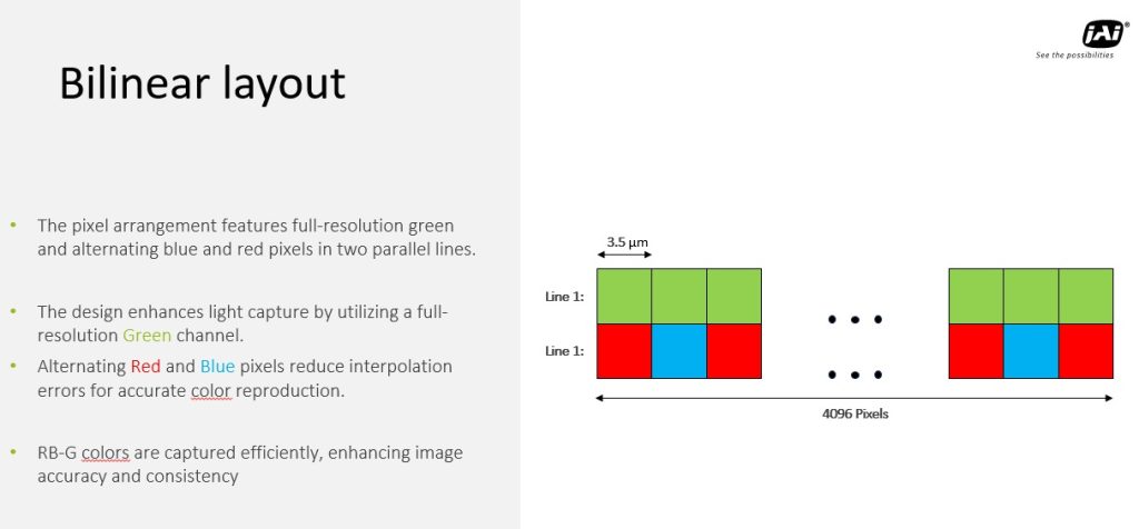
But if you need color the bilinear approach is an efficient way to do it, since there are only two rows of data transmitted for every real-space row imaged….

A peak at the bilinear approach to color line scan imaging

Courtesy JAI Imaging

Other JAI Sweep camera features

Keystone correction, aka tilted view correction, onboard the camera

Trigger-width dynamic exposure control

Resume-scanning control for stop-start motion

Trigger delay

… and more

Drill in to JAI Sweep camera models and datasheets. Or let us guide you.


More details on JAI’s new Sweep+ line scan cameras:

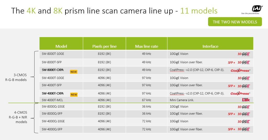
A 4k and and 8k model, both with CoaXPress interfaces – Courtesy JAI Imaging
The two new models round out the Sweep+ lineup – Courtesy JAI Imaging
Precise prism optical design yields superior images – Courtesy JAI Imaging
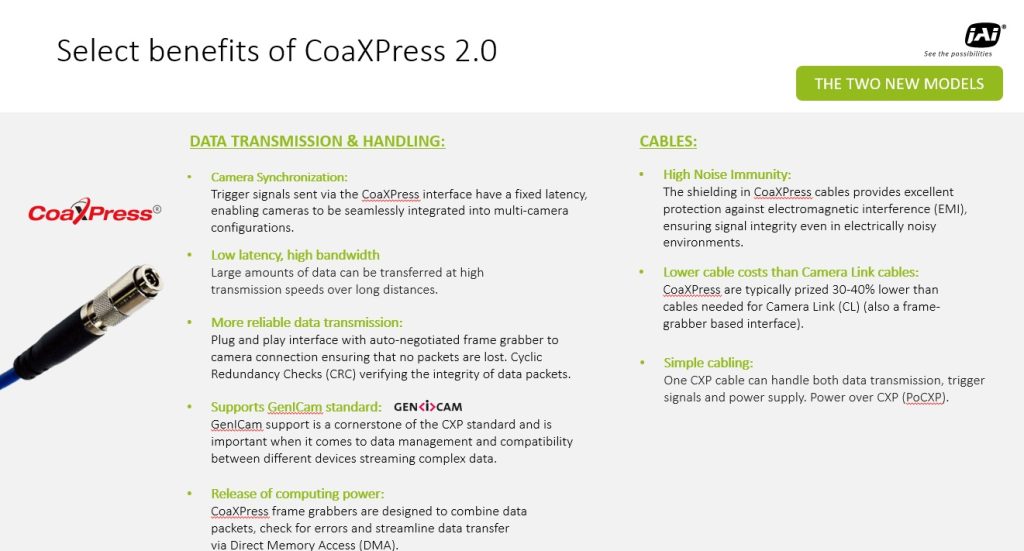
Some of the key benefits of CoaXPress – Courtesy JAI Imaging

And yet more features…

You get the idea… Sweep+ is a remarkable camera family. There are even more features to find in the Sweep+ product details and datasheets. Or just call us at 878-571-5683 for expert assistance. Tell us about your application requirements and we’ll guide you to an optimal camera. Lighting, lenses, filters, cables, and software too.

1st Vision’s sales engineers have over 100 years of combined experience to assist in your camera and components selection.  With a large portfolio of cameraslensescablesNIC cards and industrial computers, we can provide a full vision solution!

About you: We want to hear from you!  We’ve built our brand on our know-how and like to educate the marketplace on imaging technology topics…  What would you like to hear about?… Drop a line to info@1stvision.com with what topics you’d like to know more about.

Teledyne DALSA AxCIS Contact Image Sensor Applications

Why read this blog?

  1. To learn what kinds of applications are well-suited for a Contact Image Sensor
  2. To see the unique features only found in the Teledyne DALSA AxCIS series

You already know (or can catch up quickly):

Contact Image Sensors don’t actually contact the things they are imaging. But they get to within 15 mm = 0.59 inches! So they are ideal for space-constrained applications.

And they aren’t interchangeable with line scan cameras, they are a variant on line scan concepts. They share the requirement that “something is moving” and that the sensor array is a single row of pixels.

contact us

Applications for Contact Image Sensing

Courtesy Teledyne DALSA

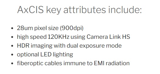
Why Teledyne DALSA AxCIS in particular?

You may want to review the whole Teledyne DALSA AxCIS series, and the datasheet details. Go for it! Geek out. Full transparency as always.

Or maybe you’d like a little help on what we think is special about the Teledyne DALSA AxCIS series?

T2IR – Trigger to Image Reliability

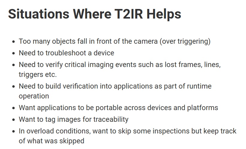
This is a Teledyne DALSA proprietary innovation that helps to de-mystify what’s happening inside a complex vision system. It uses hardware and software to improve reliability. In high level terms, T2IR monitors from trigger through image capture, and on to host memory transfer, aiming to protect against data loss. And to provide insights for system tuning if needed. T2IR is compatible with many Teledyne DALSA cameras and frame grabbers – including the AxCIS series.

Courtesy Teledyne DALSA

If you prefer it written out:

Courtesy Teledyne DALSA

1st Vision’s sales engineers have over 100 years of combined experience to assist in your camera and components selection.  With a large portfolio of cameraslensescablesNIC cards and industrial computers, we can provide a full vision solution!

About you: We want to hear from you!  We’ve built our brand on our know-how and like to educate the marketplace on imaging technology topics…  What would you like to hear about?… Drop a line to info@1stvision.com with what topics you’d like to know more about

How to calculate line rate on a line scan camera based on conveyor speed

Unless one calculates and sets the line rate correctly, there’s a risk of blur and sub-optimal performance. And/or purchasing a line scan camera that’s not up to the task; or that’s overkill and costs you more than would have been needed.

Line Scan concept – Courtesy Teledyne DALSA

Optional line scan review or introduction

Skip to the next section if you know line scan concepts already. Otherwise…

Perhaps you know about area scan imaging, where a 2D image is generated with a global shutter, exposing all pixels on a 2D sensor concurrently. And you’d like to understand line scan imaging by way of comparing it to area scan. See our blog What is the difference between an Area Scan and a Line Scan Camera?

30 minute informative overview of Line Scan imaging – Courtesy Teledyne DALSA

Maybe you prefer seeing a specific high-end product overview and application suggestions, such as the Teledyne DALSA 16k TDI line scan camera with 1MHz line rate. Or a view to tens of different line scan models, varying not only by manufacturer, but by sensor size and resolution, interface, and whether monochrome or color.

Either you recall how to determine resolution requirements in terms of pixel size relative to defect size, or you’ve chased the link in this sentence for a tutorial. So we’ll keep this blog as simple as possible, dealing with line rate calculation only.

Line scan cameras – Courtesy Teledyne DALSA

Calculate the line rate

Getting the line rate right is the application of the Goldilocks principle to line scanning.

Line rate too slow…Line rate too fast…
Blurred image if due to too long exposure, and/or missed segments due to skipped “slices”Oversampling can create confusion by identifying the same feature as two distinct features
Why we need to get the line rate rate right

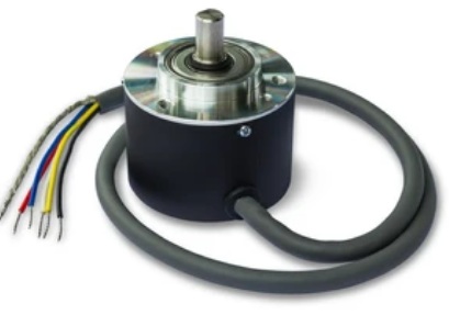
A rotary encoder is typically used to synchronize the motion of the conveyor or web with the line scan camera (and lighting if pulsed). Naturally the system cannot be operated faster than the maximum line speed, but it may sometimes operator more slowly. This may happen during ramp up or slow down phases – when one may still need to obtain imaging – or by operator choice to conserve energy or avoid stressing mechanical systems.

Naming the variables … with example values

Resolution A = object space correlation to sensor; FOV / pixel array; e.g. if 550mm FOV and 2k sensor = 550/2000 = 0.275 pixels per mm

Transport speed T = mm per sec; e.g. 4k / 1mm yields rate of motion

Sampling frequency F = T / A; for example values above F = 4000 / 0.275 = 14545.4545 = 14.5kHz; spelled out: Frequency = Transport_speed / Pixel_spatial_resolution (what 1 pixel equals in target space)

For the example figures used above, a line scan camera with 2k resolution and a line scan frequency of about 14.5 kHz will be sufficient.

Download spreadsheet with labeled fields and examples:

Just click here, or on the image below, to download the spreadsheet calculator. It includes clearly labeled fields, and examples, as the companion piece for this blog:

Not included here… but happy to show you how

We’ve kept this blog intentionally lean, to avoid information overload. Additional values may also be calculated, of course, such as:

Data rate in MB / sec: Useful to confirm camera interface can sustain the data rate

Frame time: The amount of time to process each scanned image. Important to be sure the PC and image processing software are up to the task – based on empirical experience or by conferring with software provider.

1st Vision’s sales engineers have over 100 years of combined experience to assist in your camera and components selection.  With a large portfolio of cameraslensescablesNIC cards and industrial computers, we can provide a full vision solution!

About you: We want to hear from you!  We’ve built our brand on our know-how and like to educate the marketplace on imaging technology topics…  What would you like to hear about?… Drop a line to info@1stvision.com with what topics you’d like to know more about