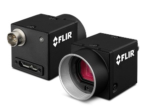
New to the 1stVision portfolio, FLIR Blackfly S are available in compact housed and board-level models, with lossless compression, achieving both high speed and high image quality.
Features and Benefits
USB3 Vision and GigE Vision interface models
Sony Pregius S and ON Semi CMOS sensors for high sensitivity, low noise image quality
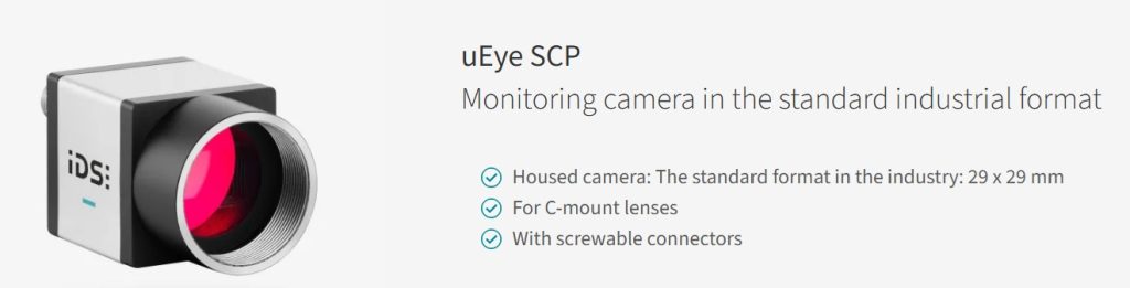
Compact 29 × 29 mm “ice cube” form factor simplifies integration in tight spaces
Wide resolution range (<1 MP to 20+ MP) supports speed or precision optimization
Advanced on-camera image processing include color correction, lossless compression, lens shading correction
Advanced camera controls (sequencer, timers, counters, events) enable precise automation
Develop Once, Deploy Everywhere
With tens of different models of FLIR Blackfly S, cameras, Teledyne Vision Solutions emphasizes “develop once, deploy everywhere”. Since each housed model has the same form factor, varying only by sensor, from < 1MP to > 24MP, the same SDK, software, and interface deploys seamlessly. Whether you want to increase resolution at an existing camera position, or roll out cameras at new positions and new applications, the breadth of this camera series really helps customers scale easily.
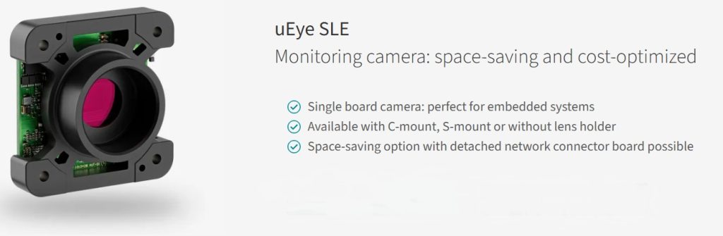
Per the video below, board-level cameras can be deployed in diverse configurations, but share the same board dimensions, SDK options, and interfaces.
Typical Applications
- Automated optical inspection (AOI)
- Industrial machine vision inspection systems
- Robotics guidance and pick-and-place
- Electronics and semiconductor inspection
- Medical and life sciences imaging
- Barcode reading and logistics automation
- Embedded vision and OEM integration
- Intelligent traffic systems and transportation imaging
- Electronics and semiconductor inspection
- Food and packaging inspection
- Scientific and laboratory imaging

Additional benefits
Lens costs typically low: Thanks to many Blackfly S cameras using Sony Pregius S sensors, small pixel sizes enable high resolution packed into a small sensor. This means lenses can be physically smaller, which saves weight and materials, and typically translates to lower costs.
Reduced lighting requirements: Another benefit of highly-responsive sensors is that ambient light may be all that’s needed. Or less ambitious artificial lighting. Another possible cost advantage.
Synchronize by PTP: For multi-camera applications, often it’s required to synchronize two or more cameras. Precision Time Protocol (PTP) allows that to happen through the camera network cabling, without additional cable costs or complexity management.
Can be used with Sapera LT (Teledyne Dalsa SDK), so if you’re using DALSA Nano and find a model from the FLIR line up, you can make an easy switch.
Series extended – new models
Even if you thought you knew the Blackfly S series, new models joined the family. For example the BFS-PGE-50Y2 is available in both monochrome and color, with Sony AR0521 1/2.5″ CMOS sensor, 2.2 um pixels, and 24 FPS at 5 MP. With a CS-mount it’s ideal for flexible optics choices and system integration.
Call us at 978-474-0044. We can guide you to the optimal sensor, camera, and interface for your application requirements. We’ve also got you covered for lensing, lighting, software, and accessories.

1st Vision’s sales engineers have over 100 years of combined experience to assist in your camera and components selection. With a large portfolio of cameras, lenses, cables, NIC cards and industrial computers, we can provide a full vision solution!
About you: We want to hear from you! We’ve built our brand on our know-how and like to educate the marketplace on imaging technology topics… What would you like to hear about?… Drop a line to info@1stvision.com with what topics you’d like to know more about.
#FLIR
#Blackfly
#TeledyneDALSA
#TeledyneVisionSolutions