Optical metrology is an application area within machine vision focused on precise measurement using controlled optics, lighting, cameras, and calibration. Telecentric lenses are designed to maintain constant magnification over a defined depth range, reducing perspective error.
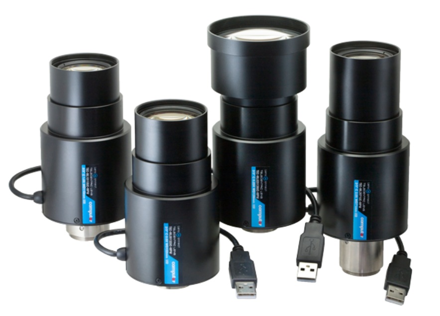
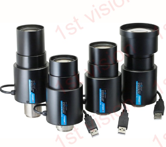
Computar LensConnect telecentric motorized lenses are the first in the industry to combine these features. That brings precision telecentric optics with intelligent remote focus control for high-accuracy industrial imaging and measurement applications.
LensConnect USB powered motorized telecentric lenses – Courtesy Computar
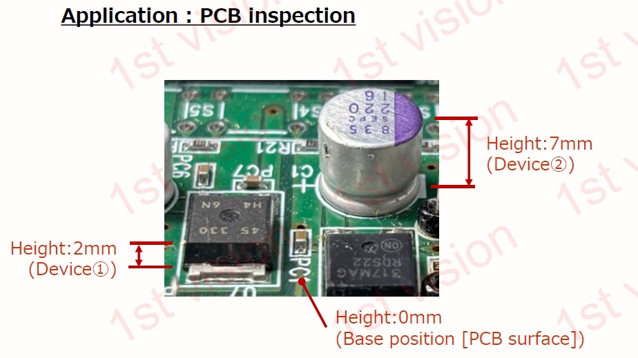
Example application: PCB Inspection
Consider the following application:
Courtesy Computar
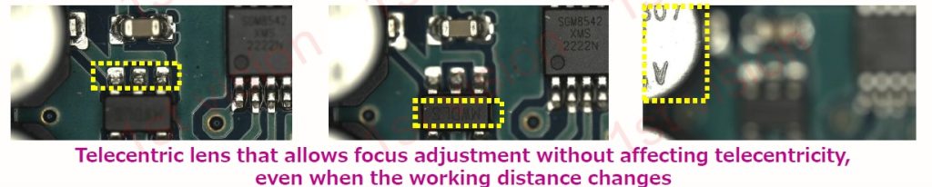
The application needs to BOTH measure the height of all three indicated components AND to OCR read/verify/record the markings on the components. That requires both telecentricity and focus control.
Courtesy Computar
Motorized automated focus is key differentiator
In the short 35 second video below, one can see how lens controls are parameterized to automatically optimize focus, adapting to variable conditions.
Four different magnification options
There are 4 different lens models in the series, with magnifications of:
Ideal for metrology, semiconductor, and electronics inspection
Simplifies remote setup and multi-camera calibration systems
1stVision is pleased to have these LensConnect motorized telecentric lenses in our portfolio, along with all the other Computar lenses. Call us at 978-474-0044.
About you: We want to hear from you! We’ve built our brand on our know-how and like to educate the marketplace on imaging technology topics… What would you like to hear about?… Drop a line to info@1stvision.com with what topics you’d like to know more about.
In machine vision, historically there is a preponderance of fixed focal length (FFL) lenses, also know optically as a prime lens. They are less complex to design and manufacture, and are high-performance in terms of image sharpness and ability to accept wide aperture options for low-light applications. FFL lenses are typically are set for a designed FOV and WD and don’t have flexibility on focal lengths. If your application is like that, lucky you.
But my application isn’t like that!
You may have a factory production monitory project, for example. You know the general dimensions of the layout and the approximate camera mounting position. But you have limited time to configure and deliver proof of concept or acceptance testing. so you want to show up with everything you need to achieve good outcomes, instead of guessing wrong on a fixed focal length lens and having to exchange it.
Whatever your planned application, you know the optical “neighborhood” but need the flexibility to fine-tune in the field.
Zoom lens
A zoom lens remains in focus across a range of focal lengths, and is often remotely controlled. Likewise it’s also often motorized. So they tend to be large(ish), heavier, more complex to design, and are more expensive than a fixed-focal length lens.
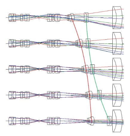
Zoom lens at differing optical magnifications – Courtesy Edmund Optics
In the illustration above, notice how the light rays entering from the right range from a wide field of view (FOV) at the top to a narrow FOV at the bottom. That’s a consequence of the changing focal length. It’s an asset if you need that behavior. Or a liability if you don’t
This blog is about varifocal lenses, so that’s all we’ll say about zoom lenses here. But the “different focal lengths” and “different FOV” concepts also apply to varifocal lenses, so it’s worth noting points of overlap.
Varifocal lens
A varifocal lens is designed to hit the sweet spot between fixed focal length vs. zoom. By spanning a (modest) range of focal lengths, a varifocal lens can be adapted in the field to optimize for observed conditions.
You might not know at design time exactly what final focal length you’ll choose, so a range of coverage lets you tune as you deploy and run acceptance tests. It also means the same lens could be used for a year or more in one setting – then loosen a set screw, refocus, and tighten the set screw and the same lens performs great in the new context.
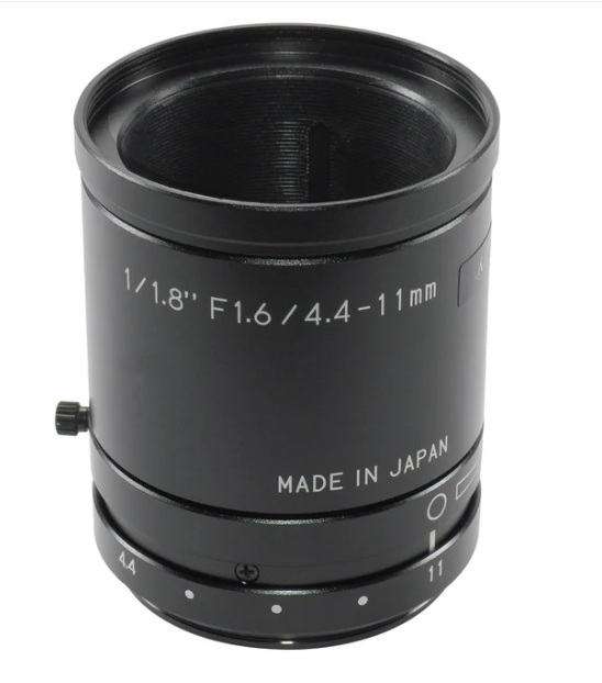
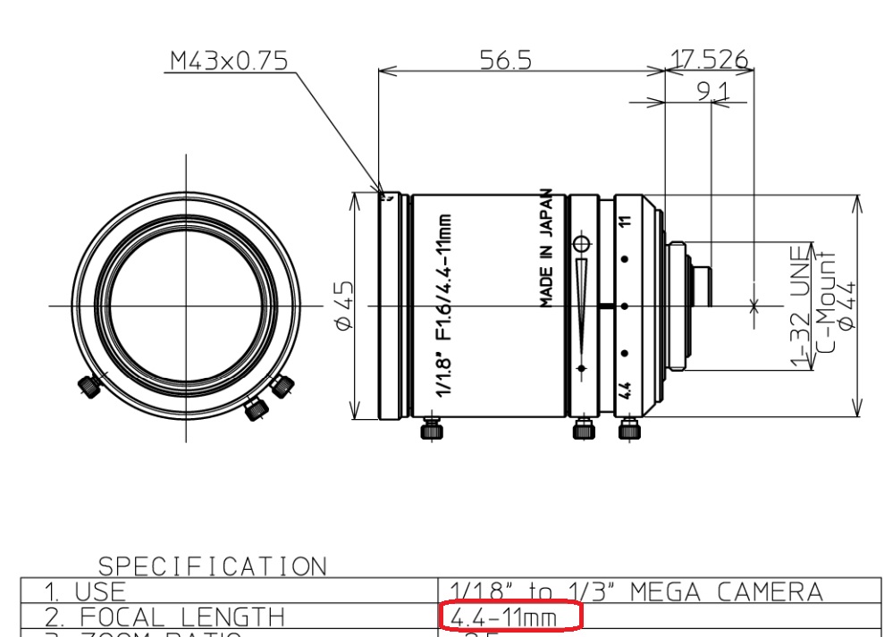
Example: per red ellipses markup, this lens offers focal lengths from 4.4 – 11mm – Courtesy Kowa
But unlike a big motorized zoom, the varifocal lens is often* manually adjusted. And it’s typically modest in size, weight, design complexity, and cost.
(*) EXCEPTION! The Optotune electrically tunable series describe below uses liquid lens technology for autofocus within milliseconds.
Enough concept already – what varifocal lenses are available?
Below we present and link to three different varifocal product lines carried by 1stVision. We sequence by alphabetical order, but each series has its own value proposition, depending on your application needs:
Kowa LMVZ Varifocal Lenses
Kowa’s LMVZ varifocal lenses are designed for machine vision, industrial inspection, and surveillance applications. Their adjustable focal length design allows integrators to fine-tune field of view without changing lenses.
Kowa LMVZ varifocal lenses – optionally with IR correction for VIS + SWIR – Courtesy Kowa
Optotune Focus Tunable Lenses
Optotune is an industry leader in focus tunable lenses. Many are electrically tunable, utilizing liquid lens technology. They also offer a manually tunable lens.
A focus tunable lens – Courtesy Optotune
Unlike manually tunable varifocals, the EL series offers fast, precise autofocus in milliseconds with no moving mechanics.
Tamron Vari-Focal Lens Series
The Tamron vari-focal series is designed for high-resolution IP and security surveillance cameras. These lenses offer flexible focal length adjustment for both wide-area coverage and detailed zoom.
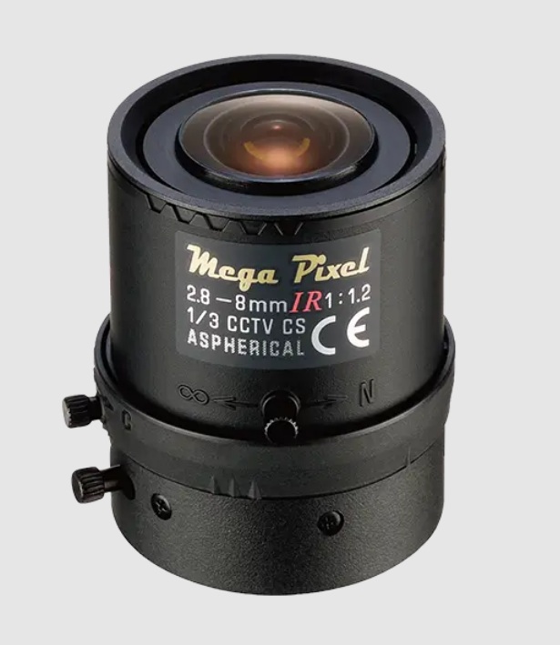
Mega Pixel varifocal lens series – Courtesy Tamron
Select IR-corrected models enable true day/night performance, while compact, durable construction ensures dependable operation in commercial, industrial, and municipal security installations.
Optics is partly physics and science…
But it’s also engineering, and performance requirements, and budget, and experiential knowledge. If you’ve got a lot of all that in your wheelhouse, just call for a quote at 978-474-0044. Or if you’d like some help in choosing, call that same number and tell us a little about your application. Either way, we’re here for you. For lenses, cameras, and more.
About you: We want to hear from you! We’ve built our brand on our know-how and like to educate the marketplace on imaging technology topics… What would you like to hear about?… Drop a line to info@1stvision.com with what topics you’d like to know more about.
All of us machine vision practitioners know a thing or two about camera lenses. Some of us are optical engineers. Others are self-taught through reading and experience. Others let their systems designers choose the lens.
Ever need a fast focus change?
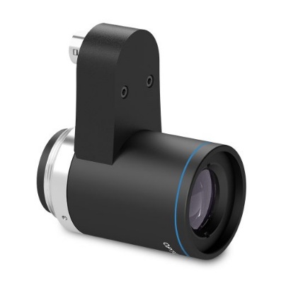
If your application does fine with a fixed focal lens, or a mechanically adjustable focus, that’s great. But some applications benefit from – or only become possible with – the ability to rapidly tune the focus. Enter liquid lenses, like Opto Engineering’s EL5MP and EL12MP.
EL5MP liquid lens – Courtesy Opto Engineering
Liquid lenses – from theory to commercial availability
Leonhard Euler (Euler’s equations, anyone?) did groundbreaking work in fluid dynamics in the 1700s. In 1859 Thomas Sutton used a glass sphere filled with water to create a lens. So the concepts for liquid lenses aren’t new. But they’ve only been commercialized in the last 20 years. Here’s a short video (3 minutes) featuring an early leader in liquid lenses, with a nice overview of the key concepts:
From theory to practice – a 5MP and 12MP liquid lens series
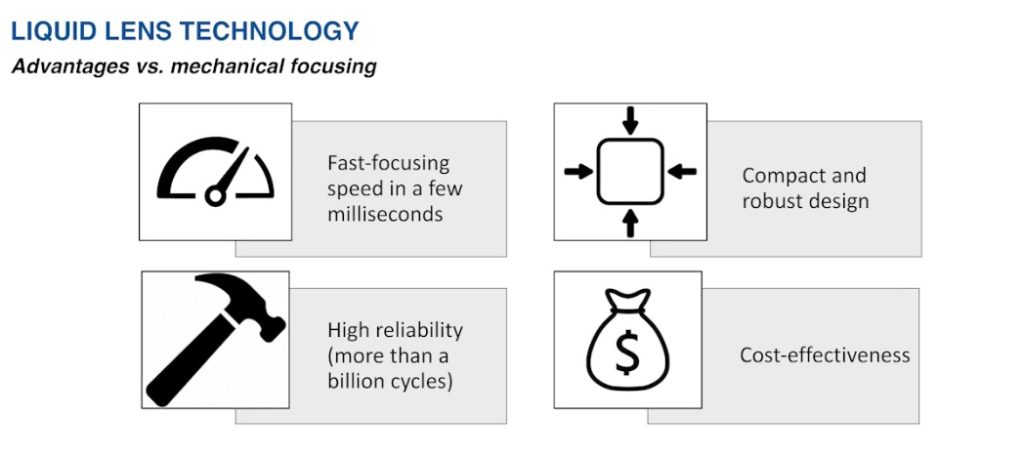
If you need fast focus (a few milliseconds) and high reliability (more than a billion cycle lifetime), Opto Engineering offers both a 5MP liquid lens series as well as a 12MP series. Each series provides several focal length options:
6mm for the 5MP series only
8mm for the 5MP series only
12mm for BOTH the 5MP and 12MP series
16mm for BOTH the 5MP and 12MP series
25mm for BOTH the 5MP and 12MP series
35mm for 12MP series only
Working distance coverage range
Across the two series, there are working distances on the near side from 60 – 200mm, depending on the specific model. At the far side the WD goes to infinity for each of the lenses. See the product comparison tables and data sheets at Opto Engineering EL5MP and EL12MP respectively.
More specs
The 5MP series is designed for sensors up to 2/3″. One exception: the 6mm focal length model is for sensors up to 1/1.8″.
The 12MP series is for sensors up to 1.1″.
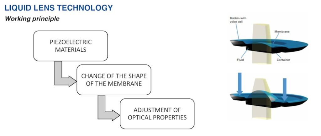
Basis for liquid lens – Courtesy Opto Engineering
Liquid lens advantages vs. mechanical focus – Courtesy Opto Engineering
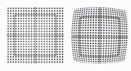
Low distortion is another advantage
Liquid lens image (left) has almost no distortion – another huge benefit – Courtesy Opto Engineering
What are the focus demands of your application?
Do you know your application’s focus requirements? Could you build a more effective application with faster focus? Reduce lens service and replacement intervals by switching from a mechanical to a liquid lens? Call us at 978-474-0044 to discuss options or get a quote.
Video presentation on Opto Engineering liquid lenses
Tradeshow presentation runs 14 minutes, if you want to do a deeper dive that way:
Courtesy Opto Engineering
Note: Over the years, various operating principles for liquid lenses have been introduced.
About you: We want to hear from you! We’ve built our brand on our know-how and like to educate the marketplace on imaging technology topics… What would you like to hear about?… Drop a line to info@1stvision.com with what topics you’d like to know more about.
While we humans can only see what we’ve named to be visible light, bees can see UV light! Some camera sensors register IR wavelengths! Some cameras can sense both visible light and on through NIR and SWIR.
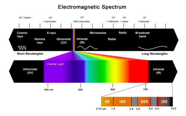
In this piece we focus on applications that benefit from combined VIS-SWIR solutions, from 400 nm through 2.5 nm.
Deconstructing the electromagnetic spectrum into it’s commonly known constituent regions
Example applications
Just to whet the appetite, consider the 4 sets of image pairs below. In each case, the leftmost image was captured with visible wavelengths, while the righthand image utilized SWIR portions of the spectrum. These pairs were chosen to highlight the compelling power of SWIR to identify features that are not apparent in the visible portion of the spectrum.
VIS-SWIR image pairs – Courtesy Allied Vision – a TKH company
For certain applications, one wouldn’t need the human-visible images, of course, as with machine vision the whole point is to automate the image processing and corresponding actions. So for counterfeit banknote detection, bottle fill level monitoring, materials identification, or crop monitoring, one might just design for the SWIR portion of the spectrum and ignore the VIS.
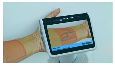
Vein imaging application overlays SWIR image of veins into visible image of patient forearm –Image courtesy TAMRON
But some applications might benefit from both the VIS and the SWIR images. For example, the vein imaging application might require a VIS reference image as well as a SWIR-specific image, for patient education and/or medical records.
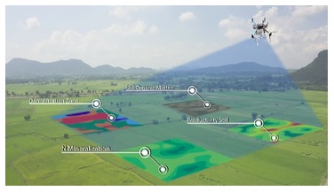
Monitor moisture levels in crops from airborne drone – Image courtesy TAMRON
For the crop monitoring application above, the VIS spectrum clearly orients trees, hills, buildings, and roadways. Meanwhile pseudo-color-mapping shows the varied moisture levels as sensed in the SWIR portion of the spectrum.
The range of potential applications combining VIS and SWIR is staggering. One can improved on one’s own or a competitor’s previous application. Or innovate something altogether new.
Sensors that register both VIS and SWIR wavelengths
Sony’s IMX992 and IMX993 sensors utilize Sony’s SenSWIR technology, such that a single sensor and camera may be deployed across the combined VIS and SWIR portions of the spectrum. Without such sensors, a VIS SWIR solution would require at least two separate cameras – one each for VIS and SWIR, respectively. That would add unnecessary expense, takes up more space, and require camera and image synchronization.
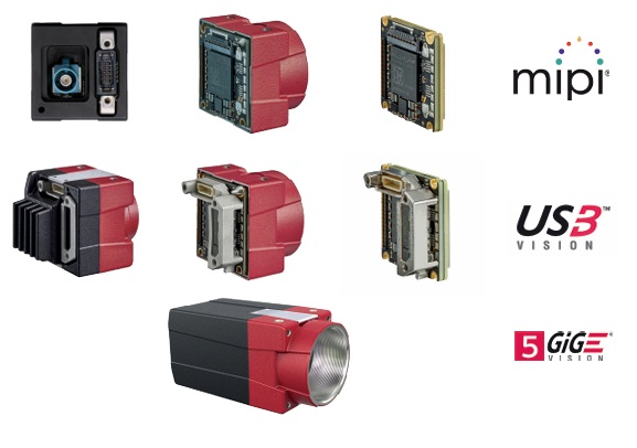
Now there are cameras, such as several in Allied Vision’s Alvium series, in which Sony’s SenSWIR sensors are embedded. With several interface options, including mipi, USB3 Vision, and 5GigE Vision:
Mipi, USB3 Vision, and 5GigE Vision interface options – Courtesy Allied Vision – a TKH Company
Lens manufacturers doing their part
One of the beauties of the free-market system, together with agreements on standards for interfaces and lens mounts, is that each innovator and manufacturer can focus on what he does best. Sensor manufacturers bring out new sensors. Camera designers embed those sensors and provide programming controls, communications interfaces, and lens mounts. And optics professionals design and produce lenses. The benefits from a range of choices, performance options, and price points.
Navitar VIS-SWIR lenses
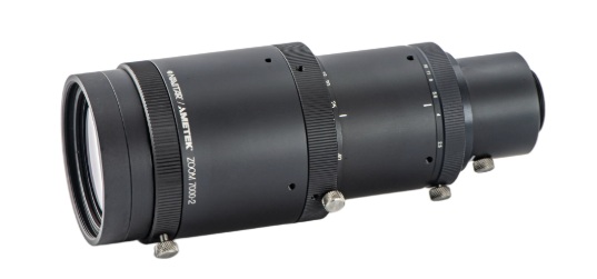
Navitar’s ZOOM 7000-2 macro lens imaging system delivers superb optical performance and image quality for visible and SWIR imaging. Their robust design ensures reliability even in harsh environments. ZOOM 7000-2 macro lenses are ideal for applications, such as machine vision, scientific and medical imaging applications.
ZOOM 7000-2 VIS-SWIR lens – Courtesy Navitar
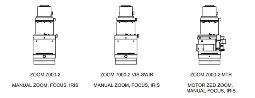
In fact there are three models in the series:
Each model has its application – but only the middle one is designed explicitly for VIS-SWIR – Courtesy Navitar
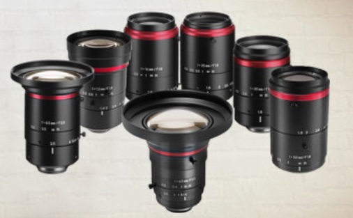
Kowa FC24M multispectral lenses
Kowa’s FC24M C-mount lens series are manufactured with wide-band multi-coating. That minimizes flare and ghosting from VIS through NIR. These lenses are also compelling for a number of other reasons, including wide working range (as close as 15 cm MOD), durable construction, and a unique close distance aberration compensation mechanism.
FC24M C-mount lens series – Courtesy Kowa
That “floating feature” creates stable optical performance at various working distances. Internal lens groups move independently of each other, which optimizes alignment compared to traditional lens design.
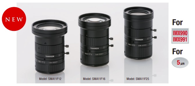
Tamron Wide-band SWIR lenses
Other lensing options include Tamron’s Wide-band SWIR lenses. While the name says SWIR, in fact they are VIS-SWIR. Designed for compatibility with Sony’s IMX990 and IMX991 SenSWIR sensors, you have even more lens choices. Call us at 978-474-0044 if you’d like us to help you navigate to best-fit components in cameras, lensing, and lighting, for your particular application.
About you: We want to hear from you! We’ve built our brand on our know-how and like to educate the marketplace on imaging technology topics… What would you like to hear about?… Drop a line to info@1stvision.com with what topics you’d like to know more about.