Machine vision lights as important as sensors and optics

Lighting matters as much or more than camera (sensor) selection and optics (lensing). A sensor and lens that are “good enough”, when used with good lighting, are often all one needs. Conversely, a superior sensor and lens, with poor lighting, can underperform. Read further for clear examples why machine vision lights are as important as sensors and optics!

Assorted white and color LED lights – courtesy of Advanced Illumination

Why is lighting so important? Contrast is essential for human vision and machine vision alike. Nighttime hiking isn’t very popular – for a reason – it’s not safe and it’s no fun if one can’t see rocks, roots, or vistas. In machine vision, for the software to interpret the image, one first has to obtain a good image. And a good image is one with maximum contrast – such that photons corresponding to real-world coordinates are saturated, not-saturated, or “in between”, with the best spread of intensity achievable.

Only with contrast can one detect edges, identify features, and effectively interpret an image. Choosing a camera with a good sensor is important. So is an appropriately matched lens. But just as important is good lighting, well-aligned – to set up your application for success.

What’s the best light source? Unless you can count on the sun or ambient lighting, or have no other option, one may choose from various potential types of light:

  • Fluorescent
  • Quartz Halogen – Fiber Optics
  • LED – Light Emitting Diode
  • Metal Halide (Mercury)
  • Xenon (Strobe)
Courtesy of Advanced Illumination

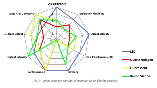
By far the most popular light source is LED, as it is affordable, available in diverse wavelengths and shapes (bar lights, ring lights, etc.), stable, long-life, and checks most of the key boxes.

The other light types each have their place, but those places are more specialized. For comprehensive treatment of the topics summarized here, see “A Practical Guide to Machine Vision Lighting” in our Knowledgebase, courtesy of Advanced Illumination.

Download whitepaper
Download whitepaper

Lighting geometry and techniques: There’s a tendency among newcomers to machine vision lighting to underestimate lighting design for an application. Buying an LED and lighting up the target may fill up sensor pixel wells, but not all images are equally useful. Consider images (b) and (c) below – the bar code in (c) shows high contrast between the black bars and the white field. Image (b) is somewhere between unusable or marginally usable, with reflection obscuring portions of the target, and portions of the (should be) white field appearing more grey than white.

Courtesy of Advanced Illumination

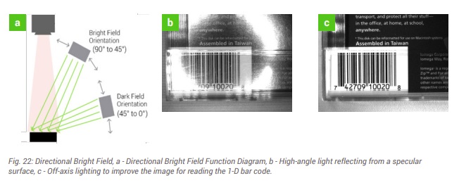
As shown in diagram (a) of Figure 22 above, understanding bright field vs dark field concepts, as well as the specular qualities of the surface being imaged, can lead to radically different outcomes. A little bit of lighting theory – together with some experimentation and tuning, is well worth the effort.

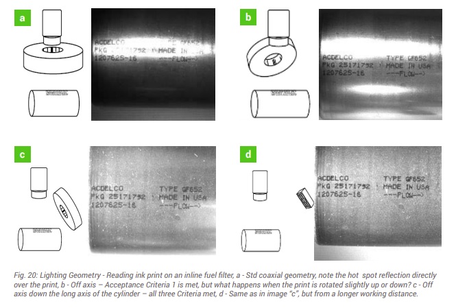
Now for a more complex example – below we could characterize images (a), (b), (c) and (d) as poor, marginal, good, and superior, respectively. Component cost is invariant, but the outcomes are sure different!

Courtesy of Advanced Illumination

To learn more, download the whitepaper or call us at (978) 474-0044.

Contact us

Color light – above we showed monochrome examples – black and white… and grey levels in between. Many machine vision applications are in fact best addressed in the monochrome space, with no benefit from using color. But understanding what surfaces will reflect or absorb certain wavelengths is crucial to optimizing outcomes – regardless of whether working in monochrome, color, infrared (IR), or ultraviolet (UV).

Beating the same drum throughout, it’s about maximizing contrast. Consider the color wheel shown below. The most contrast is generated by taking advantage of opposing colors on the wheel. For example, green light best suppresses red reflection.

Courtesy of Advanced Illumination

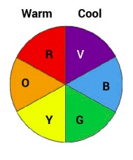
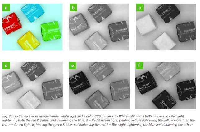
On can use actual color light sources, or white light together with well-chosen wavelength “pass” or “block” filters. This is nicely illustrated in Fig. 36 below. Take a moment to correlate the configurations used for each of images (a) – (f), relative to the color wheel above. Depending on one’s application goals, sometimes there are several possible combinations of sensor, lighting, and filters to achieve the desired result.

Courtesy of Advanced Illumination

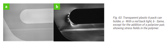
Filters – can help. Consider images (a) and (b) in Fig. 63 below. The same plastic 6-pack holder shown is shown in both images, but only the image in figure (b) reveals stress fields that, were the product to be shipped, might cause dropped product, reduced consumer confidence in one’s brand. By designing in polarizing filters, this can be the basis for a value-added application, automating quality control in a way that might not have been otherwise achievable – or not at such a low cost.

Courtesy of Advanced Illumination

For more comprehensive treatment of filter applications, see either or both Knowledgebase documents:


Powering the lights – should the be voltage-driven or current-driven? How are LEDs powered? When to strobe vs running in continuous modes? How to integrate light controller with the camera and software. These are all worth understanding – or having someone in your team – whether in-house or a trusted partner – who does.

For comprehensive treatment of the topics summarized here, see Advanced Illumination’s “A Practical Guide to Machine Vision Lighting” in our Knowledgebase:

Download whitepaper
Download whitepaper

This blog is intended to whet the appetite for interest in lighting – but it only skims the surface. Machine vision lights as important as sensors and optics. Please download the guide linked just above – to deepen your knowledge. Or if you want help with a specific application, you may draw on the experience of our sales engineers and trusted partners.

1st Vision’s sales engineers have over 100 years of combined experience to assist in your camera and components selection.  With a large portfolio of lensescablesNIC card and industrial computers, we can provide a full vision solution!

Types of 3D imaging systems – and benefits of Time of Flight (ToF)

Time Of Flight Gets Precise: Whitepaper

2D imaging is long-proven for diverse applications from bar code reading to surface inspection, presence-absence detection, etc.  If you can solve your application goal in 2D, congratulations!

But some imaging applications are only well-solved in three dimensions.  Examples include robotic pick and place, palletization, drones, security applications, and patient monitoring, to name a few.

For such applications, one must select or construct a system that creates a 3D model of the object(s).  Time of Flight (ToF) cameras from Lucid Vision Labs is one way to achieve cost-effective 3D imaging for many situations.

ToF systems setup
ToF systems have a light source and a sensor.

ToF is not about objects flying around in space! It’s about using the time of flight of light, to ascertain differences in object depth based upon measurable variances from light projected onto an object and the light reflected back to a sensor from that object.  With sufficiently precise orientation to object features, a 3D “point cloud” of x,y,z coordinates can be generated, a digital representation of real-world objects.  The point cloud is the essential data set enabling automated image processing, decisions, and actions.

In this latest whitepaper we go into depth to learn:
1. Types of 3D imaging systems
2. Passive stereo systems
3. Structured light systems
4. Time of Flight systems
Whitepaper table of contents
Download

Let’s briefly put ToF in context with other 3D imaging approaches:

Passive Stereo: Systems with cameras at a fixed distance apart, can triangulate, by matching features in both images, calculating the disparity from the midpoint.  Or a robot-mounted single camera can take multiple images, as long as positional accuracy is sufficient to calibrate effectively.

Challenges limiting passive stereo approaches include:

Occlusion: when part of the object(s) cannot be seen by one of the cameras, features cannot be matched and depth cannot be calculated.

ToF diagram
Occlusion occurs when a part of an object cannot be imaged by one of the cameras.

Few/faint features: If an object has few identifiable features, no matching correspondence pairs may be generated, also limiting essential depth calculations.

Structured Light: A clever response to the few/faint features challenge can be to project structured light patterns onto the surface.  There are both active stereo systems and calibrated projector systems.

Active stereo systems are like two-camera passive stereo systems, enhanced by the (active) projection of optical patterns, such as laser speckles or grids, onto the otherwise feature-poor surfaces.

ToF diagram
Active stereo example using laser speckle pattern to create texture on object.

Calibrated projector systems use a single camera, together with calibrated projection patterns, to triangulate from the vertex at the projector lens.  A laser line scanner is an example of such a system.

Besides custom systems, there are also pre-calibrated structured light systems available, which can provide low cost, highly accurate solutions.

Time of Flight (ToF): While structured light can provide surface height resolutions better than 10μm, they are limited to short working distances. ToF can be ideal for or applications such as people monitoring, obstacle avoidance, and materials handling, operating at working distances of 0.5m – 5m and beyond, with depth resolution requirements to 1 – 5mm.

ToF systems measure the time it takes for light emitted from the device to reflect off objects in the scene and return to the sensor for each point of the image.  Some ToF systems use pulse-modulation (Direct ToF).  Others use continuous wave (CW) modulation, exploiting phase shift between emitted and reflected light waves to calculate distance.

The new Helios ToF 3D camera from LUCID Vision Labs, uses Sony Semiconductor’s DepthSense 3D technology. Download the whitepaper to learn of 4 key benefits of this camera, example applications, as well as its operating range and accuracy,

Download whitepaper
Download whitepaper
Time Of Flight Gets Precise: Whitepaper
Download Time of Flight Whitepaper

Have questions? Tell us more about your application and our sales engineer will contact you.

1st Vision’s sales engineers have an average of 20 years experience to assist in your camera selection.  Representing the largest portfolio of industry leading brands in imaging components, we can help you design the optimal vision solution for your application.

Keys to Choosing the Best Image Sensor

Keys to Choosing the Best Image Sensor

Image sensors are the key component of any camera and vision system.  This blog summarizes the key concepts of a tech brief addressing concepts essential to sensor performance relative to imaging applications. For a comprehensive analysis of the parameters, you may read the full tech brief.

Download Tech Brief - Choosing the Best Image Sensor

While there are many aspects to consider, here we outline 6 key parameters:

  1. Physical parameters


    Resolution: The amount of information per frame (image) is the product of horizontal pixel count x by vertical pixel count y.  While consumer cameras boast of resolution like car manufacturers tout horsepower, in machine vision one just needs enough resolution to solve the problem – but not more.  Too much resolution leads to more sensor than you need, more bandwidth than you need, and more cost than you need.  Takeaway: Match sensor resolution to optical resolution relative to the object(s) you must image.

    Aspect ratio: Whether 1:1, 3:2, or some other ratio, the optimal arrangement should correspond to the layout of your target’s field of view, so as not to buy more resolution than is needed for your application.


    Frame rate: If your target is moving quickly, you’ll need enough images per second to “freeze” the motion and to keep up with the physical space you are imaging.  But as with resolution, one needs just enough speed to solve the problem, and no more, or you would over specify for a faster computer, cabling, etc.

    Optical format: One could write a thesis on this topic, but the key takeaway is to match the lens’ projection of focused light onto the sensor’s array of pixels, to cover the sensor (and make use of its resolution).  Sensor sizes and lens sizes often have legacy names left over from TV standards now decades old, so we’ll skip the details in this blog but invite the reader to read the linked tech brief or speak with a sales engineer, to insure the best fit.

  2. Quantum Efficiency and Dynamic Range:


    Quantum Efficiency (QE): Sensors vary in their efficiency at converting photons to electrons, by sensor quality and at varying wavelengths of light, so some sensors are better for certain applications than others.

    Typical QE response curve

    Dynamic Range (DR): Factors such as Full Well Capacity and Read Noise determine DR, which is the ratio of maximum signal to the minimum.  The greater the DR, the better the sensor can capture the range of bright to dark gradations from the application scene.

  3. Optical parameters

    While some seemingly-color applications can in fact be solved more easily and cost-effectively with monochrome, in either case each silicon-based pixel converts light (photons) into charge (electrons).  Each pixel well has a maximum volume of charge it can handle before saturating.  After each exposure, the degree of charge in a given pixel correlates to the amount of light that impinged on that pixel.

  4. Rolling vs. Global shutter

    Most current sensors support global shutter, where all pixel rows are exposed at once, eliminating motion-induced blur.  But the on-sensor electronics to achieve global shutter have certain costs associated, so for some applications it can still make sense to use rolling shutter sensors.

  5. Pixel Size

    Just as a wide-mouth bucket will catch more raindrops than a coffee cup, a larger physical pixel will admit more photons than a small one.  Generally speaking, large pixels are preferred.  But that requires the expense of more silicon to support the resolution for a desired x by y array.  Sensor manufacturers work to optimize this tradeoff with each new generation of sensors.

  6. Output modes

    While each sensor typically has a “standard” intended output, at full resolution, many sensors offer additional switchable outputs modes like Region of Interest (ROI), binning, or decimation.  Such modes typically read out a defined subset of the pixels, at a higher frame rate, which can allow the same sensor and camera to serve two or more purposes.  Example of binning would be a microscopy application whereby a binned image at high speed would be used to locate a target blob in a large field, then switch to full-resolution for a high-quality detail image.

For a more in depth review of these concepts, including helpful images and diagrams, please download the tech brief.

Download tech brief - Choosing the Best Image Sensor

1st Vision’s sales engineers have an average of 20 years experience to assist in your camera selection.  Representing the largest portfolio of industry leading brands in imaging components, we can help you design the optimal vision solution for your application.

Considerations for Color machine vision cameras using a Bayer filter – White paper

Bayer image
Dalsa Falcon camera

Users of single chip color machine vision cameras have lots of choices in camera features. The following are a few issues relating to these types of cameras that users need to be aware of when they are choosing their camera type.

First, its important to understand how a “single chip” machine vision color camera creates a color image. Thanks to Bryce Bayer of Eastman Kodak, we have the “Bayer” filter mosaic filter pattern that generates a color image through interpolation which is the technique used in most machine vision cameras today.

Bayer filter
Bayer Filter

From a macro view, using the Bayer filter, we collect light onto individual pixels through each of the red, green and blue filters which assigns intensity values. Using various interpolation methods, each pixel uses data from adjacent pixels to determine its color to generate a nice color image.

There are several considerations in color imaging during this process such as:
1 – Bayer conversion – Understanding this is important as it may effect the computer CPU load and image fidelity.
2 – Frame rates – Depending on the color format (ie. RGB vs Raw), you will need to understand how this effects the camera frame rate requirements and camera interfaces.
3 – Color formats – Depending if the application simply wants to identify a blue vs red part vs doing a more in depth color analysis will determine which color format is utilized.

1stVision has published a white paper addressing these considerations in the link below.

Download this comprehensive white paper – “Considerations for Color machine vision cameras using a Bayer filter. Click HERE.

For any color application, there is various color camera technology that needs to be considered first. 3-Chip Color machine vision cameras have advantages over Bayer color cameras in which color fidelity and resolution are superior. Additional resources on each aspect is below:

3 chip color camera block diagram
Block Diagram of 3 chip color camera – Courtesy of JAI

Color Fidelity – If your application requires high color fidelity and trying to detect small differences in color, 3 chip color cameras should be also considered. Learn more in this related blog HERE.

Resolution – Due to the interpolation in Bayer color cameras, the overall resolution is reduced significantly. In applications where resolution AND color are important, 3 chip color cameras provide these advantages. Comparison images and further explanation can be found in this blog HERE.

Click to contact
Give us some brief idea of your application and we will contact you to
discuss camera options.

1st Vision’s sales engineers have over 100 years of combined experience to assist in your camera selection.  With a large portfolio of lenses, cables, NIC card and industrial computers, we can provide a full vision solution!

Ph:  978-474-0044  /  info@1stvision.com  / www.1stvision.com

Related Blogs: