Industrial machine vision cameras historically have used CCD image sensors, but there is a transition in the industrial imaging marketplace to move to CMOS imagers. Why is this?.. Sony who is the primary supplier of image sensors announced in 2015 it will stop making CCD image sensors and is already past its last time buy. The market was nervous at first until we experienced the new CMOS image sensor designs. The latest Sony Pregius Image sensors provide increased performance with lower cost making it compelling to make changes to systems using older CCD image sensors.
What is the difference between CCD and CMOS image sensors in machine vision cameras?
Both produce an image by taking light energy (photons) and convert them into an electrical charge, but the process is done very differently.
In CCD image sensors, each pixel collects light, but then is moved across the circuit via current through vertical and horizontal shift registers. The light level is then sampled in the read out circuitry. Essentially its a bucket brigade to move the pixel information around which takes time and power.
In CMOS sensors, each pixel has the read out circuitry located at the photosensitive site. The analog to digital circuit samples the information very quickly and eliminates artifacts such as smear and blooming. The pixel architecture has also radically changed moving the photosensitive electronics to be more efficient in collecting light.
6 advantages of CMOS image sensors vs CCD
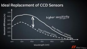
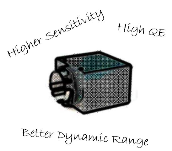
There are many advantages of CMOS versus CCDs machine vision cameras outlined below: 1 – Higher Sensitivity due to the latest pixel architecture which is beneficial in lower light applications. 2 – Lower dark noise will contribute to a higher fidelity image. 3 – Pixel well depth (saturation capacity) is improved providing higher dynamic range. 4 – Lower Power consumption. This becomes important as lower heat dissipation equals a cooler camera and less noise. 5 – Lower cost! – 5 Megapixel cameras used to cost ~ $2500 and only achieve 15 fps and now cost ~ $450 with increased frame rates. 6 – Smaller pixels reduce the sensor format decreasing the lens cost.
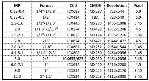
What CMOS image sensors cross over from existing CCD image sensors?
1st Vision’s sales engineers have over 100 years of combined experience to assist in your camera selection. With a large portfolio of lenses, cables, NIC card and industrial computers, we can provide a full vision solution!
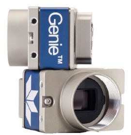
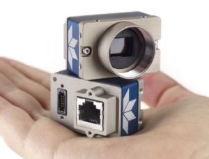
Teledyne Dalsa has released the latest addition to the Genie Nano family. Introducing the Nano M1950 and C1950 cameras using the Sony Pregius IMX392 image sensor. This is a great replacement for older Sony ICX818 CCD sensors.
These latest Nano models offer 2.4 MP (1936 x 1216) resolution with a GigE interface in color and monochrome with up to 102 frames per second utilizing TurboDrive.
What’s so interesting about the Nano M1950 and C1950 models?
2.4 MP resolution with the speed of the popular IMX174, but at the price of the IMX249:
Sony Pregius image sensors in a given resolution has created paired sensors, one being faster at a higher price and one slower at a lower price. The Nano M1940 / C1940 cameras use the IMX174 which is a great sensor and historically had the fastest speed at 2.4MP in GigE, but at a premium. We could opt for the Nano M1920 / C1920 cameras with the IMX249 at a lower price, but sacrificed speed.
Until now! – The latest Nano M1950 / C1950 models with the IMX392 provides the higher speed of the M1940 / C1940 cameras, but at the lower price of the Nano M1920 / C1920 cameras.
2.4MP resolution using a 1 /2 in sensor format, provides cost savings on lenses.
Thanks to the Sony Pregius Gen 2 pixel architecture, the pixel size is 3.45um, allowing the same resolution and eliminating the added cost of larger format lenses found in the IMX174 / IMX249 sensors which were 1 / 1.2″ formats.
When would you use the Sony Pregius IMX392 versus the IMX174 and IMX249 sensors?
The Sony Pregius IMX174 / IMX249 images still have an incredible dynamic range due to the pixel architecture found in the first generation image sensors. (Read more here on Gen 1 vs Gen 2). If you need dynamic range, with large well depths of 30Ke-, then use the IMX174 / IM249 sensors.
I’m so confused! Where can I get the specs on the new Nano M1950 / C1950, understand what sensors are in what cameras and get a quote?
The tough part today, is that there a ton of model #’s in the Sony Pregius sensors lineup and in turn camera product lines. Here’s a brief table to help with links to spec’s, related image sensors and a link to get a quote.
1st Vision’s sales engineers have over 100 years of combined experience to assist in your camera selection. With a large portfolio of lenses, cables, NIC card and industrial computers, we can provide a full vision solution!
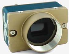
The first Genie Nano camera model with a quad-polarizer filter using the Sony Pregius IMX250-MZR 5.1MP monochrome image sensor is now available. The Teledyne Dalsa Nano M2450 cameraincorporates the nanowire polarizer filter allowing detection of both the angle and amount of polarized light.
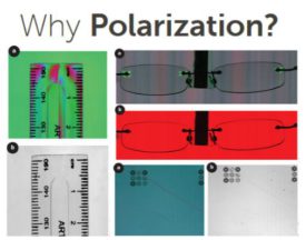
What problems can the Nano M2450 polarized camera solve?
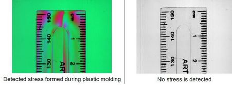
Polarized filtering can reduce the effects of reflections and glare from multiple directions and reveal otherwise undetectable features in the target scene. Polarization enables detection of stress, birefringence, through-reflection and glare from surfaces like glass, plastic, and metal. Sony’s newest image sensor, with its pixel-level polarizer structure, enables the detection of both the amount and angle of polarized light across a scene.
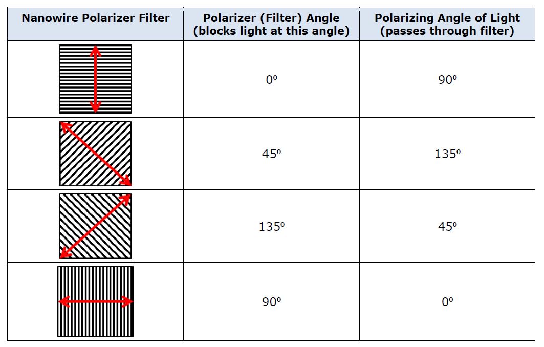
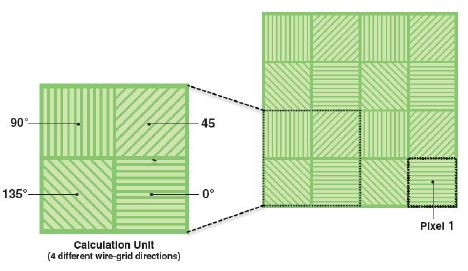
Four different angled polarizers (90°, 45°, 135° and 0°) are positioned on each pixel, and every block of four pixels comprises a calculation unit.
How does polarization work? Theory of operation
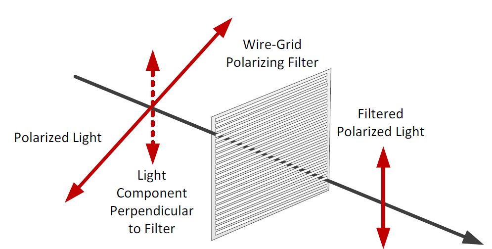
Polarization direction is defined as the electrical direction. Light, with its electrical field oscillating perpendicular to the nano wire grid, passes through the filter while that in the parallel direction is rejected.
For Polarized light, only the portion of the light vector perpendicular to the angle of the nanowire filter grid passes.
For example, with a wire-grid polarizer filter at 90 deg. to the maximum transmission is for polarized light at an angle of 0 deg.
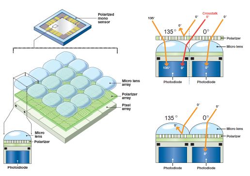
The polarizer filter is placed directly on the sensor’s pixel array, beneath the micro-lens array. This design, compared to polarize filters on top of the micro lens array reduced the possibility of light at a polarized angle being misdirected into adjacent pixels (cross talk) and incorrectly detected at the wrong angle.
The Genie Nano’s polarizer filter on the camera sensor is a 2 x 2 pattern, with each pixel having a nanowire polarizer filter with different angles (90, 45, 135 and 0 degree’s)
The image output pattern of the monochrome camera is arranged in 2 x 2 pixel block as follows:
That is, the first line output is an alternating sequence of pixels 0 & 35 degrees, with the following line of 45 and 90 degrees.
Given the proportion of light available through these four filters, any angle of polarized light can be calculated. Any given state of polarization can be composed by two linearly polarized waves in perpendicular directions. The state of polarization is determined by the relative amplitude and difference in phase between the two component waves.
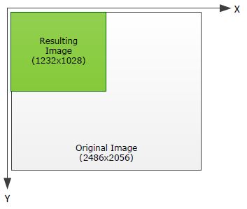
Calculations on the 2×2 filter blocks result in a single pixel for each polarizer filter angle, therefore the resulting image is one fourth the original image resolution. For example, with an original image of 2464×2056, the resulting image is 1232×1028 (original buffer width/2 and original buffer height/2) for a single polarizing angle.
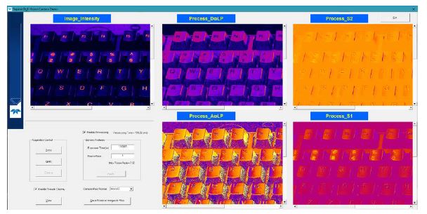
Teledyne Dalsa offers a Polarization demo user interface making it easy to test the polarization techniques for various applications. This includes the ability to see the results of various processing algorithms with the summed images.
As part of the demo program, images can be displayed with pseudo-color mapping
In summary, the new Dalsa Nano M2450 polarized camera can help resolve defects not detected by traditional imaging! Contact 1st Vision to arrange a camera demo in which we will provide the demo polarization software as well or discuss your application. Or click HERE to request a quote
1st Vision’s sales engineers have over 100 years of combined experience to assist in your camera selection. With a large portfolio of lenses, cables, NIC card and industrial computers, we can provide a full vision solution!
Our job as imaging specialists is to help our customers make the best decisions on which industrial camera and image sensor works best for their application. This is not a trivial task as there are many data points to consider, and in the end, a good image comparison test helps provide the true answer. In this blog post, we conduct another image sensor comparison for low light applications testing a long time favorite e2V EV76C661 Near Infra Red (NIR) sensor to the new Sony Starvis IMX178 and Sony Pregius IMX174 image sensor using IDS Imaging cameras.
An Industrial camera can be easily selected based on resolution and frame rates, but image sensor performance is more challenging. We can collect data points from the camera EMVA1288 test results and spectral response charts, but one can not conclude on what is best for the application based on one data point. In many cases, several data points need to be reviewed to start making an educated decision.
We started this review comparing 3 image sensors to determine which ones would perform best in low light applications.
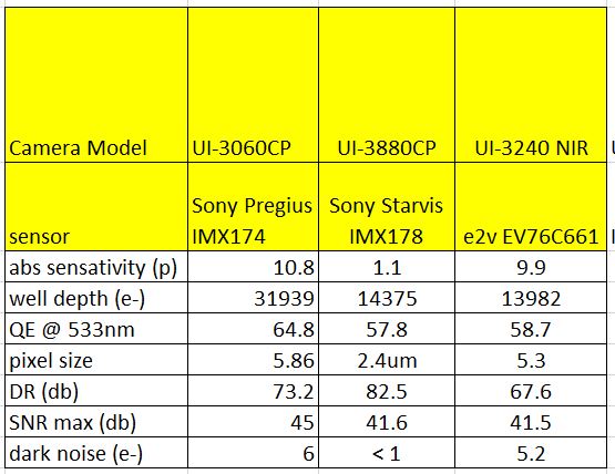
Below is a chart comparing the e2v EV76C661 NIR, Sony Starvis IMX178 and , Sony Pregius IMX174 image sensors found in the IDS Imaging UI-3240NIR,UI-3880CPand UI-3060CP cameras using EMVA1288 data to start. This provides us with accurate image sensor data to evaluate.
Table 1: Sensor comparison data
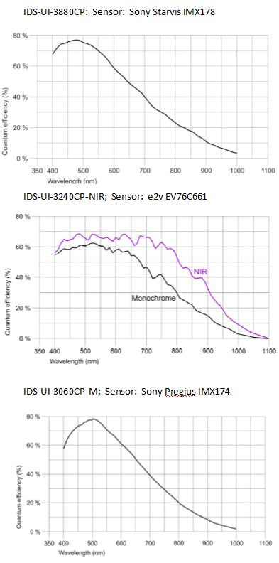
Camera Spectral Response curves
We also look at the Quantum Efficiency (QE) curves for the sensors to see the sensor performs over the light spectrum as seen to the left. (As a note, QE is the conversion of photon to an electrical charge (electrons)
For this comparison, our objective is to determine which sensor will perform best in low light applications with broadband light. From table 1, the IMX178 has very low absolute sensitivity (abs sensitivity) with taking ~ 1 photon to help make a adequate charge, however the pixels are small (2.4um), so maybe not gather light as well as larger pixels. It does have the best dark noise characteristics however. In comparison, the e2V sensor has 9.9 photons for abs sensitivity (not as good as 1 photon) and has a larger pixel size (bigger is better to collect light). The IMX174 proves to be interesting as well with the largest pixel of 5.86um and the highest QE @ 533nm.
Using the data from the spectral response curves however, helps give us more insight across the light spectrum. Given we are using a NIR enhanced camera, we will have significant more conversion of light to a create a charge on the sensor across most of the light spectrum. In turn, we expect we’d see brighter images from the e2V NIR IDS UI-3240 NIR camera.
As a note, one more data point is to look at the pixel well depth. Smaller pixels will saturate faster making the image brighter, so if other variables were close, this may also be taken into consideration.
As one can see, this is not trivial, but evaluating many of the data points, can give us some clues, but testing is really what it takes! So, lets now compare the images to see how they look.
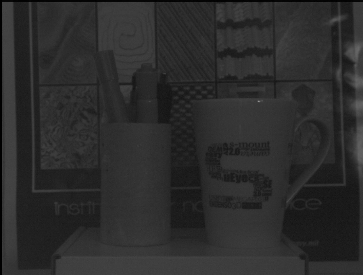
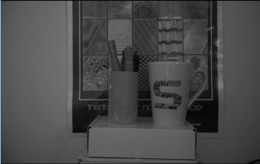
The following images were taken with the same exposure, lens + f-stop in the identical low light environment. In the 2nd image, the e2v image sensor in the IDS-UI-3240CP NIR provides the brighter image as some of the data points started to indicate. The IDS UI-3060CP-M (IMX174) is second best.
IDS UI-3880CP (IMX178)
IDS UI-3240CP NIR (e2v )
IDS UI-3060CP-M (Sony Pregius IMX174)
In low light situations, we can always add camera gain, but we pay the price of adding noise to the image. Depending on the camera image sensor, some have the ability to provide more gain than others. This is another factor to review when considering adding gain. We need to also take into account read noise as this will get amplified with gain. Our next part of our test is to turn up the gain to see how we compare.
The following set of images was taken again with the same lens + f-stop, lighting, but with gain at max for each camera.
IDS UI-3880CP with 14.5X gain
IDS UI-3240CP NIR with 4X gain
IDS UI-3060CP-M with 24X gain
The IDS-UI-3060CP-M has the highest gain available, but still keeps the read noise relatively low with 6 electrons. This in low light WITH gain, gives us a nice image in nearly dark environments.
Conclusion
We can review the data points until we are blue in the face and they can be very confusing. We can however take in all the data and help make some more educated decisions on which cameras to test. For example in the first test, we had a good idea the NIR sensor would perform well looking a the QE curves along with other data. In our second test, we may have seen the UI-3060CP had 24X gain vs others still with low read noise, giving an indication, we’d have relatively clean image.
In the end, 1st Vision’s sales engineers will help provide the needed information and help conduct testing for you! We spend a lot of time in our lab in order to provide first hand information to our customers!
Magnification of the images differs due to sensor size. Working distance of the cameras was kept identical in all setups and focused accordingly with distance.
This topic can be very complex! If we were to dig in even deeper, we’d take into consideration charge convergence of the pixel which effects sensitivity aside from looking at just QE!.. That’s probably another blog post!
As a reference, this image was taken with an Iphone and set to best represent what my eye viewed during our lab test. Note that the left container with markers was non-distinguishable to the human eye