Learn about CoaXpress and frame rates achievable with Allied Vision’s “Bonito Pro” cameras with CXP-6

Allied Vision Bonito Pro camera

What is  CoaXPress, especially with “CXP-6” capability?

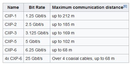
CoaXPress is an established industry standard allowing high speed communications over coaxial cable.  The current version supports bit rates up to 6.25 Gbits/sec over a single coaxial cable.  When used in parallel, two or more coaxial cables can provide incremental speed gains.  The naming convention associated with CoaXPress signify the bit rate as seen in the chart below.   In cases that you see CXP-6 has a bit rate of 6.25 Gb/s.  The 4 x means the number of lanes. Multiply the 2 and you get your total bit rate.

CXP CoaXpress

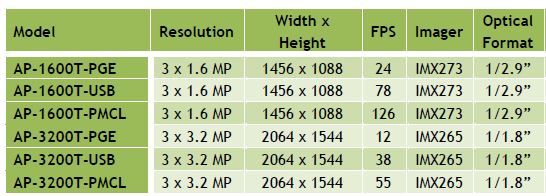
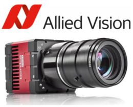
The new Allied Vision Bonito Pro cameras utilize 4 DIN 1.0/2.3 connectors on a CXP-6 interface (4 lanes) x 6.25Gbits/Sec. This  allows for resolutions of up to 26 megapixels to reach 70 frames per second (fps).  The first two Bonito PRO models (Bonito PRO X-2620 and X-1250) support high resolution with 26.6MP and 12.5MP at 80 and 142 fps respectively.

The Bonito PRO cameras are ideal for a wide range of applications including, 2D/ 3D surface inspection,  high speed printing, PCB & Electronics inspection.

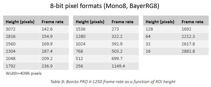
Even faster frame rates can be achieved using the Bonito Pro X1250 (12.5MP) in partial scan mode.  Set to a 768 line height, a rate of 503 fps can be achieved!

Bonito Pro frame rates

The following video’s are good representations of what this relates to in real applications which you can appreciate.

Full specifications for the Allied Vision Bonito Pro cameras can be found HERE, but main features and benefits include:

  • Sensors available in Monochrome (X-1250B) and Color (X-1250C) and extended near-infrared (X1250B NIR ) models
  • On board defect pixel and 2D fixed pattern noise correction for improved image quality
  • Fan-less design for industrial imaging applications.
  • DIN 1.0 / 2.3 CoaXPress connections for secure operation in industrial environments.
  • Single cable solutions using trigger and power over CoaXPress (PoCXP)

contact us1st Vision’s sales engineers have over 100 years of combined experience to assist in your camera selection.  With a large portfolio of lenses, cables, NIC card and industrial computers, we can provide a full vision solution!


UPDATE:  New video of the Bonito Pro detailing the multi-ROI function


Dalsa Nano M2450 polarized camera: Resolving defects that are undetectable with traditional imaging!

Dalsa Polarization camera

Genie Nano cameraThe first Genie Nano camera model with a quad-polarizer filter using the Sony Pregius IMX250-MZR 5.1MP monochrome image sensor is now available.  The Teledyne Dalsa Nano M2450 camera incorporates the nanowire polarizer filter allowing detection of both the angle and amount of polarized light.

What problems can the Nano M2450 polarized camera solve?

Polarized filtering can reduce the effects of reflections and glare from multiple directions and reveal otherwise undetectable features in the target scene.  Polarization enables detection of stress, birefringence, through-reflection and glare from surfaces like glass, plastic, and metal.  Sony’s newest image sensor, with its pixel-level polarizer structure, enables the detection of both the amount and angle of polarized light across a scene. Dalsa Nano polarization camera


Four different angled polarizers (90°, 45°, 135° and 0°) are positioned on each pixel, and every block of four pixels comprises a calculation unit.Contact 1st vision for pricing

How does polarization work?  Theory of operation

Polarization direction is defined as the electrical direction.  Light, with its electrical field oscillating perpendicular to the nano wire grid, passes through the filter while that in the parallel direction is rejected.

For Polarized light, only the portion of the light vector perpendicular to the angle of the nanowire filter grid passes.

polarization filter

For example, with a wire-grid polarizer filter at 90 deg. to the maximum transmission is for polarized light at an angle of 0 deg.

polarizer filterThe polarizer filter is placed directly on the sensor’s pixel array, beneath the micro-lens array.  This design, compared to polarize filters on top of the micro lens array reduced the possibility of light at a polarized angle being misdirected into adjacent pixels (cross talk) and incorrectly detected at the wrong angle.

Dalsa polarizer filter theory

The Genie Nano’s polarizer filter on the camera sensor is a 2 x 2 pattern, with each pixel having a nanowire polarizer filter with different angles (90, 45, 135 and 0 degree’s)

The image output pattern of the monochrome camera is arranged in 2 x 2 pixel block as follows:

Pixel blocks


That is, the first line output is an alternating sequence of pixels 0 & 35 degrees, with the following line of 45 and 90 degrees.

Given the proportion of light available through these four filters, any angle of polarized light can be calculated. Any given state of polarization can be composed by two linearly polarized waves in perpendicular directions. The state of polarization is determined by the relative amplitude and difference in phase between the two component waves.

Calculations on the 2×2 filter blocks result in a single pixel for each polarizer filter angle, therefore the resulting image is one fourth the original image resolution. For example, with an original image of 2464×2056, the resulting image is 1232×1028 (original buffer width/2 and original buffer height/2) for a single polarizing angle.

resulting image

Teledyne Dalsa offers a Polarization demo user interface making it easy to test the polarization techniques for various applications.  This includes the ability to see the results of various processing algorithms with the summed images.

Dalsa Polarization demo
As part of the demo program, images can be displayed with pseudo-color mapping

In summary, the new Dalsa Nano M2450 polarized camera can help resolve defects not detected by traditional imaging!   Contact 1st Vision to arrange a camera demo in which we will provide the demo polarization software as well or discuss your application.  Or click HERE to request a quoteContact us


Need line scan?  – With the addition of the Genie Nano polarized model, Teledyne DALSA is the first company to offer polarization for both area and line scan (Piranha™4 polarization) cameras

1st Vision’s sales engineers have over 100 years of combined experience to assist in your camera selection.  With a large portfolio of lenses, cables, NIC card and industrial computers, we can provide a full vision solution!

Related Posts

Dalsa line scan polarization camera makes invisible visible!

Teledyne Dalsa TurboDrive 2.0 breaks past GigE limits now with 6 levels of compression

CCD vs CMOS industrial cameras – Learn how CMOS image sensors excel over CCD!

CCD vs CMOSCMOS Image sensors used in machine vision industrial cameras are now the image sensor of choice!  But why is this?

Allied Vision conducted a nice comparison between CCD and CMOS cameras showing the advantages in the latest Manta cameras.

Until recently, CCD was generally recommended for better image quality with the following properties:

  • High pixel homogeneity, low fixed pattern noise (FPN)
  • Global shutters for machine vision applications requiring very short exposure times

Where in the past, CMOS image sensors were used due to existing advantages:

  • High frame rate and less power consumption
  • No blooming or smear image artifacts contrary to CCD image sensors
  • High Dynamic Range (HDR) modes for acquisition of contrast rich and extremely bright objects.

Today CMOS image sensors offer many more advantages in industrial cameras versus CCD image sensors as detailed below

Overall key advantages are better image quality than earlier CMOS sensors due to higher sensitivity,  lower dark noise, spatial noise and higher quantum efficiency (QE) as seen in the specifications comparing a CCD and CMOS camera.

CCD vs CMOS comparisonsSony ICX655 CCD vs a Sony IMX264 CMOS sensor

Comparing the specifications between CCD and CMOS  industrial cameras, the advantages are clear.

  • Higher Quantum Efficiency (QE) – 64% vs 49% where higher is better in converting photons to electrons. 
  • Pixel well depth (ue.sat: ) – 10613 electrons (e-) vs 6600 e- where a higher well depth is beneficial
  • Dynamic range (DYN) – Where CMOS provides almost +17 dB more dynamic range.  This is a partial result of the pixel well depth along with low noise.
  • Dark Noise:  CMOS is significantly less vs CCD with only 2 electrons vs 12!

Images are always worth a thousand words!  Below are several comparison images contrasting the latest Allied Vision CMOS industrial cameras vs CCD industrial cameras.

Dynamic Range of today’s CMOS image sensors are contributed to several of the characteristics above and can provide higher fidelity images with better dynamic range and lower dark noise as seen in this image comparison of a couple of electronics parts

Allied vision cmos vs ccdThe comparison above illustrates how higher contrast can be achieved with high dynamic range and low noise in the latest CMOS industrial cameras

  • High noise in the CCD image causes low contrast between characters on the integrated circuit, whereas the CMOS sensor provides higher contrast.
  • Increased Dynamic range from the CMOS image allows darker and brighter areas in an image to be seen.  The battery (left part) is not as saturated vs the CCD image allowing more detail to be observed.

Current CMOS image sensors eliminate several artifacts and provide more useful images for processing.  The images below are an example of a PCB with LEDs illuminated imaged with a CCD vs CMOS industrial camera

ccd vs cmos artifactsCMOS images will result in less blooming of bright areas (LED’s for example in the image), smearing (vertical lines seen in the CCD image) and lower noise (as seen in the darker areas, providing higher overall contrast)

  • Smearing (vertical lines seen in the CCD image) are eliminated with CMOS.  Smear has inherently been a bad artifact of CCDs.
  • Dynamic Range inherent to CMOS sensors allow the LED’s to not saturates as much as the CCD allowing more detail to be seen.
  • Lower noise in the CMOS image, as seen in the bottom line graph shows a cleaner image.

More advantages of new CMOS image sensors include:

  • Higher frame rates and shutter speeds over CCD resulting in less image blur in fast moving objects.
  • Much lower cost of CMOS sensors translate into much lower cost cameras!
  • Improved global shutter efficiency.

CMOS image sensor manufacturers are also working to design sensors that easily replace CCD sensors making for an easy transition which results in lower cost and better performance.  Allied Vision has several new cameras replacing current CCD’s with more to come!  Below are a few popular cameras / image sensors that have been recently crossed over to CMOS image sensors

Sony ICX424 and Sony ICX445 (1/3″ sensor)  found in the Manta G-032 and Manta G-125 cameras are now replaced by the Sony IMX273 in the Manta G-158 camera keeping the same sensors size.  (Read more here)

Sony ICX424 (1/3″sensor), can also be replaced by the Sony IMX287 (1/2.9″ sensor) with pixel sizes of 6.9um closely matching the older IMX424 having 7.4um pixels.  Allied Vision Manta G-040 is a nice solution with all the benefits of the latest CMOS image sensor technology.  View the short videos below for the highlights.


Contact us


Related Posts

What are the attributes to consider when selecting a camera and its performance?

Allied Vision Manta G-040 & G-158 provide great replacements to legacy CCD cameras

Upgrade your 5MP CCD (Sony ICX625) camera for higher performance with an Allied Vision Mako G-507 (IMX264)


3-CMOS machine vision cameras bring color fidelity to the market at half the price as previous models

JAI- 3CMOS Apex cameras

JAI Apex Series cameras

Single sensor machine vision cameras use a mosaic filter placed on the sensor to create color images.  This is also called a ‘Bayer’ filter, named after the person who invented it.  However, color images from this filter lose resolution and color fidelity compared to ‘true’ color images.  Spatial resolution is lost due to interpolation, while the Bayer filter pattern reduces true color representation, sensitivity and dynamic range.   To overcome these issues, multi-sensor (3-CCD / 3-CMOS)  machine vision cameras can be used.

Typically, machine vision 3-CCD cameras were high cost, until now with CMOS sensors becoming the leading image sensor technology.  Now, machine vision 3-CMOS machine cameras provide major benefits over Bayer cameras and at more attractive entrance cost.

CMOS sensor technology has lowered the price of 3 image sensor cameras by 50% providing a better alternative to Bayer color cameras for many applicationsJAI’s Apex Series 3-CMOS cameras are the game changer for demanding color applications.    Contact us

Watch this video to learn more about 3-CCD/3-CMOS cameras

Machine Vision 3-CMOS cameras Vs Bayer cameras provide major benefits for color applications

Better color precision – Accurate RGB values are obtained for each pixel so there is no interpolation/estimation of colors as found in Bayer cameras. This can be critical for paint/ink matching, printing inspection systems, digital pathology, or other applications where color values must be extremely accurate.comparison images

Better spatial resolution –  The Bayer interpolation process also tends to blend edges and small details. While this can be pleasing to the eye, it can make spatial measurements or bar code reading imprecise or error prone, causing the use of more expensive high resolution Bayer cameras or requiring a second monochrome camera for imaging these details

JAI Apex 3-CMOSJAI 5MP Bayer image

Higher sensitivity – The prism glass in the AP-3200T-USB and associated cameras, has better light transmission properties than the polymer filters in a standard Bayer sensor.  This enables more light to reach the pixels for better overall sensitivity and lower lighting requirements.

Lower noise, higher dynamic range – White balancing on a JAI prism camera can be done on individual channels with shutter adjustments instead of adding gain to the image. This results in lower noise and higher usable dynamic range.

3ccd vs Bayer dynamic range

What about “improved” Bayer capabilities like 5×5 interpolation?

Several camera manufacturers claim vastly improved capabilities for color imaging, including 5×5 de-Bayering, color-anti-aliasing, denoising
and improved sharpness.  But consider the following:  5×5 interpolation
means you are using an even larger area within the image to estimate each pixel’s color value. So while this can do a better job of “smoothing” color transitions to the eye, it can actually result in less-precise color values for image processing, especially where color variation is high.

This is illustrated in the following images, under identical conditions, by a camera with 5 x 5 debayering and a JAI Apex 3-CMOS camera.  The CIE L*a*b* reference chart provides a set of exact color values when expected under specified lighting conditions.   The result:  5×5 debayering results in 40%  out of match to the expected colors vs 13% for the JAI Apex 3-CMOS camera!

JAI 3-CMOS Apex camera matchingMore advanced color imaging features

JAI’s Apex 3-CMOS machine vision cameras provide additional advanced features aside from excellent color fidelity and highlighted as follows:

  • Color Space conversion:  Color data from the camera can be provided using built in conversions to several color spaces including sRGB, Adobe RGB, CIE XYZ and HSI.  Custom RGB conversions can also be done using the cameras color matrix circuit.
  • Color Enhancer Function:  Allows the 3-CMOS cameras to “boost” the intensity of 6 colors to help features stand out, such as the red color of blood vs surrounding tissue in a medical application.  Additionally, degree’s of edge enhancement can be to increase the contrast of color boundaries.  JAI 3-CMOS Color enhancement
  • Color Binning:  While most Bayer cameras do not offer this, due to the prism architecture of the 3-CMOS cameras, you can easily bin pixels by 1×2, 2×1 and 2×2 to increase sensitivity, reduce shot noise and / or increase the frame rate.
  • Color temperature presets from 3200K, 5000K, 6500K and 7000K

All of these features, along with reduced costs for 3-CMOS color cameras, now make this a very attractive solution for demanding color applications!  Applications in eye diagnostics, pathology, surgical imaging, meat/food inspection, print inspection and automotive color matching are a few that would highly benefit from the JAI Apex 3-CMOS camera series.

Contact us

Need to proof 3-CMOS / 3-CCD prism based cameras will enhance your application?  Let’s discuss sending you a demo camera!

Currently there are 6 new CMOS models outlined below and full specifications can be found HERE.   

JAI Apex Series cameras

1st Vision is the leading provider of industrial imaging components with over 100 years of combined imaging experience.   Do not hesitate to contact us regarding the new prices of the 3-CMOS cameras!

Be sure to visit our related blogs on 3-CCD and Prism based cameras

How does a 3CCD camera improve color accuracy and spatial resolution versus standard Bayer color cameras?

White Paper – Learn about High Dynamic Range (HDR) Imaging techniques for Machine Vision

White Paper -How does prism technology help to achieve superior color image quality?