What is the fastest 2.4MP GigE camera at the lowest price point? Dalsa’s new Nano M1950 / C1950!

Dalsa Nano

Dalsa Nano
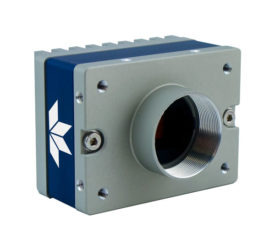
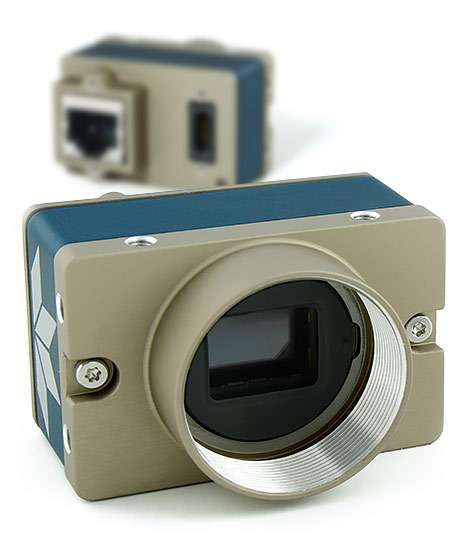
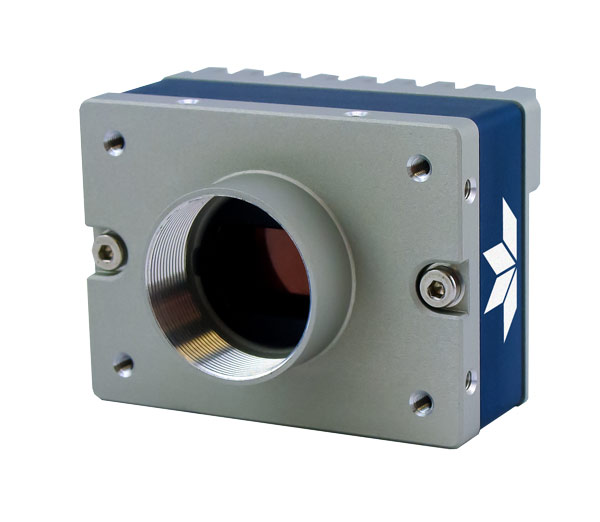
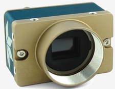
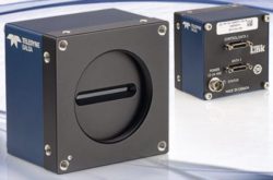
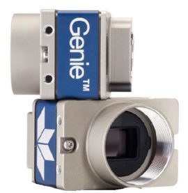
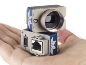
Teledyne Dalsa has released the latest addition to the Genie Nano family.  Introducing the Nano M1950 and C1950 cameras using the Sony Pregius IMX392 image sensor.  This is a great replacement for older Sony ICX818 CCD sensors.

These latest Nano models offer 2.4 MP (1936 x 1216) resolution with a GigE interface in color and monochrome with up to 102 frames per second utilizing TurboDrive.

What’s so interesting about the Nano M1950 and C1950 models?

2.4 MP resolution with the speed of the popular IMX174, but at the price of the IMX249:  
Sony Pregius image sensors in a given resolution has created paired sensors, one being faster at a higher price and one slower at a lower price.  The Nano M1940 / C1940 cameras use the IMX174 which is a great sensor and historically had the fastest speed at 2.4MP in GigE, but at a premium.  We could opt for the Nano M1920 / C1920 cameras with the IMX249 at a lower price, but sacrificed speed.

Until now! – The latest Nano M1950 / C1950 models with the IMX392 provides the higher speed of the M1940 / C1940 cameras, but at the lower price of the Nano M1920 / C1920 cameras. 

2.4MP resolution using a 1 /2 in sensor format, provides cost savings on lenses.
Thanks to the Sony Pregius Gen 2 pixel architecture, the pixel size is 3.45um, allowing the same resolution and eliminating the added cost of larger format lenses found in the IMX174 / IMX249 sensors which were 1 / 1.2″ formats.

Contact 1stVision to get our recommendations on lens series designed for the 3.45um pixel pitch. 

When would you use the Sony Pregius IMX392 versus the IMX174 and IMX249 sensors? 

The Sony Pregius IMX174 / IMX249 images still have an incredible dynamic range due to the pixel architecture found in the first generation image sensors.  (Read more here on Gen 1 vs Gen 2).  If you need dynamic range, with large well depths of 30Ke-, then use the IMX174 / IM249 sensors.

I’m so confused!   Where can I get the specs on the new Nano M1950 / C1950, understand what sensors are in what cameras and get a quote?

The tough part today, is that there a ton of model #’s in the Sony Pregius sensors lineup and in turn camera product lines.  Here’s a brief table to help with links to spec’s, related image sensors and a link to get a quote.

Sensor          Model 
IMX174         Nano M1940 / C1940          GET QUOTE
IMX249        Nano M1920 / C1920           GET QUOTE
IMX392        Nano M1950 / C1950           GET QUOTE

1st Vision’s sales engineers have over 100 years of combined experience to assist in your camera selection.  With a large portfolio of lenses, cables, NIC card and industrial computers, we can provide a full vision solution!

Contact us to help in the specification and providing pricing

Ph:  978-474-0044  /  info@1stvision.com  / www.1stvision.com

Related Blogs & Technical resources

Imaging Quick ref Poster
Quick Reference Imaging poster download

https://www.1stvision.com/machine-vision-solutions/2019/04/sony-pregius-3rd-generation-image-sensor.html

Teledyne Dalsa TurboDrive 2.0 breaks past GigE limits now with 6 levels of compression

What is a lens optical format? Can I use any machine vision camera with any format? NOT!

Learn about the new 5GigE camera interface

Dalsa Nano 5GigE

Machine vision interfaces have continued to evolve over the years increasing data throughput and cable lengths.  Commonly used interfaces are GigE and USB3.  However, 5GigE is an interface now gaining attention in the industrial imaging / machine vision market with some nice advantages.

We will outline the benefits of 5GigE, but first, lets give a brief overview of the commonly used camera interfaces, with their pluses and minuses:

GigE  / GigE Vision

  • 110 MB/s of sustainable throughput.  In real world terms, a HD, 2MP camera can get 50-55 fps in 8 bit mono or 8 bit color mode.  Note, this isn’t real HD, since you need 60 FPS.
  • Data cable lengths up to 100m using regular CAT 5e/6 cable.
  • Easy to put multiple cameras on a system.

USB 3 / USB3 Vision

  • 420 MB/s of data throughput.    A HD 2MP camera can run 60 fps in 8 bit mono or color and can  also run RGB at 60 FPS no problem.  With the higher throughput,  a 5MP camera can achieve 85 fps in 8 bit mode.
  • Data cables up to 5 meters and up to 20 meters with active cables. However, active cables can be quite costly, adding up to $200 in cost.
  • Not as easy as GigE to put multiple cameras on a system, and gets harder with each additional camera, especially if you have limited USB3 controllers.

As a note, there is no cost difference when using cameras with the same sensor from the same manufacturer with USB or GigE!  They will cost about the same with no premium for one interface over the other.

gige nano 5gigeWhat are the limitations of GigE and USB3 now solved by 5GigE?

  • USB3 is limited in cable length, so going faster than GigE is great, but you can not have long cable lengths.
  • GigE has cable lengths up to 100 meters, but is limited to ~ 110MB/s of data, so you do not have the high frame rates as in a USB3 camera.
  • USB3 in 4+ camera systems is not as stable as GigE AND you’re still limited on cable lengths.

Wait! – What about 10GigE? 

Up until now, 10G was the next interface. However, the jump to 10G has quite a few limitations as outlined below.

  • Heat generation is significant, so cameras are large and not in the smaller 29 x 29mm cube form factor.
  • Not a lot of demand for very high speed 10G, so not a lot of sensors being offered
  • Minimal number of manufacturers for 10G, higher cost.
  • Special cabling, either optical or high quality cat 7.

What we have found is that there are several types of applications for 10G cameras and are as follows

  • Applications where you need 10G of speed of course (high resolution + fast frame rates)
  • Require greater than  110MB/s of data and need long cable lengths.
  • Where there is the required combination of 110MB/s for high frame rates, multiple cameras and long cable lengths, 10G is a perfect solution.

We have seen that the need for higher bandwidth + long cable lengths is more prominent vs. the real need for 10GigE!

 Introducing 5GigE that provides increased bandwidth, long cable lengths at reasonable prices! or N Base T.5GigE machine vision applications

5GigE (also known as N Base T) has become a new standard for industrial, machine vision cameras.

In the general compute world, a much much larger market than vision, there has also been a need to go faster than GigE. However, the issue of replacing the existing cabling is the major issue preventing this. If you think of a big box store, say a Home Depot for instance, the amount of cabling is huge. Ripping that out and rewiring far exceeds the cost of the equipment to use it!

5G was made to go faster, but use existing cabling. Regular cat6e cable can be used, and 5G is a subset of 10G, so all switches etc. can be kept in service.

5G gives users in the vision market USB3 speeds, but with ALL of the regular GigE features, at a very small premium!

get quote1st Vision’s sales engineers have over 100 years of combined experience to assist in your camera selection.  With a large portfolio of lenses, cables, NIC card and industrial computers, we can provide a full vision solution!


Dalsa Nano M2450 polarized camera: Resolving defects that are undetectable with traditional imaging!

Dalsa Polarization camera

Genie Nano cameraThe first Genie Nano camera model with a quad-polarizer filter using the Sony Pregius IMX250-MZR 5.1MP monochrome image sensor is now available.  The Teledyne Dalsa Nano M2450 camera incorporates the nanowire polarizer filter allowing detection of both the angle and amount of polarized light.

What problems can the Nano M2450 polarized camera solve?

Polarized filtering can reduce the effects of reflections and glare from multiple directions and reveal otherwise undetectable features in the target scene.  Polarization enables detection of stress, birefringence, through-reflection and glare from surfaces like glass, plastic, and metal.  Sony’s newest image sensor, with its pixel-level polarizer structure, enables the detection of both the amount and angle of polarized light across a scene. Dalsa Nano polarization camera


Four different angled polarizers (90°, 45°, 135° and 0°) are positioned on each pixel, and every block of four pixels comprises a calculation unit.Contact 1st vision for pricing

How does polarization work?  Theory of operation

Polarization direction is defined as the electrical direction.  Light, with its electrical field oscillating perpendicular to the nano wire grid, passes through the filter while that in the parallel direction is rejected.

For Polarized light, only the portion of the light vector perpendicular to the angle of the nanowire filter grid passes.

polarization filter

For example, with a wire-grid polarizer filter at 90 deg. to the maximum transmission is for polarized light at an angle of 0 deg.

polarizer filterThe polarizer filter is placed directly on the sensor’s pixel array, beneath the micro-lens array.  This design, compared to polarize filters on top of the micro lens array reduced the possibility of light at a polarized angle being misdirected into adjacent pixels (cross talk) and incorrectly detected at the wrong angle.

Dalsa polarizer filter theory

The Genie Nano’s polarizer filter on the camera sensor is a 2 x 2 pattern, with each pixel having a nanowire polarizer filter with different angles (90, 45, 135 and 0 degree’s)

The image output pattern of the monochrome camera is arranged in 2 x 2 pixel block as follows:

Pixel blocks


That is, the first line output is an alternating sequence of pixels 0 & 35 degrees, with the following line of 45 and 90 degrees.

Given the proportion of light available through these four filters, any angle of polarized light can be calculated. Any given state of polarization can be composed by two linearly polarized waves in perpendicular directions. The state of polarization is determined by the relative amplitude and difference in phase between the two component waves.

Calculations on the 2×2 filter blocks result in a single pixel for each polarizer filter angle, therefore the resulting image is one fourth the original image resolution. For example, with an original image of 2464×2056, the resulting image is 1232×1028 (original buffer width/2 and original buffer height/2) for a single polarizing angle.

resulting image

Teledyne Dalsa offers a Polarization demo user interface making it easy to test the polarization techniques for various applications.  This includes the ability to see the results of various processing algorithms with the summed images.

Dalsa Polarization demo
As part of the demo program, images can be displayed with pseudo-color mapping

In summary, the new Dalsa Nano M2450 polarized camera can help resolve defects not detected by traditional imaging!   Contact 1st Vision to arrange a camera demo in which we will provide the demo polarization software as well or discuss your application.  Or click HERE to request a quoteContact us


Need line scan?  – With the addition of the Genie Nano polarized model, Teledyne DALSA is the first company to offer polarization for both area and line scan (Piranha™4 polarization) cameras

1st Vision’s sales engineers have over 100 years of combined experience to assist in your camera selection.  With a large portfolio of lenses, cables, NIC card and industrial computers, we can provide a full vision solution!

Related Posts

Dalsa line scan polarization camera makes invisible visible!

Teledyne Dalsa TurboDrive 2.0 breaks past GigE limits now with 6 levels of compression

Dalsa line scan polarization camera makes invisible visible!

Teledyne Dalsa has released the first line scan polarization camera for machine vision.  The Piranha4 polarization camera provides the capability of detecting , stress, surface roughness,  birefringence and physical properties undetectable with conventional imaging making the invisible visible!

This unique technique uses four polarization channels with a color line scan camera solving various applications, but not limited to the following:

Glass Inspection:  Glass bottles, architectural glass sheets, and automobile windshields, etc. – Enables inspection of internal stress and defects non-visible with conventional imaging

Dalsa Polorized ruler

Film inspection: transparent films, packaging films, and patterned films etc. – Detect scratches, digs, and other surface defects that are difficult to detect with conventional imaging   Dalsa Polarized scratch

Precision optics: optical lens, prisms, fibers, and micro-optical – Detect residual internal stress and thermal annealing effects
polarized - stress in sun glasses

Flat Panel Display and PCB inspection: Thin film transistors, organic LEDs, printed circuit boards etc.- inspect ITO, dust particles, films thickness, and surface defects with enhanced contrast

Carbon fibers: effectively inspect the quality of composite materials that are widely used in aircraft, aerospace, wind energy, and automotive industry

Food and material sorting: Increase sorting accuracy and detecting capability of foreign materials such as plastics, glasses, metals etc. with polarization imaging

Bio-medicine: digital pathology, in vitro cells culture, optical coherence tomography etc.- Provides additional information in birefringence tissues
Remote sensing: helps identifying special objects from natural background
And many more…

Contact 1st vision

Line scan polarization camera Features

  • CMOS Quadlinear sensor  – 2048 pixels
  • High speed line rate of 70k hz with 14.08 um pixels
  • Camera Link interface
  • Three polarization states plus and unfiltered channel (Output format with 0 deg (S component), 90 deg (P component), 135 deg and unfiltered polarization states.)

Full specifications on the Teledyne Dalsa polarization camera ( P4-CP-02K07Q-00-R ) can be found HERE

line scan camera Polarization angles

White Paper  – Learn about this unique polarization technique with line scan cameras!   This white paper covers the following topics

  • How polarization techniques work in transmission and reflectance configuration
  • Comparison of three polarization filter technologies
  • How the sensor architecture is configured for polarization effects and visualization of defects.

line scan polarization camera white paper

1stVision has a strong working knowledge of polarization techniques, line scan cameras and lighting and can discuss your application in detail.

Contact us to talk to an expert!

Related Blog posts:
Teledyne Dalsa release of low cost GigE and camera link color line scan cameras

Video Tutorial:  How to setup HDR Imaging in Teledyne Dalsa Linea Line scan cameras