Derived from 10 Gigabit Ethernet, and adapted to GigE Vision standards, Teledyne DALSA has continued buildout of the Nano series from 1GigE, 2GigE, 5GigE, and now 10GigE.
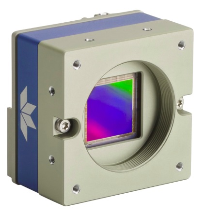
The Genie Nano series is now extended from 1, 2.5 and 5GigE with new 10GigE camera models M/C8200 and M/C6200. These are based on Teledyne e2v’s 67Mp and 37Mp monochrome and color sensors. These high resolution sensors generate a lot of image data to transfer to the host computer, but at 10GigE speeds they achieve frame rates to:
15fps – for the 67Mp cameras
20fps – for the 37Mp cameras
There are four new models offered, in color and monochrome versions for each sensor variant. All are GenICam, GigE Vision 2.0 compliant. They are multi ROI with up to 16 x Region of Interest (ROI). The cameras have all-metal bodies and 3 year warranties.
Further, the M/C8200, at 59 mm x 59 mm, is the industry’s smallest 67M 10GigE Vision camera, for those needing high-resolution and high-performance in a comparatively small form factor.
These 10GigE models share all the other features of the Teledyne DALSA Genie Nano Series, for ease of integration or upgrades. Such features include but are not limited to:
Power over Ethernet (PoE) – single cable solution for power, data, and control
Precision Time Protocol (PTP) synchronization of two or more cameras over GigE network, avoiding the need for hardware triggers and controllers
Verify critical imaging events such as lost frames, lines, or triggers
Tag images for traceability
Trigger to Image Reliability (T2IR) – courtesy Teledyne DALSA
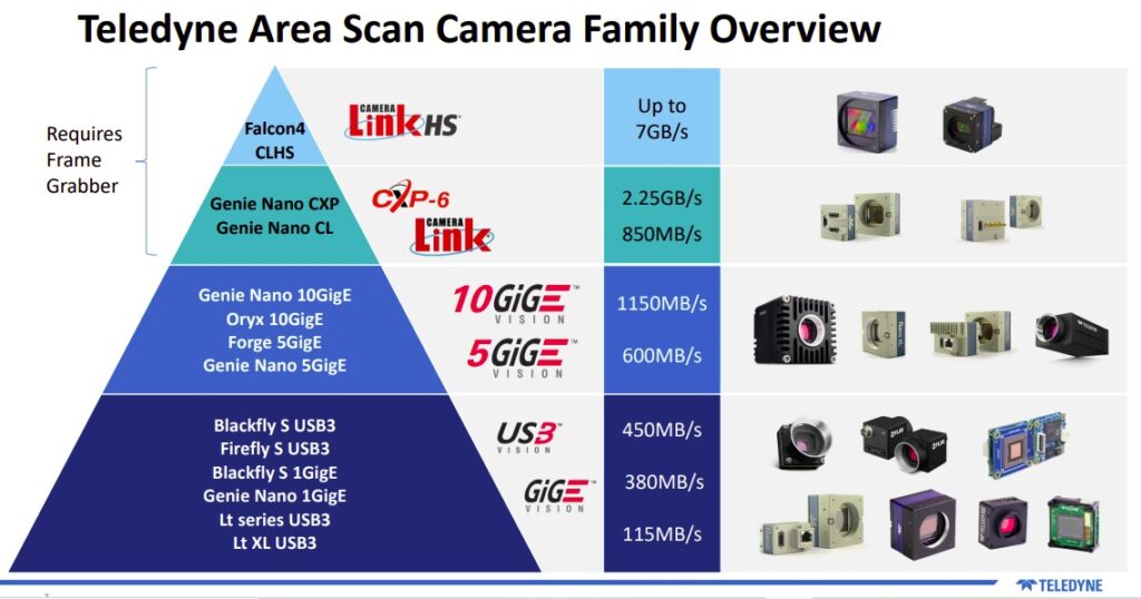
Across the wide range of Teledyne DALSA (area scan) cameras shown below, the Genie Nano 10GigE cameras are at the upper end of the already high-performance mid-range.
Genie Nano 10GigE area scan cameras in the Teledyne portfolio – courtesy Teledyne DALSA
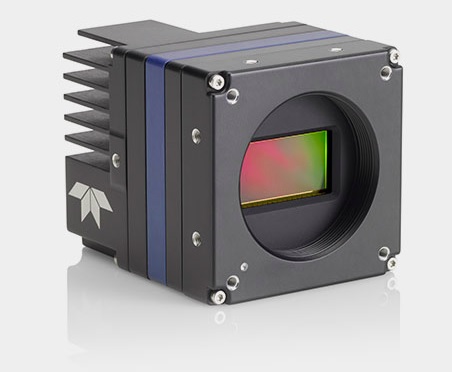
Who needs another 2.8Mpix camera? In this case it’s not about the pixel count per se, but about the frame rates and the dynamic range.
Falcon™4-CLHS – courtesy Teledyne DALSA
With more common interfaces like GigE and 5GigE we expect frame rates from a 2.8 Mpix camera in the range 20 – 120fps, respectively. But with the Camera Link High Speed (CLHS) interface, Teledyne DALSA’s new Falcon4-M2240 camera can deliver up to 1200fps. If your application demands high-speed performance together with 2.8Mpix resolution, this camera delivers.
Besides speed, an even more remarkable feature of the Falcon4-M2240, based on the Teledyne e2v Lince 2.8 MP, is a pixel well depth, or full well capacity, of ~138 [ke-]. THAT VALUE IS NOT A TYPO!! It really is ~138 [ke-]. Other sensors also thought of as high quality offer pixel well depths only 1/10th of this value, so this sensor is a game changer.
Why does pixel well depth matter? Recall the analogy of photons to raindrops, and pixel wells to buckets. With no raindrops, the bucket is empty, just as with no photons quantized to electrons, the pixel well is empty and the monochrome pixel would correspond to 0 or full-black. When the bucket, or pixel well, becomes exactly full with the last raindrop (electron) it can hold, it’s reached it’s full well capacity – the pixel value would be fully saturated at white (for a monochrome sensor).
The expressive capacity of each pixel admits the widest range of values in correlation to the full well capacity before charge overflows, so the camera is calibrated by the designer according to the sensor’s capabilities. Sensors with higher full well capacity are desirable, since they can capture all the nuances of the imaging target, which in turn gives your software maximum image features to identify.
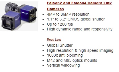
This newest member of the Falcon4 family joins siblings with sensors offering 11, 37, and 67 Mpix respectively. The Falcon4 family represents continues the success of the Falcon2 family, all of which share many common features: These include:
CMOS global shutter
High dynamic range
1000x anti-blooming
M42 to M95 optics mount
Camera Link or Camera Link HS interface
Falcon family members share many features
Even before the new firmware update (V1.02), Falcon4 cameras already offered:
Now with Firmware 1.02 the Falcon4 family gets these additional features:
Multi-ROI
ROI position change by sequencer cycling
Digital gain change by sequencer cycling sequencer cycling of Digital Gain
Exposure change by sequencer cycling
Sequencer cycling of output pulse
Meta Data
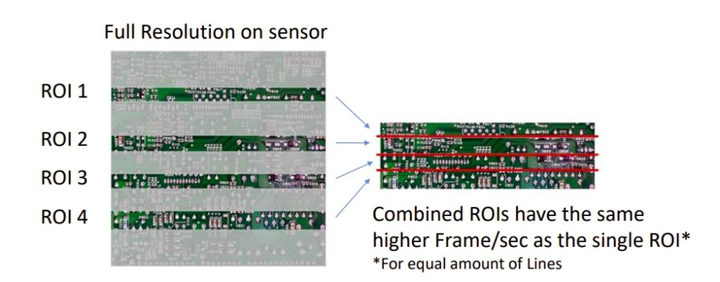
Multi-ROI
Higher FPS by sending only ROIs needed – courtesy Teledyne DALSA
Region Of Interest (ROI) capabilities are compelling when an application has defined regions within a larger field that can be read out, skipping the un-necessary regions, thereby achieving much higher framerates than having to transfer the full resolution image from camera to host. It’s like having a number of smaller-sensor cameras, each pointed at their own region, but without the complexity of having to manage multiple cameras. As shown in the image below, the composite image frame rates are equivalent to the single ROI speed gains one might have known on other cameras.
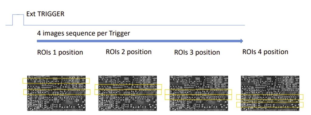
Sequencer cycling of ROI position:
Each trigger changes ROI position – courtesy Teledyne DALSA
Cycling the ROI position for successive images might not seem to have obvious benefits – but what if the host computer could process image 1, while the camera acquires and begins transmitting image 2, and so forth? Overall throughput for the system rises – efficiency gains!
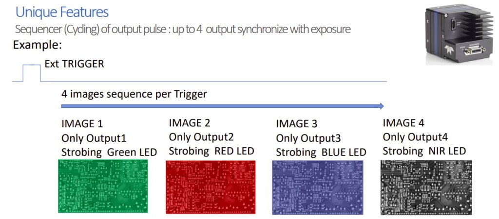
Sequencer cycling of output pulse:
Courtesy Teledyne DALSA
For certain applications, it can be essential to take 2 or more exposures of the same field of view, each under different lighting conditions. Under natural light, one might take a short, medium, and long exposure duration, to hedge on which is best, let the camera or object move to the next position, and let the software decide which is best. Or under controlled lighting, one might image once with white or colored light, then again with an NIR wavelength, knowing that each exposure condition reveals different features relevant to the application.
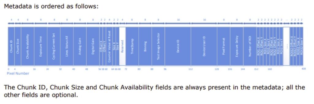
Metadata:
Metadata structure – courtesy Teledyne DALSA
Metadata may not sound very exciting, and the visuals aren’t that compelling. But sending data along for the ride with each image may be critical for quality control archiving, application analysis and optimization, scheduled maintenance planning, or other reasons of your own choosing. For example, it may be valuable to know at what shutter or gain setting an image was acquired; or to have a timestamp; or to know the device ID from which camera the image came.
The Falcon2 and Falcon4 cameras are designed for use in industrial inspection, robotics, medical, scientific imaging, as well as wide variety of other demanding automated imaging and machine vision applications requiring ultra-high-resolution images.
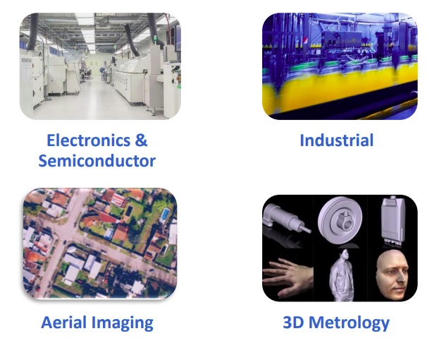
Representative application fields:
Applications for 67MP Genie Nano – courtesy Teledyne DALSA
In this article we discuss when and why one might want to strobe a light instead of using continuous lighting. While strobing traditionally required a dedicated controller, we go on to introduce that CCS and AVT have published an Application Note showing how the Allied Vision Mako camera can serve as the controller!
While LED lights are often used for continuous lighting, since that’s an easy mode of deployment, sometimes an application is best served with a well-timed strobe effect. This might be for one or more of the following reasons:
to “freeze motion” via light timing rather than shutter control alone;
to avoid the heat buildup from continuously-on lights
overwhelm ambient lighting
maximize lamp lifetime
Let’s suppose you’ve already decided that you require strobe lighting in your application. You’re past “whether” and on to “how to”.
Since you are moving into the realm tight timing tolerances, it’s clear that the following are going to need to be coordinated and controlled:
the strobe light start and stop timing, possibly including any ramp-up delays to full intensity
the camera shutter or exposure timing, including any signal delays to start and stop
possibly the physical position of real world objects or actuators or sensors detecting these
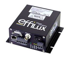
Traditionally, one used and external controller, an additional device, to control both the camera and the lighting. It’s a dedicated device that can be programmed to manage the logical control signals and the appropriate power, in the sequence required. This remains a common approach today – buy the right controller and configure it all, tuning parameters through calculations and empirical testing.
Effilux pulse controller: controls up to 4 lights; output current can reach up to 1A @ 30V in continuous and 10A @ 200V in strobe mode – courtesy Effilux
Call us if you want help designing your application and choosing a controller matched to your camera and lighting requirements.
But wait! Sometimes, thanks to feature-rich lighting equipment and cameras, with the right set of input/output (I/O) connections, and corresponding firmware-supported functionality, one can achieve the necessary control – without a separate controller. That’s attractive if it can reduce the number of components one needs to purchase. Even better, it can reduce the number of manuals one has to read, the number of cables to connect, and the overall complexity of the application.
Let’s look at examples of “controller free” applications, or more accurately, cameras and lights that can effect the necessary controls – without a separate device.
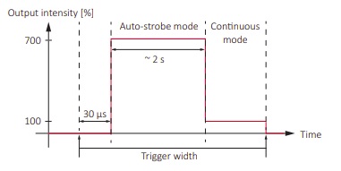
Consider the following timing diagram, which shows the behavior of the Effi-Ring when used in auto-strobe mode. That doesn’t mean it strobes randomly at times of its own choosing! Rather it means that when triggered, it strobes at 300% of continuous intensity until the trigger pulse falls low again, OR 2 seconds elapse, whichever comes first. Then if steps down to continuous mode at 100% intensity. This “2 seconds max” feature, far longer than most strobed applications require, is a design feature to prevent overheating.
Courtesy Allied Vision Technologies
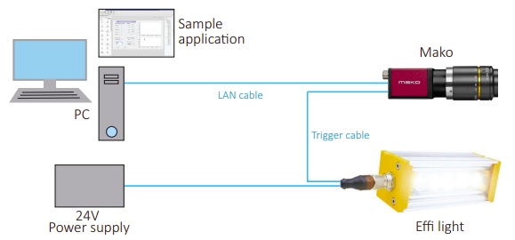
OK, cool. So where to obtain that nice square wave trigger pulse? Well, one could use a controller as discussed above. But in the illustration below, where’s the controller?!? All we see are the host computer, an Allied Vision Mako GigE Vision camera, an Effilux LED, a power supply, and some cabling.
Camera exposure signal controls strobe light – courtesy Allied Vision Technologies
How is this achieved without a controller? In this example, the AVT Mako camera and the Effilux light are “smart enough” to create the necessary control. While neither device is “smart” in the sense of so-called smart cameras that eliminate the host computer for certain imaging tasks, the Mako is equipped with opto-isolated general purpose input output (GPIO) connections. These GPIOs are programmable along with many other camera features such as shutter (exposure), gain, binning, and so forth. By knowing the desired relationship between start of exposure, start of lighting, and end of exposure, and the status signals generated for such events, one can configure the camera to provide the trigger pulse to the light, so that both are in perfect synchronization.
Note: During application implementation, it can be helpful to use an oscilloscope to monitor and tune the timing and duration of the triggers and status signals.
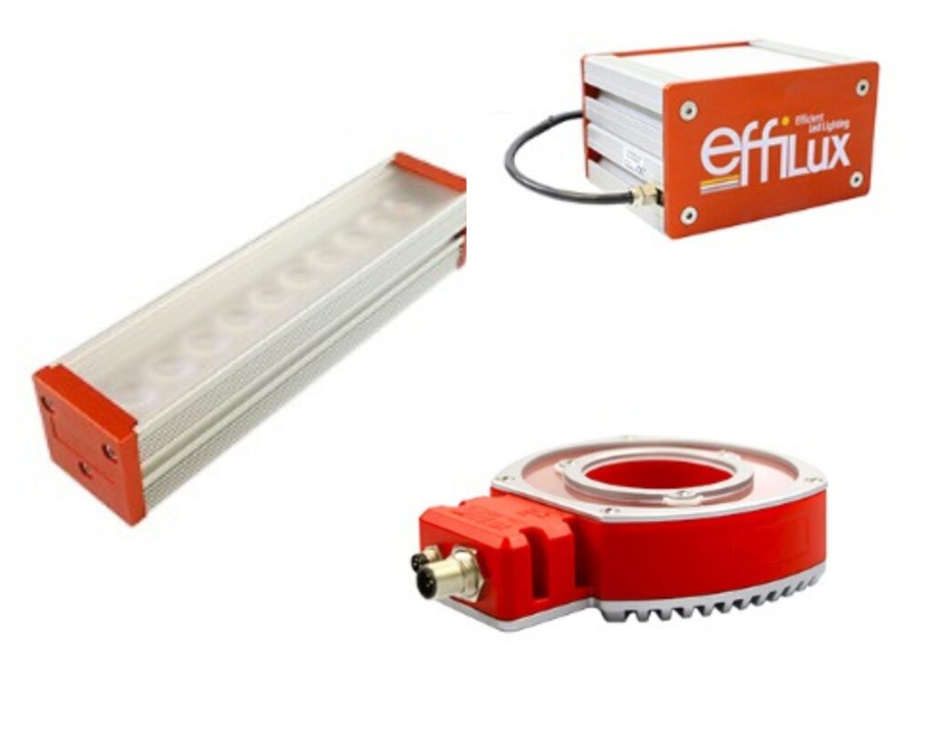
Whether your particular application is best served with a controller, or with a camera that doubles as a controller, depends on the application and camera options available. 1stVision carries a wide range of Effilux LED lights in bar, ring, backlight, and dome configurations, together with the ability to be used on continuous or strobe modes.
Lighting matters as much or more than camera (sensor) selection and optics (lensing). A sensor and lens that are “good enough”, when used with good lighting, are often all one needs. Conversely, a superior sensor and lens, with poor lighting, can underperform. Read further for clear examples why machine vision lights are as important as sensors and optics!
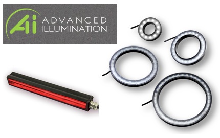
Assorted white and color LED lights – courtesy of Advanced Illumination
Why is lighting so important? Contrast is essential for human vision and machine vision alike. Nighttime hiking isn’t very popular – for a reason – it’s not safe and it’s no fun if one can’t see rocks, roots, or vistas. In machine vision, for the software to interpret the image, one first has to obtain a good image. And a good image is one with maximum contrast – such that photons corresponding to real-world coordinates are saturated, not-saturated, or “in between”, with the best spread of intensity achievable.
Only with contrast can one detect edges, identify features, and effectively interpret an image. Choosing a camera with a good sensor is important. So is an appropriately matched lens. But just as important is good lighting, well-aligned – to set up your application for success.
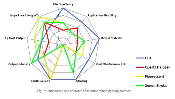
What’s the best light source? Unless you can count on the sun or ambient lighting, or have no other option, one may choose from various potential types of light:
Fluorescent
Quartz Halogen – Fiber Optics
LED – Light Emitting Diode
Metal Halide (Mercury)
Xenon (Strobe)
Courtesy of Advanced Illumination
By far the most popular light source is LED, as it is affordable, available in diverse wavelengths and shapes (bar lights, ring lights, etc.), stable, long-life, and checks most of the key boxes.
The other light types each have their place, but those places are more specialized. For comprehensive treatment of the topics summarized here, see “A Practical Guide to Machine Vision Lighting” in our Knowledgebase, courtesy of Advanced Illumination.
Download whitepaper
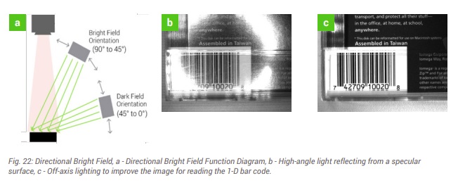
Lighting geometry and techniques: There’s a tendency among newcomers to machine vision lighting to underestimate lighting design for an application. Buying an LED and lighting up the target may fill up sensor pixel wells, but not all images are equally useful. Consider images (b) and (c) below – the bar code in (c) shows high contrast between the black bars and the white field. Image (b) is somewhere between unusable or marginally usable, with reflection obscuring portions of the target, and portions of the (should be) white field appearing more grey than white.
Courtesy of Advanced Illumination
As shown in diagram (a) of Figure 22 above, understanding bright field vs dark field concepts, as well as the specular qualities of the surface being imaged, can lead to radically different outcomes. A little bit of lighting theory – together with some experimentation and tuning, is well worth the effort.
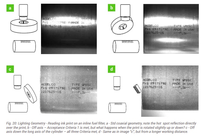
Now for a more complex example – below we could characterize images (a), (b), (c) and (d) as poor, marginal, good, and superior, respectively. Component cost is invariant, but the outcomes are sure different!
Color light – above we showed monochrome examples – black and white… and grey levels in between. Many machine vision applications are in fact best addressed in the monochrome space, with no benefit from using color. But understanding what surfaces will reflect or absorb certain wavelengths is crucial to optimizing outcomes – regardless of whether working in monochrome, color, infrared (IR), or ultraviolet (UV).
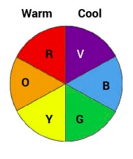
Beating the same drum throughout, it’s about maximizing contrast. Consider the color wheel shown below. The most contrast is generated by taking advantage of opposing colors on the wheel. For example, green light best suppresses red reflection.
Courtesy of Advanced Illumination
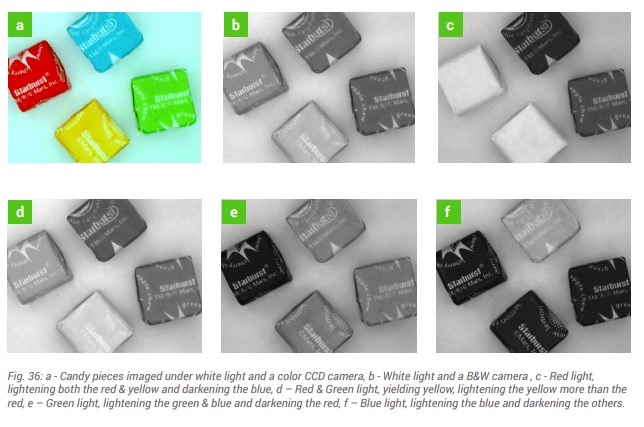
On can use actual color light sources, or white light together with well-chosen wavelength “pass” or “block” filters. This is nicely illustrated in Fig. 36 below. Take a moment to correlate the configurations used for each of images (a) – (f), relative to the color wheel above. Depending on one’s application goals, sometimes there are several possible combinations of sensor, lighting, and filters to achieve the desired result.
Courtesy of Advanced Illumination
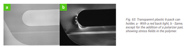
Filters – can help. Consider images (a) and (b) in Fig. 63 below. The same plastic 6-pack holder shown is shown in both images, but only the image in figure (b) reveals stress fields that, were the product to be shipped, might cause dropped product, reduced consumer confidence in one’s brand. By designing in polarizing filters, this can be the basis for a value-added application, automating quality control in a way that might not have been otherwise achievable – or not at such a low cost.
Courtesy of Advanced Illumination
For more comprehensive treatment of filter applications, see either or both Knowledgebase documents:
Powering the lights – should the be voltage-driven or current-driven? How are LEDs powered? When to strobe vs running in continuous modes? How to integrate light controller with the camera and software. These are all worth understanding – or having someone in your team – whether in-house or a trusted partner – who does.
For comprehensive treatment of the topics summarized here, see Advanced Illumination’s “A Practical Guide to Machine Vision Lighting” in our Knowledgebase:
Download whitepaper
This blog is intended to whet the appetite for interest in lighting – but it only skims the surface. Machine vision lights as important as sensors and optics. Please download the guide linked just above – to deepen your knowledge. Or if you want help with a specific application, you may draw on the experience of our sales engineers and trusted partners.