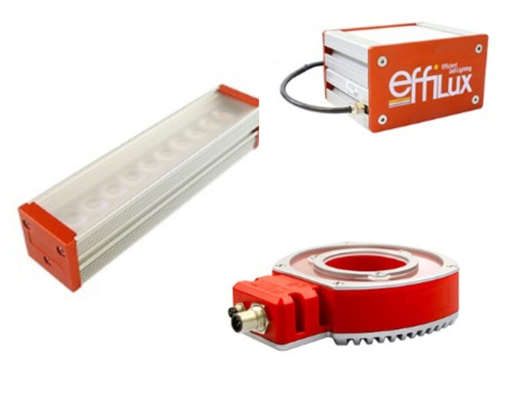
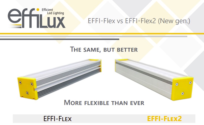
EFFI Flex2 LED bar lights are the next generation modular lights with even more flexibility.
Getting the lighting right is as important as choosing the right sensor, camera, and interface, in terms of machine vision success. Most all lights are “pre-configured” to a specific lighting geometry as well as wavelengths. Lighting is still tricky and in most cases, testing is needed with various configurations. If your samples are small in size and don’t require special handling or equipment, your imaging partner may offer a lighting lab in which they can test your samples to optimize lighting configuration.
But shipping samples and re-creating your conditions in a partner’s lab isn’t always practical, and you may want to do your own testing and configuration, taking advantage of your domain expertise and home-field advantage. With EFFI Flex2 lights, the standard components and range of settings yield 36 configurations in 1 light! How so? Each unit comes with 3 diffuser windows x 4 lens positions x 3 electronic modes = 36 configurations. Optional additional accessories, like polarizers, take the calculation to more than 100 configurations!
EFFI Flex2 LED modular bar lights are configurable to a wide range of applications. The user can adapt the optics, the electronics, and the mechanics, thanks to the engineering design. Perhaps you’ll embed the unit in a “forever” deployment mode, never again re-configuring a specific unit once you lock down the optimal settings.
Or maybe you’ll adapt your light again to repurpose it in another application. With the long service life of LED lights, the light may well outlive the application. Or maybe you do multiple applications, and want a light that’s so versatile you can do all your testing in house, letting the lighting drive the final choice of sensor and camera model.
As with the first generation EFFI-Flex product, EFFI-Flex2 series is designed to provide easy adaptation of:
- Optics – adjust the lens position and the diffusers
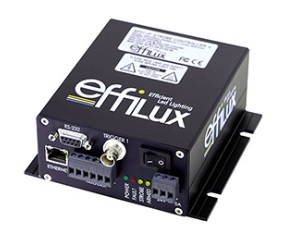
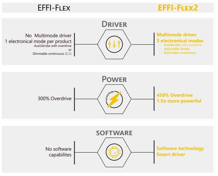
- Electronics – built-in multimode driver offers 3 operating modes in one light
- Mechanics – optical lengths from 60mm – 2900mm (factory configured)
Optically, lens positions may be user-adjusted for emission angles ranging from from 90 to 10 degrees. Each unit ships with swappable diffusers for strobed light, diffused, semi-diffused, or opaline light. Further, if necessary for your particular application, optional optical accessories are available: polarizer, linescan film, and cylindrical lens).
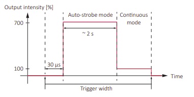
Electronically, the built-in multimode driver features 3 electronic modes: AutoStrobe with 450% Overdrive, Adjustable Strobe with controlled intensity from 10% to 100%, and Dimmable Continuous with controlled intensity from 10% to 100%. The 450% Overdrive mode is 1.5 times more powerful than the original EFFI-Flex LED bar light in overdrive.
The driver software makes it easy to select among the 3 modes, and the parameters within each mode.
Mechanics: While the length of a given unit cannot be adapted once delivered, one may order in lengths from as short at 60mm to as long as 2900mm. If your default units are English rather than metric, that’s from less than 3 inches to as much as 9.5 feet!
EFFI-Flex original series remains in production. If you don’t require the flexibility of EFFI-Flex2, with up to 36 configurations per unit shipped, the original series offers great value in its own right. Call us at 978-474-0044 to speak with one of our sales engineers, for guidance, or take out your own appendix with this side-by-side comparison diagram:

1st Vision’s sales engineers have over 100 years of combined experience to assist in your camera and components selection. With a large portfolio of lenses, cables, NIC card and industrial computers, we can provide a full vision solution!