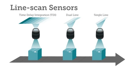
TDI is based on the concept of accumulating multiple exposures of the same (moving) object, effectively increasing the integration time available to collect incident light. The object motion must be synchronized with the exposures to ensure a crisp image.
Context
If an object were stationary, and one wasn’t in a hurry, one could just do a longer exposure in order to achieve an ideally saturated image. But the object in question is in fact moving. And it’s a line scan application. Each line exposure is extremely fast, so there’s not much opportunity to accumulate sufficient light into the sensor.
Candidate solutions
Use “faster” sensor that is more sensitive in low light situations? Conceptually plausible but not always available relative to speed of motion and available light.
Introduce artificial light? Usually one already adds concentrated light with line scan, but for challenging applications it may not be sufficient… relative to the speeds one hopes to attain.
Use Time Delay Integration (TDI) to build up final image as composite from multiple exposures carefully synchronized to object’s motion. Key concept: the object is moving anyway, so take advantage of that movement as an opportunity to get multiple “looks” at the same slice of the object. A variation on “when given lemons make lemonade”.
See the video below for an illustrative simulation. The conceptual application is mail processing, where the goal is to read whether a letter is stamped, with which denomination of postage, all while the letter is moving at continuous speed along a conveyor belt, lit only by ambient or low intensity light.
The memory summing of the successive exposures builds the readout image.
Benefits
Speed: You can increase the speed of the target object or inspection web, improving overall throughput. This alone may be a huge competitive advantage.
Lower lighting costs: Get by with just one instead of two lights, and perhaps just a modest light rather than a high-intensity one.
Signal to noise ratio: SNR is improved. Since multiple exposures are summed, useful image signal increases while random noise is reduced. This gives cleaner images and better defect detection.
Tradeoffs
Clearly sufficient synchronization must be achieved for TDI to work effectively. Thankfully the synchronization doesn’t have to be perfect – a TDI device can comfortably tolerate a 2-4% velocity mismatch between inspection web and imager. This is not difficult to achieve using a web-mounted encoder to supply a sync signal to the camera, even with webs that change speed. There are thousands of successful implementations.

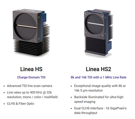
For a wide range of line scan products, the the Teledyne DALSA Linea families. For TDI in particular, drill in on the Linea HS and Linea HS2 products.
Applications
Typical applications include, but are not limited to:
- Semiconductor wafer inspection
- High-density interconnect inspection
- Quality control on flat panel displays
- Some life science applications
In a nutshell, if it’s “light starved” and line scan, TDI can be the answer.

1st Vision’s sales engineers have over 100 years of combined experience to assist in your camera and components selection. With a large portfolio of cameras, lenses, cables, NIC cards and industrial computers, we can provide a full vision solution!
About you: We want to hear from you! We’ve built our brand on our know-how and like to educate the marketplace on imaging technology topics… What would you like to hear about?… Drop a line to info@1stvision.com with what topics you’d like to know more about.
#Timedelayintegration
#TDI
#Linescan