Learn about the new 5GigE camera interface

Dalsa Nano 5GigE

Machine vision interfaces have continued to evolve over the years increasing data throughput and cable lengths.  Commonly used interfaces are GigE and USB3.  However, 5GigE is an interface now gaining attention in the industrial imaging / machine vision market with some nice advantages.

We will outline the benefits of 5GigE, but first, lets give a brief overview of the commonly used camera interfaces, with their pluses and minuses:

GigE  / GigE Vision

  • 110 MB/s of sustainable throughput.  In real world terms, a HD, 2MP camera can get 50-55 fps in 8 bit mono or 8 bit color mode.  Note, this isn’t real HD, since you need 60 FPS.
  • Data cable lengths up to 100m using regular CAT 5e/6 cable.
  • Easy to put multiple cameras on a system.

USB 3 / USB3 Vision

  • 420 MB/s of data throughput.    A HD 2MP camera can run 60 fps in 8 bit mono or color and can  also run RGB at 60 FPS no problem.  With the higher throughput,  a 5MP camera can achieve 85 fps in 8 bit mode.
  • Data cables up to 5 meters and up to 20 meters with active cables. However, active cables can be quite costly, adding up to $200 in cost.
  • Not as easy as GigE to put multiple cameras on a system, and gets harder with each additional camera, especially if you have limited USB3 controllers.

As a note, there is no cost difference when using cameras with the same sensor from the same manufacturer with USB or GigE!  They will cost about the same with no premium for one interface over the other.

gige nano 5gigeWhat are the limitations of GigE and USB3 now solved by 5GigE?

  • USB3 is limited in cable length, so going faster than GigE is great, but you can not have long cable lengths.
  • GigE has cable lengths up to 100 meters, but is limited to ~ 110MB/s of data, so you do not have the high frame rates as in a USB3 camera.
  • USB3 in 4+ camera systems is not as stable as GigE AND you’re still limited on cable lengths.

Wait! – What about 10GigE? 

Up until now, 10G was the next interface. However, the jump to 10G has quite a few limitations as outlined below.

  • Heat generation is significant, so cameras are large and not in the smaller 29 x 29mm cube form factor.
  • Not a lot of demand for very high speed 10G, so not a lot of sensors being offered
  • Minimal number of manufacturers for 10G, higher cost.
  • Special cabling, either optical or high quality cat 7.

What we have found is that there are several types of applications for 10G cameras and are as follows

  • Applications where you need 10G of speed of course (high resolution + fast frame rates)
  • Require greater than  110MB/s of data and need long cable lengths.
  • Where there is the required combination of 110MB/s for high frame rates, multiple cameras and long cable lengths, 10G is a perfect solution.

We have seen that the need for higher bandwidth + long cable lengths is more prominent vs. the real need for 10GigE!

 Introducing 5GigE that provides increased bandwidth, long cable lengths at reasonable prices! or N Base T.5GigE machine vision applications

5GigE (also known as N Base T) has become a new standard for industrial, machine vision cameras.

In the general compute world, a much much larger market than vision, there has also been a need to go faster than GigE. However, the issue of replacing the existing cabling is the major issue preventing this. If you think of a big box store, say a Home Depot for instance, the amount of cabling is huge. Ripping that out and rewiring far exceeds the cost of the equipment to use it!

5G was made to go faster, but use existing cabling. Regular cat6e cable can be used, and 5G is a subset of 10G, so all switches etc. can be kept in service.

5G gives users in the vision market USB3 speeds, but with ALL of the regular GigE features, at a very small premium!

get quote1st Vision’s sales engineers have over 100 years of combined experience to assist in your camera selection.  With a large portfolio of lenses, cables, NIC card and industrial computers, we can provide a full vision solution!


Get a 5MP lens for the price of a 3MP one! FUJI’s new XA-5M lenses.

FUJI LensesFujinon introduced their first 5MP series, the  5MP SA-1s  over a decade ago. Back then they were the first really high quality lenses for under $500.

Now, they have introduced their next generation 5MP series,  the new XA-5M ,  and they have made them smaller, better, and less expensive!  Now you can get a 5MP rated lens for very close to what 2 or 3MP lens cost with the new HF-XA-5M series lenses!  1stVision has preferred pricing and stock!   Contact us for a quote

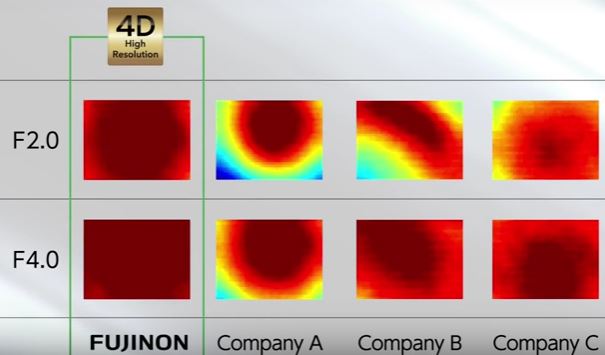
The Fujinon XA-5M are designed to work at 3.45um resolution (and very good at 2.5um), so they are a great choice for the 3.45um pixels found in the Sony Pregius IMX line of sensors.  See image below showing a heat map of the resolution.(Darker red is higher resolution, 2.7um, orange is 3.3, yellow is 4um, light blue is 5um, and dark blue is 6um)

FUJI resoltion chart

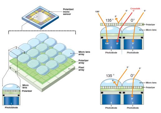
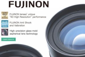
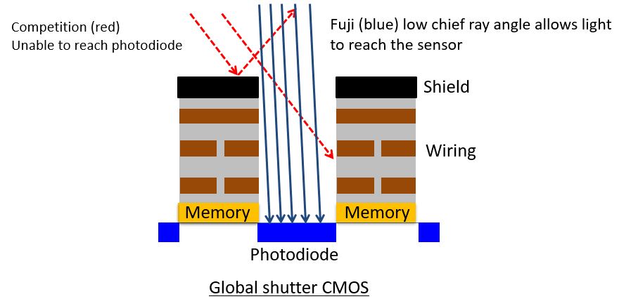
Further, the new CMOS sensors have more of a ‘stacked’ architecture, meaning each pixel is tall.  Without having a lens that has a small chief ray angle, which keeps the light rays as close to perpendicular as possible to the sensor, each pixel possibly shades its neighbor.  The new Fujinon lenses are designed to solve that problem for these sensors.  So when comparing this line to their competitors, there is less shading at the edges and more even illumination!

Get quote on FUJI lens

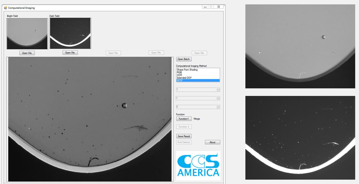
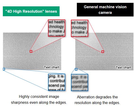
The results can be seen when comparing the center to edges in an application.  In the example below, the text in the center and edge on the FUJI “4D High Resolution” lenses is crisp vs the competition on the right.

FUJI HF-XA 5M resolution textFinally, Fujinon has dramatically reduced the size of the lens, all the lenses are 29.5mm in diameter except the 6mm, which is 39.5mm.   Now you can get a 5MP rated lens for very close to what 2 or 3MP lens cost with the new HF-XA-5M series lenses!  1stVision has preferred pricing and in stock!   Contact us for a quote

Watch this video for more details on how the HF-XA-5M lenses compare to the competition

1st Vision’s sales engineers have over 100 years of combined experience to assist in your camera selection.  With a large portfolio of lenses, cables, NIC card and industrial computers, we can provide a full vision solution!

Related Videos – FUJI is now incorporating anti-shock and vibration into their lens series!

Related Posts

Not All Lenses are Created Equal! Lens MTF Comparisons

There is NO such thing as a “Megapixel” machine vision camera lens!.. Say what??

Learn about CoaXpress and frame rates achievable with Allied Vision’s “Bonito Pro” cameras with CXP-6

Allied Vision Bonito Pro camera

What is  CoaXPress, especially with “CXP-6” capability?

CoaXPress is an established industry standard allowing high speed communications over coaxial cable.  The current version supports bit rates up to 6.25 Gbits/sec over a single coaxial cable.  When used in parallel, two or more coaxial cables can provide incremental speed gains.  The naming convention associated with CoaXPress signify the bit rate as seen in the chart below.   In cases that you see CXP-6 has a bit rate of 6.25 Gb/s.  The 4 x means the number of lanes. Multiply the 2 and you get your total bit rate.

CXP CoaXpress

The new Allied Vision Bonito Pro cameras utilize 4 DIN 1.0/2.3 connectors on a CXP-6 interface (4 lanes) x 6.25Gbits/Sec. This  allows for resolutions of up to 26 megapixels to reach 70 frames per second (fps).  The first two Bonito PRO models (Bonito PRO X-2620 and X-1250) support high resolution with 26.6MP and 12.5MP at 80 and 142 fps respectively.

The Bonito PRO cameras are ideal for a wide range of applications including, 2D/ 3D surface inspection,  high speed printing, PCB & Electronics inspection.

Even faster frame rates can be achieved using the Bonito Pro X1250 (12.5MP) in partial scan mode.  Set to a 768 line height, a rate of 503 fps can be achieved!

Bonito Pro frame rates

The following video’s are good representations of what this relates to in real applications which you can appreciate.

Full specifications for the Allied Vision Bonito Pro cameras can be found HERE, but main features and benefits include:

  • Sensors available in Monochrome (X-1250B) and Color (X-1250C) and extended near-infrared (X1250B NIR ) models
  • On board defect pixel and 2D fixed pattern noise correction for improved image quality
  • Fan-less design for industrial imaging applications.
  • DIN 1.0 / 2.3 CoaXPress connections for secure operation in industrial environments.
  • Single cable solutions using trigger and power over CoaXPress (PoCXP)

contact us1st Vision’s sales engineers have over 100 years of combined experience to assist in your camera selection.  With a large portfolio of lenses, cables, NIC card and industrial computers, we can provide a full vision solution!


UPDATE:  New video of the Bonito Pro detailing the multi-ROI function


Dalsa Nano M2450 polarized camera: Resolving defects that are undetectable with traditional imaging!

Dalsa Polarization camera

Genie Nano cameraThe first Genie Nano camera model with a quad-polarizer filter using the Sony Pregius IMX250-MZR 5.1MP monochrome image sensor is now available.  The Teledyne Dalsa Nano M2450 camera incorporates the nanowire polarizer filter allowing detection of both the angle and amount of polarized light.

What problems can the Nano M2450 polarized camera solve?

Polarized filtering can reduce the effects of reflections and glare from multiple directions and reveal otherwise undetectable features in the target scene.  Polarization enables detection of stress, birefringence, through-reflection and glare from surfaces like glass, plastic, and metal.  Sony’s newest image sensor, with its pixel-level polarizer structure, enables the detection of both the amount and angle of polarized light across a scene. Dalsa Nano polarization camera


Four different angled polarizers (90°, 45°, 135° and 0°) are positioned on each pixel, and every block of four pixels comprises a calculation unit.Contact 1st vision for pricing

How does polarization work?  Theory of operation

Polarization direction is defined as the electrical direction.  Light, with its electrical field oscillating perpendicular to the nano wire grid, passes through the filter while that in the parallel direction is rejected.

For Polarized light, only the portion of the light vector perpendicular to the angle of the nanowire filter grid passes.

polarization filter

For example, with a wire-grid polarizer filter at 90 deg. to the maximum transmission is for polarized light at an angle of 0 deg.

polarizer filterThe polarizer filter is placed directly on the sensor’s pixel array, beneath the micro-lens array.  This design, compared to polarize filters on top of the micro lens array reduced the possibility of light at a polarized angle being misdirected into adjacent pixels (cross talk) and incorrectly detected at the wrong angle.

Dalsa polarizer filter theory

The Genie Nano’s polarizer filter on the camera sensor is a 2 x 2 pattern, with each pixel having a nanowire polarizer filter with different angles (90, 45, 135 and 0 degree’s)

The image output pattern of the monochrome camera is arranged in 2 x 2 pixel block as follows:

Pixel blocks


That is, the first line output is an alternating sequence of pixels 0 & 35 degrees, with the following line of 45 and 90 degrees.

Given the proportion of light available through these four filters, any angle of polarized light can be calculated. Any given state of polarization can be composed by two linearly polarized waves in perpendicular directions. The state of polarization is determined by the relative amplitude and difference in phase between the two component waves.

Calculations on the 2×2 filter blocks result in a single pixel for each polarizer filter angle, therefore the resulting image is one fourth the original image resolution. For example, with an original image of 2464×2056, the resulting image is 1232×1028 (original buffer width/2 and original buffer height/2) for a single polarizing angle.

resulting image

Teledyne Dalsa offers a Polarization demo user interface making it easy to test the polarization techniques for various applications.  This includes the ability to see the results of various processing algorithms with the summed images.

Dalsa Polarization demo
As part of the demo program, images can be displayed with pseudo-color mapping

In summary, the new Dalsa Nano M2450 polarized camera can help resolve defects not detected by traditional imaging!   Contact 1st Vision to arrange a camera demo in which we will provide the demo polarization software as well or discuss your application.  Or click HERE to request a quoteContact us


Need line scan?  – With the addition of the Genie Nano polarized model, Teledyne DALSA is the first company to offer polarization for both area and line scan (Piranha™4 polarization) cameras

1st Vision’s sales engineers have over 100 years of combined experience to assist in your camera selection.  With a large portfolio of lenses, cables, NIC card and industrial computers, we can provide a full vision solution!

Related Posts

Dalsa line scan polarization camera makes invisible visible!

Teledyne Dalsa TurboDrive 2.0 breaks past GigE limits now with 6 levels of compression