Optotune liquid lenses – 5 case examples for machine vision

Optotune tunable lenses

Optotune & Gardasoft liquid lens controlsLiquid lens technology, with its ability to change focus within the order of milliseconds is opening up a host of new applications in both machine vision and the life sciences.  It is gaining growing interest from a wide cross section of applications and easily adapts to standard machine vision lenses.

Liquid lens technology alone provides nice solutions, but when combined with advanced controls, many more applications can be solved.

To learn the fundamentals of liquid lens technology and download a comprehensive white paper read our previous blog HERE. 

see spec's

In this blog, we will highlight several case application areas for liquid lens technology.

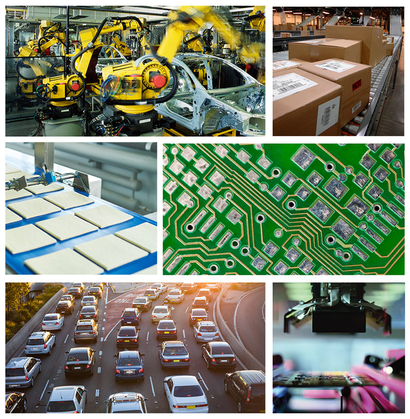
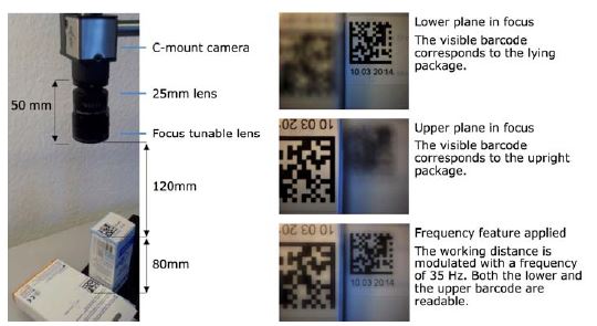
Case 1:  Applications requiring various focus points and extended depth of field:  This does cover many applications, such as logistics, packaging and code reading in packaging.  Optotune Liquid lenses provide the ability to have pre-set focus points, auto-focus or utilize distance sensors for feedback to the lens.  In the example below, 2 presets can be programmed and toggled to read 2D codes at various heights essentially extending the depth of field.

extended DOF

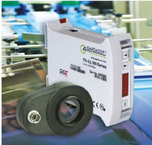
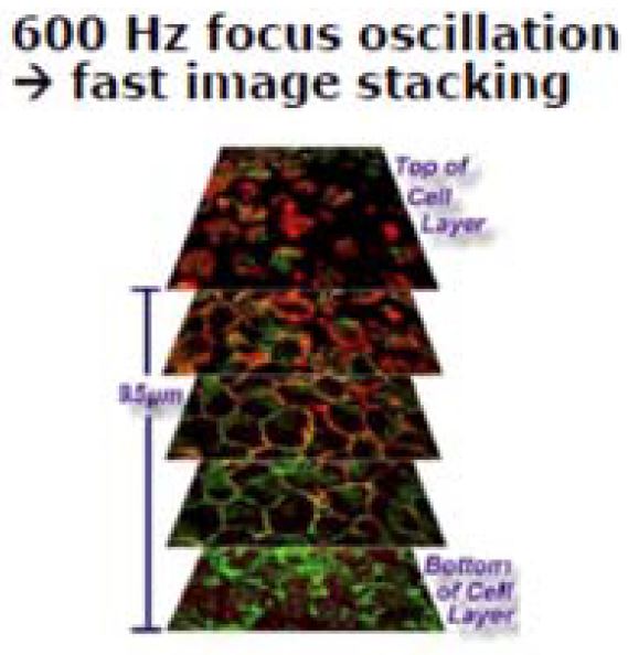
Case 2:  3D imagery of transparent materials / Hyperfocal (Extended DOF Images:  When image stacking
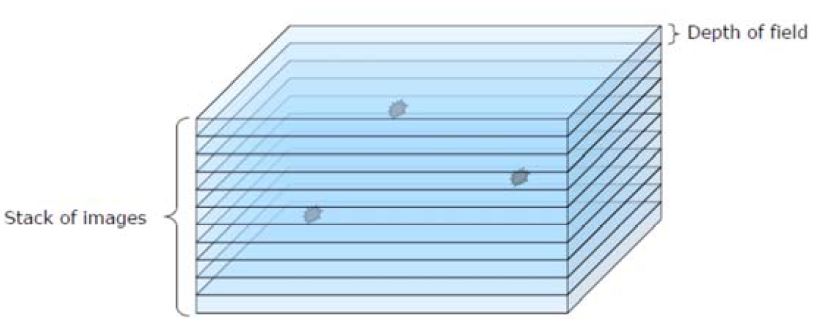
using an Optotune liquid lens in conjunction with a Gardasoft TR-CL180 controller, sequence of images can be taken with the focus point stepped between each image.  This technique is known as focus stacking.   This will build up a 3D image of transparent environments such as cell tissue or liquid for analysis.  This can also be used to find particles suspended in liquids.

image stacking for cells

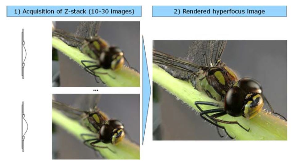
A Z-stack of images can also be used to extract 3D data (depth of focus) and compute a hyper-focus or extended depth of field (EFOF) image.

The EDOF technique requires tacking a stack of individual well focused images which have preferably been synchronized with one flash per image.  An example is show below with the rendered hyper focus image shown at right.

Hyperfocus imageCase 3:  Lens inspection:  Liquid lenses can be used to inspect lenses, such as those in cell phones for dust and scratches looking through the lens stack.

Optotune liquid lens stack image
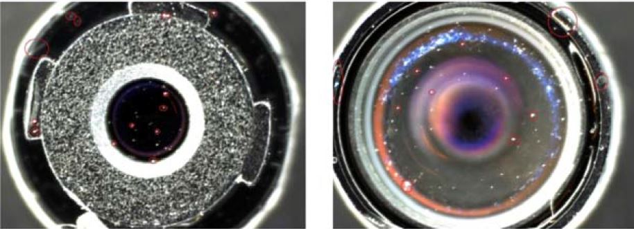
For this application, a liquid lens is used in conjunction with a telescentric lens taking images through different heights of the lens stack.  

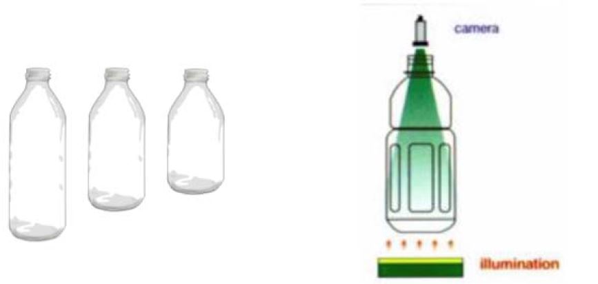
Case 4:  Bottle / Container inspection:  Optotune Liquid lenses can be used to facilitate image bottom’s of glass bottles or containers of various heights.

In this example, the camera is consistently at the neck of the bottle, but the bottom is at different heights.  optotune lens - bottle inspection

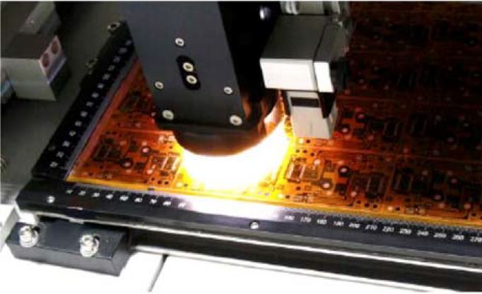
Case 5:  Large surface inspections with variation in height:  Items ranging from PCB’s to LCD’s are not flat, have various component heights and need to be inspected at high magnification (typically using lenses with minimal DOF).  Optotune Liquid lenses are a perfect solution using preset focus points.

pcb inspection

Machine Vision applications using Optotune Liquid lenses and controller are endless!

These applications are just the tip of the iceberg and many more exist, but this will give you a good idea of capabilities.   Gardasoft TR-CL controllers are fully GigE Vision compliant, so any compatible GigE Vision client image processing software such as Cognex VisionPro, Teledyne Dalsa Sherlock or National Instruments LABVIEW can be used easily.

Click to contact

1st Vision’s sales engineers have over 100 years of combined experience to assist in your camera selection.  With a large portfolio of lenses, cables, NIC card and industrial computers, we can provide a full vision solution!

Contact us to help in the specification and providing pricing

Ph:  978-474-0044  /  info@1stvision.com  / www.1stvision.com

Related Video

Related Blog Posts

Learn how liquid lenses keep continuous focus on machine vision cameras when the working distance changes.

New 1.1” FUJINON CF-ZA-1S Series machine vision lenses with 2.5um pixel resolution – Best in class

FUJI

FUJI lensesFUJINON has released its new CF-ZA-1S lens series supporting high resolution 1.1″ format images sensors down to 2.5um pixel pitches.  This new series has some unique differences making it our go-to lens for this format size.

In this blog, we cover the unique differences, which are at a price point equal to or lower than competing brands, making it the best in its class.

The FUJINON CF-ZA-1S series with support of 2.5um pixels can be used essentially with any image sensor up to 1.1″ formats needing resolution for small pixels.  Focal lengths from 8mm to 50mm are available.FUJI CFZA-1S models

contact us

CLICK HERE FOR FULL SPECIFICATIONS ON THE FUJINON CF-ZA-1S LENSES

Main Features of the FUJINON CF-ZA-1S machine vision lens series

High resolution and support of 2.5um pixels from center to edge
FUJINON’s
“4D High Resolution” keeps uniform resolution from the image center to the peripherals regardless of lens working distance and f-stop.   This is extremely beneficial in applications in which high contrast is needed from center to edge. (i.e Measurement of a part spanning the field of view)FUJI 4D high resolutionRelative illumination reaches 90% +
In general, the illumination of the peripheral areas of the image is determined by the “relative illumination” and the chief ray angle (CFA).  FUJINON has designed the lens series to constrain the CRA allowing a good balance to the peripherals of the image as seen below.   For machine vision applications needing even illumination, this becomes very important for repeatability.  Chief ray angle - FUJINON

Vibration and Impact resistant
FUJINON has done a great job within their new lens series to incorporate anti-vibration and resistance to high impacts for no extra cost!  In applications such as robotic applications, autonomous vehicles and airborne applications to name a few will benefit from this feature.  FUJI anti-vibration

This video highlights these features and more.   It nicely details how the design constraints the CFA for even illumination and is a nice tutorial.

Contact us to talk to an expert!

1st Vision’s sales engineers have over 100 years of combined experience to assist in your camera selection.  With a large portfolio of lenses, cables, NIC card and industrial computers, we can provide a full vision solution!

Ph:  978-474-0044  /  info@1stvision.com  / www.1stvision.com

Related Blogs

What are the f-numbers on machine vision camera lenses? f-stop explained!

Get a 5MP lens for the price of a 3MP one! FUJI’s new XA-5M lenses.

Not All Lenses are Created Equal! Lens MTF Comparisons

Basic guidelines in selecting a machine vision camera interface

Machine Vision InterfacesIndustrial machine vision camera interfaces have continued to develop allowing cameras to transfer megapixel images at extremely high frame rates.  These advancements are opening up endless applications, however each machine vision camera interface has its own pro’s and con’s.

Selecting the best digital camera interface can be done by taking in several considerations first and in doing so, can window down your selection.

The following are some considerations in making an interface selection.

  1. Bandwidth (Resolution and frame rate)
  2. Cable Length
  3. Cost
  4. Complexity

Bandwidth:  This is one of the biggest factors in selecting an interface as it essentially is the size of the pipe to allow data to flow.  Bandwidth can be calculated by resolution x frame rate x bit depth.   You essentially find out pixels / second x the frame bit depth resulting in your total Megabits / second (Mb/sec).  Large frame sizes at high speeds will require a large data pipe!  If not, you’ll be bandwidth limited, so one would need to reduce the frame rate and image size or a combination of both.

Cable Length:  The application will dictate the distance between the camera and industrial computer.  In factory automation applications, the cameras can be located in most cases within meters from the computer vs a stadium sports analytics application requiring 100’s of meters.

Cost:  Budgets dictate in most cases, so this must also be considered.  Interfaces such as USB are very low cost versus a CoaxPress interface which will require a $2K frame grabber and more expensive cables.

Complexity:  Not all interfaces are plug and play and require more complex configuration.  If you are leaning towards interfaces using frame grabbers and have no vision experience, you may want to elect using a certified systems integrator.

The considerations above will start to dictate the interface for the machine vision application.  The chart below provides an overview to help in the selection process.  machine vision interface chartFor a PDF of this chart, please email jonc@1stvision with subject “Interface chart”

Digital machine vision camera interfaces.

The interfaces each have pro’s and con’s aside from the designated bandwidth, cable lengths and costs, and outlined as follows:

USB2.0 is an older standard for machine vision cameras and now superseded by USB3.0 / 3.1 .  Early on, this was popular allowing cameras to easily plug and play with standard USB ports.  This is still a great option for lower frame rate applications and comes with low cost.  Click here for USB2 cameras.

USB3.0 / 3.1  is the next revision of USB2.0 allowing high data rates, plug and play capabilities and is ratified by the AIA standards, being “USB3 Vision” compliant.  This allows plug and play with 3rd party software following the GENICAM standards.  Cables lengths are limited to 5 meters, but can be overcome with active and optical cables.   Click here for USB3 cameras

GigE Vision was introduced in 2006 and is a widely accepted standard following GENICAM standards.  This is a the most popular high bandwidth interface allowing plug and play capabilities and allowing long cable lengths.  Power Over Ethernet (PoE) will allow 1 cable to be used for data and power making a simpler installation.  GigE is still not was fast as USB3.0, but has benefits of 100 meter cable lengths.  Click here for GigE cameras.

5 GiGe (aka N-base T) & 10GigE similar to USB2 moving to USB3, is the next iteration of the GigEVision standard providing more bandwidth.   Both follow the same GigE Vision standards, but now at higher bandwidths.  Specific NIC cards will be required to handle the interface.  Click here for 5 GigE cameras. 

CoaxPress (CXP) is a relatively new standard released in 2010, supported by GENICAM, utilizing coax cable to transmit data, trigger signals and power using one cable..  It is a scaleable interface via additional coax cables supporting up to 25Gb/s (3125MB/s) and higher now with CXP12.  The interface can support extremely high bandwidth as seen in the above chart with long cable lengths to 100+ meters depending on the configuration.  This interface requires a frame grabber which adds cost and some complexity in the overall setup.  Click here for CoaxPress cameras

Camera link is a well established standard, dedicated machine vision standard released in 2000 allowing high speed communications between cameras and frame grabbers.  It includes provisions for data, communications, camera timing and real time signaling to the camera.  A frame grabber is required similar to CXP adding cost and some complexity and is limited in cable lengths to 10 meters.  Longer cable lengths can be achieved with active and fiber optic cable solutions which additionally add cost.   Click here for CameraLink cameras

CameraLink HS is a dedicated machine vision standard taking key aspects of CameraLink and expanding upon it with more features.  This is a scaleable high speed interface with reliable data transfer and long cable lengths up to 300+ meters with low cost fiber connections.  Similar to CXP and camera link a frame grabber is required adding cost.  Click here for Cameralink HS cameras

Some caveats:  In calculating bandwidth, you can calculate the theoretical data rate, but in some interfaces, the real world practical will be different.  In Camera link and CoaxPress, the theoretical and practical are the same.   In Cameralink HS, limits will be set by the computer interface (i.e PCIe x 8, Gen 3 is 6.8 Gigabyte / sec and an Xtium CHLS frame grabber can capture 7 Gigabyte / sec!)

The theoretical and practical limits for USB and Ethernet can be quite different and there will always be some difference.  For example, large frames and low frame rate generates less interrupts, providing less overhead to the CPU.   A small frame with high frame rate generates more interrupts causing more load to the CPU.

Click to contact As a note:  This blog post covers the basics of each of the interfaces.  There is much more information 1stVision can share with you to be sure you are taking all aspects of the vision application into consideration.  We have several additional resources we can share to help, so don’t hesitate to contact us for free consultation!

1st Vision’s sales engineers have over 100 years of combined experience to assist in your camera selection.  With a large portfolio of lenses, cables, NIC card and industrial computers, we can provide a full vision solution!

Ph:  978-474-0044  /  info@1stvision.com  / www.1stvision.com

Related Blogs

Learn about the new 5GigE camera interface

Learn about CoaXpress and frame rates achievable with Allied Vision’s “Bonito Pro” cameras with CXP-6

What Is Offered in an Industrial PC Machine Vision Computer?

What are the f-numbers on machine vision camera lenses? f-stop explained!

machine vision lens

Why does 1stVision focus (no pun intended) so much on machine vision lenses.  As the old saying goes, if you have garbage in, you get garbage out.

The lens is the input to the machine vision system.  A low quality lens means that you have already degraded the image coming into the sensor.  For instance, let’s say you chose a camera with 5um pixels, which equates to a lens being able to resolve 100 lp/mm.  If your lens’ Modular Transform Function (MTF) is only 50 lp/mm, you should have chosen a camera with 10um pixel size, because the lens can’t do any better than that.   As a note, don’t infer that a camera with 10um pixels is worse than a camera with 5umpixels from this example, as that is not true.  Learn more on MTF here

Click hereA machine vision lens gathers light and then focuses it.  When we talk about focus, we are talking about the MTF, but when we discuss light gathering properties, we need to discuss the lens f-number.

FUJI -f-stop
FUJI lens showing f-stops
f-number
The f-number is defined as the ratio of the focal length by the aperture width (diameter of the entrance pupil).  So a 50mm focal length lens with a f-number of 2 has a 25mm entrance pupil.  The lower the f-number, the more light  will be allowed into the system, however this equates to more expensive  lens as you need more glass to make a wider entrance pupil.

f-stop
Many camera lenses have an adjustable iris that opens and closes at the front of the lens to limit the amount of light coming in.  When open all the way, the f-stop is the f-number.  From there, each f-stop from wide open halves the amount of light, which corresponds to reducing the size of the aperture by 1/sqrt(2) or about 0.707 and in turn halving the area.

f-number
Diagram of decreasing apertures, that is, increasing f-numbers, in one-stop increments; each aperture has half the light-gathering area of the previous one.

The f-stop is represented by a sequence of these numbers below, each letting in half the light.

Sequence:  f/1, f/1.4, f/2, f/2.8, f/4, f/5.6, f/8, f/11, f/16, f/22, f/32, f/45, f/64, f/90, f/128

The sequence is obtained by approximating the geometric sequence

s-stop sequence

Characteristics of the f-stop

  • Most lenses are designed to be optimal in the F4-F5.6 range, in which they have the best MTF.
  • The higher f-number (ie f/8 ) is, or the more closed the aperture is, better the depth of field if achieved
  • The lower the f-number (ie f/1.4) is, or the aperature being wide open is where you get the least depth of field, but not great MTF.

In a practical application, you need to trade off exposure time, depth of field, and available machine vision  lighting.  These three variables are always in tension.  If you need fast exposure AND depth of field this means very small amounts of light gets to the sensor.  If you need high contrast images in this situation, something has to change.  Either get more light, accept less depth of field, or have some image blur.

Click to contact

For a full listing of machine vision lenses, click here and use the filter to help in your selection. 

1st Vision’s sales engineers have over 100 years of combined experience to assist in your camera selection.  With a large portfolio of lenses, cables, NIC card and industrial computers, we can provide a full vision solution!

Related Blog posts

Not All Lenses are Created Equal! Lens MTF Comparisons

10 key things you need to know when selecting a machine vision lens

Demystifying Lens performance specifications

Information courteous of Wikipedia