Keys to Choosing the Best Image Sensor

Keys to Choosing the Best Image Sensor

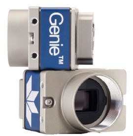
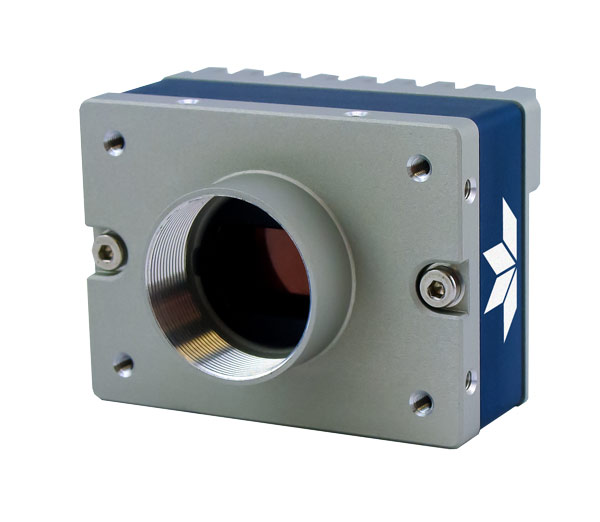
Image sensors are the key component of any camera and vision system.  This blog summarizes the key concepts of a tech brief addressing concepts essential to sensor performance relative to imaging applications. For a comprehensive analysis of the parameters, you may read the full tech brief.

Download Tech Brief - Choosing the Best Image Sensor

While there are many aspects to consider, here we outline 6 key parameters:

  1. Physical parameters


    Resolution: The amount of information per frame (image) is the product of horizontal pixel count x by vertical pixel count y.  While consumer cameras boast of resolution like car manufacturers tout horsepower, in machine vision one just needs enough resolution to solve the problem – but not more.  Too much resolution leads to more sensor than you need, more bandwidth than you need, and more cost than you need.  Takeaway: Match sensor resolution to optical resolution relative to the object(s) you must image.

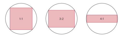
    Aspect ratio: Whether 1:1, 3:2, or some other ratio, the optimal arrangement should correspond to the layout of your target’s field of view, so as not to buy more resolution than is needed for your application.


    Frame rate: If your target is moving quickly, you’ll need enough images per second to “freeze” the motion and to keep up with the physical space you are imaging.  But as with resolution, one needs just enough speed to solve the problem, and no more, or you would over specify for a faster computer, cabling, etc.

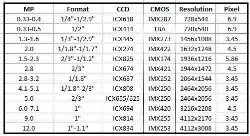
    Optical format: One could write a thesis on this topic, but the key takeaway is to match the lens’ projection of focused light onto the sensor’s array of pixels, to cover the sensor (and make use of its resolution).  Sensor sizes and lens sizes often have legacy names left over from TV standards now decades old, so we’ll skip the details in this blog but invite the reader to read the linked tech brief or speak with a sales engineer, to insure the best fit.

  2. Quantum Efficiency and Dynamic Range:


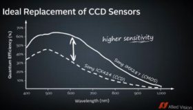
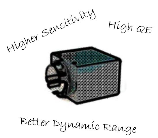
    Quantum Efficiency (QE): Sensors vary in their efficiency at converting photons to electrons, by sensor quality and at varying wavelengths of light, so some sensors are better for certain applications than others.

    Typical QE response curve

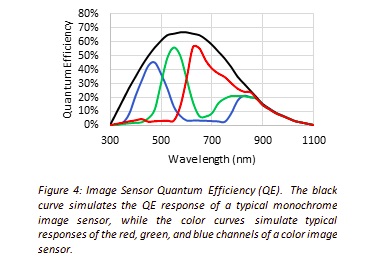
    Dynamic Range (DR): Factors such as Full Well Capacity and Read Noise determine DR, which is the ratio of maximum signal to the minimum.  The greater the DR, the better the sensor can capture the range of bright to dark gradations from the application scene.

  3. Optical parameters

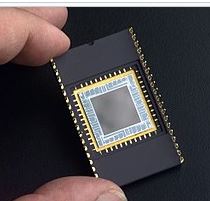
    While some seemingly-color applications can in fact be solved more easily and cost-effectively with monochrome, in either case each silicon-based pixel converts light (photons) into charge (electrons).  Each pixel well has a maximum volume of charge it can handle before saturating.  After each exposure, the degree of charge in a given pixel correlates to the amount of light that impinged on that pixel.

  4. Rolling vs. Global shutter

    Most current sensors support global shutter, where all pixel rows are exposed at once, eliminating motion-induced blur.  But the on-sensor electronics to achieve global shutter have certain costs associated, so for some applications it can still make sense to use rolling shutter sensors.

  5. Pixel Size

    Just as a wide-mouth bucket will catch more raindrops than a coffee cup, a larger physical pixel will admit more photons than a small one.  Generally speaking, large pixels are preferred.  But that requires the expense of more silicon to support the resolution for a desired x by y array.  Sensor manufacturers work to optimize this tradeoff with each new generation of sensors.

  6. Output modes

    While each sensor typically has a “standard” intended output, at full resolution, many sensors offer additional switchable outputs modes like Region of Interest (ROI), binning, or decimation.  Such modes typically read out a defined subset of the pixels, at a higher frame rate, which can allow the same sensor and camera to serve two or more purposes.  Example of binning would be a microscopy application whereby a binned image at high speed would be used to locate a target blob in a large field, then switch to full-resolution for a high-quality detail image.

For a more in depth review of these concepts, including helpful images and diagrams, please download the tech brief.

Download tech brief - Choosing the Best Image Sensor

1st Vision’s sales engineers have an average of 20 years experience to assist in your camera selection.  Representing the largest portfolio of industry leading brands in imaging components, we can help you design the optimal vision solution for your application.

What Are the Benefits of CMOS vs CCD Machine Vision Cameras?

Industrial machine vision cameras historically have used CCD image sensors, but there is a transition in the industrial imaging marketplace to move to CMOS imagers. Why is this?.. Sony who is the primary supplier of image sensors announced in 2015 it will stop making CCD image sensors and is already past its last time buy. The market was nervous at first until we experienced the new CMOS image sensor designs. The latest Sony Pregius Image sensors provide increased performance with lower cost making it compelling to make changes to systems using older CCD image sensors.

What is the difference between CCD and CMOS image sensors in machine vision cameras?

Both produce an image by taking light energy (photons) and convert them into an electrical charge, but the process is done very differently.

In CCD image sensors, each pixel collects light, but then is moved across the circuit via current through vertical and horizontal shift registers. The light level is then sampled in the read out circuitry. Essentially its a bucket brigade to move the pixel information around which takes time and power.

In CMOS sensors, each pixel has the read out circuitry located at the photosensitive site. The analog to digital circuit samples the information very quickly and eliminates artifacts such as smear and blooming. The pixel architecture has also radically changed moving the photosensitive electronics to be more efficient in collecting light.

6 advantages of CMOS image sensors vs CCD

There are many advantages of CMOS versus CCDs machine vision cameras outlined below:
1 – Higher Sensitivity due to the latest pixel architecture which is beneficial in lower light applications.
2 – Lower dark noise will contribute to a higher fidelity image.
3 – Pixel well depth (saturation capacity) is improved providing higher dynamic range.
4 – Lower Power consumption. This becomes important as lower heat dissipation equals a cooler camera and less noise.
5 – Lower cost! – 5 Megapixel cameras used to cost ~ $2500 and only achieve 15 fps and now cost ~ $450 with increased frame rates.
6 – Smaller pixels reduce the sensor format decreasing the lens cost.

Click to contact

What CMOS image sensors cross over from existing CCD image sensors?

1stVision can help in the transition starting with crossing over CCDs to CMOS using the following cross reference chart. Once identified, use the camera selector and select the sensor from the pull down menu.

Sony CCD to CMOS cross reference chart

1st Vision’s sales engineers have over 100 years of combined experience to assist in your camera selection.  With a large portfolio of lenses, cables, NIC card and industrial computers, we can provide a full vision solution!

Ph:  978-474-0044  /  info@1stvision.com  / www.1stvision.com

Related Blogs & Technical resources

What is the fastest 2.4MP GigE camera at the lowest price point? Dalsa’s new Nano M1950 / C1950!

Dalsa Nano

Dalsa NanoTeledyne Dalsa has released the latest addition to the Genie Nano family.  Introducing the Nano M1950 and C1950 cameras using the Sony Pregius IMX392 image sensor.  This is a great replacement for older Sony ICX818 CCD sensors.

These latest Nano models offer 2.4 MP (1936 x 1216) resolution with a GigE interface in color and monochrome with up to 102 frames per second utilizing TurboDrive.

What’s so interesting about the Nano M1950 and C1950 models?

2.4 MP resolution with the speed of the popular IMX174, but at the price of the IMX249:  
Sony Pregius image sensors in a given resolution has created paired sensors, one being faster at a higher price and one slower at a lower price.  The Nano M1940 / C1940 cameras use the IMX174 which is a great sensor and historically had the fastest speed at 2.4MP in GigE, but at a premium.  We could opt for the Nano M1920 / C1920 cameras with the IMX249 at a lower price, but sacrificed speed.

Until now! – The latest Nano M1950 / C1950 models with the IMX392 provides the higher speed of the M1940 / C1940 cameras, but at the lower price of the Nano M1920 / C1920 cameras. 

2.4MP resolution using a 1 /2 in sensor format, provides cost savings on lenses.
Thanks to the Sony Pregius Gen 2 pixel architecture, the pixel size is 3.45um, allowing the same resolution and eliminating the added cost of larger format lenses found in the IMX174 / IMX249 sensors which were 1 / 1.2″ formats.

Contact 1stVision to get our recommendations on lens series designed for the 3.45um pixel pitch. 

When would you use the Sony Pregius IMX392 versus the IMX174 and IMX249 sensors? 

The Sony Pregius IMX174 / IMX249 images still have an incredible dynamic range due to the pixel architecture found in the first generation image sensors.  (Read more here on Gen 1 vs Gen 2).  If you need dynamic range, with large well depths of 30Ke-, then use the IMX174 / IM249 sensors.

I’m so confused!   Where can I get the specs on the new Nano M1950 / C1950, understand what sensors are in what cameras and get a quote?

The tough part today, is that there a ton of model #’s in the Sony Pregius sensors lineup and in turn camera product lines.  Here’s a brief table to help with links to spec’s, related image sensors and a link to get a quote.

Sensor          Model 
IMX174         Nano M1940 / C1940          GET QUOTE
IMX249        Nano M1920 / C1920           GET QUOTE
IMX392        Nano M1950 / C1950           GET QUOTE

1st Vision’s sales engineers have over 100 years of combined experience to assist in your camera selection.  With a large portfolio of lenses, cables, NIC card and industrial computers, we can provide a full vision solution!

Contact us to help in the specification and providing pricing

Ph:  978-474-0044  /  info@1stvision.com  / www.1stvision.com

Related Blogs & Technical resources

Imaging Quick ref Poster
Quick Reference Imaging poster download

https://www.1stvision.com/machine-vision-solutions/2019/04/sony-pregius-3rd-generation-image-sensor.html

Teledyne Dalsa TurboDrive 2.0 breaks past GigE limits now with 6 levels of compression

What is a lens optical format? Can I use any machine vision camera with any format? NOT!

Learn about the new 5GigE camera interface

Dalsa Nano 5GigE

Machine vision interfaces have continued to evolve over the years increasing data throughput and cable lengths.  Commonly used interfaces are GigE and USB3.  However, 5GigE is an interface now gaining attention in the industrial imaging / machine vision market with some nice advantages.

We will outline the benefits of 5GigE, but first, lets give a brief overview of the commonly used camera interfaces, with their pluses and minuses:

GigE  / GigE Vision

  • 110 MB/s of sustainable throughput.  In real world terms, a HD, 2MP camera can get 50-55 fps in 8 bit mono or 8 bit color mode.  Note, this isn’t real HD, since you need 60 FPS.
  • Data cable lengths up to 100m using regular CAT 5e/6 cable.
  • Easy to put multiple cameras on a system.

USB 3 / USB3 Vision

  • 420 MB/s of data throughput.    A HD 2MP camera can run 60 fps in 8 bit mono or color and can  also run RGB at 60 FPS no problem.  With the higher throughput,  a 5MP camera can achieve 85 fps in 8 bit mode.
  • Data cables up to 5 meters and up to 20 meters with active cables. However, active cables can be quite costly, adding up to $200 in cost.
  • Not as easy as GigE to put multiple cameras on a system, and gets harder with each additional camera, especially if you have limited USB3 controllers.

As a note, there is no cost difference when using cameras with the same sensor from the same manufacturer with USB or GigE!  They will cost about the same with no premium for one interface over the other.

gige nano 5gigeWhat are the limitations of GigE and USB3 now solved by 5GigE?

  • USB3 is limited in cable length, so going faster than GigE is great, but you can not have long cable lengths.
  • GigE has cable lengths up to 100 meters, but is limited to ~ 110MB/s of data, so you do not have the high frame rates as in a USB3 camera.
  • USB3 in 4+ camera systems is not as stable as GigE AND you’re still limited on cable lengths.

Wait! – What about 10GigE? 

Up until now, 10G was the next interface. However, the jump to 10G has quite a few limitations as outlined below.

  • Heat generation is significant, so cameras are large and not in the smaller 29 x 29mm cube form factor.
  • Not a lot of demand for very high speed 10G, so not a lot of sensors being offered
  • Minimal number of manufacturers for 10G, higher cost.
  • Special cabling, either optical or high quality cat 7.

What we have found is that there are several types of applications for 10G cameras and are as follows

  • Applications where you need 10G of speed of course (high resolution + fast frame rates)
  • Require greater than  110MB/s of data and need long cable lengths.
  • Where there is the required combination of 110MB/s for high frame rates, multiple cameras and long cable lengths, 10G is a perfect solution.

We have seen that the need for higher bandwidth + long cable lengths is more prominent vs. the real need for 10GigE!

 Introducing 5GigE that provides increased bandwidth, long cable lengths at reasonable prices! or N Base T.5GigE machine vision applications

5GigE (also known as N Base T) has become a new standard for industrial, machine vision cameras.

In the general compute world, a much much larger market than vision, there has also been a need to go faster than GigE. However, the issue of replacing the existing cabling is the major issue preventing this. If you think of a big box store, say a Home Depot for instance, the amount of cabling is huge. Ripping that out and rewiring far exceeds the cost of the equipment to use it!

5G was made to go faster, but use existing cabling. Regular cat6e cable can be used, and 5G is a subset of 10G, so all switches etc. can be kept in service.

5G gives users in the vision market USB3 speeds, but with ALL of the regular GigE features, at a very small premium!

get quote1st Vision’s sales engineers have over 100 years of combined experience to assist in your camera selection.  With a large portfolio of lenses, cables, NIC card and industrial computers, we can provide a full vision solution!