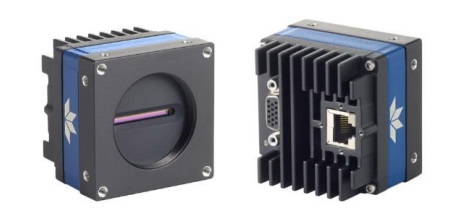
The new Linea2 4k color camera with a 5GigE interface delivers RGB images at a max line rate of 42kHz x3. That’s 5x the bandwidth of the popular Linea 1 GigE cameras.
Linea2 4k color cameras with 5GigE – courtesy Teledyne Dalsa
Perhaps you already use the Linea GigE cameras, at 1 GigE, and seek an upgrade path to higher performance in an existing application. Or you may have a new application for which Linea2 performance is the right fit. Either way, Linea2 builds on the foundation of Teledyne DALSA’s Linea family.
Why line scan?
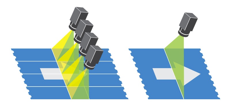
While area scan is the right fit for certain applications, compare area scan to line scan for the hypothetical application illustrated below:
Area scan vs. Line scan – courtesy Teledyne DALSA
If one were to implement an area scan solution, you’d need multiple cameras to cover the field of view (FOV). Plus you’d have to manage lighting and framerate to avoid smear and frame overlaps. With line scan, one gets high resolution without smear, and a single camera solution – ideal to inspect a moving surface.
Call us at 978-474-0044 to tell us about your application, and we can guide you to a suitable line scan or area scan camera for your solution. Of course we also have the right lenses, lighting, and other components.
Sensor
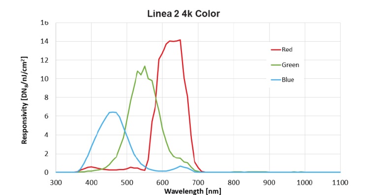
The Trilinear CMOS line scan sensor is Teledyne’s own 4k color design, with outstanding spectral responsivity as shown below:
Linea2 Color responsivity – courtesy Teledyne DALSA
The integrated IR-cut filters insure true-color response is delivered on the native RGB data outputs.
Interface
With a 5GigE Vision interface, the Linea2 provides 5x the bandwidth of the conventional GigE interface, but can use the same Cat5e or Cat6 network cables – and does not require a frame grabber.
Software
Sapera LT software development kit is recommended, featuring:
Intuitive CamExpert graphical user interface for configuration and setup
Trigger-To-Image Reliability tool (T2IR) for system monitoring
Sapera LT has over 500,000 installations worldwide. Thanks to the 5GigE Vision interface, popular third party software is of course also compatible.
Applications
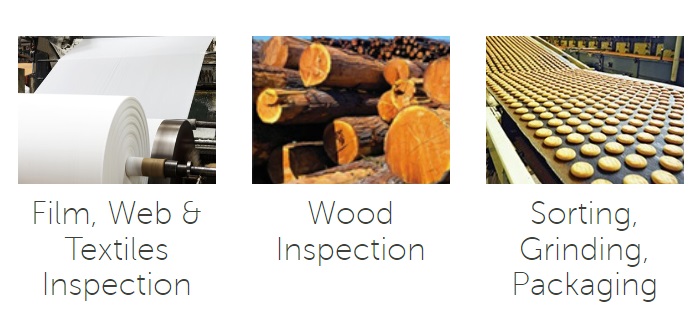
Application examples – courtesy Teledyne DALSA
While not limited to those listed below, known and suggested uses include:
Printing inspection
Web inspection
Food, recycling, and material sorting
Printed circuit board inspection
Web inspection
etc.
Call us at 978-474-0044. Or follow the contact us link below to provide your information, and we’ll call you.
Webcams aren’t (yet) found in Cracker Jack boxes, but they are very inexpensive. And they seem to perform ok for Zoom meetings or rendering a decent image of an office interior. So why not just use a webcam as the front end for a machine vision application?
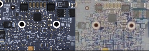
Before we dig in to analysis and rationale, let’s motivate with the following side-by-side images of the same printed circuit board (PCB):
Machine vision camera and lens vs. webcam – Courtesy 1stVision
Side-by-side images
In the image pair above, the left image was generated with a 20MP machine vision camera and a high resolution lens. The right image used a webcam with a consumer sensor and optics.
Both were used under identical lighting, and optimally positioned within their specified operating conditions, etc. In other words we tried to give the webcam a fair chance.
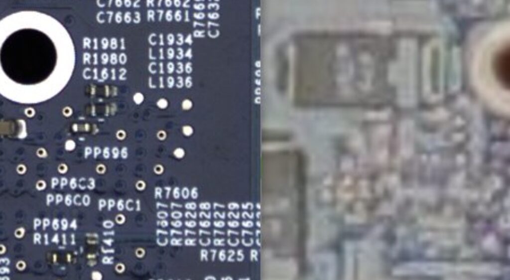
Even in the above image, the left image looks crisp with good contrast, while the right image has poor contrast – that’s clear even at a wide field of view (FOV). But let’s zoom in:
Clearly readable labeling and contact points (left) vs. poor contrast and fuzzy edges (right)
Which image would you prefer to pass to your machine vision software for processing? Exactly.
Machine vision cameras with lens mounts that accept lenses for different applications
Why is there such a big difference in performance
We’re all so used to smartphones that take (seemingly) good images, and webcams that support our Zoom and Teams meetings, that we may have developed a bias towards thinking cameras have become both inexpensive and really good. It’s true that all cameras continue to trend less expensive over time, per megapixel delivered – just as with Moore’s law in computing power.
As for the seemingly-good perception, if the images above haven’t convinced you, it’s important to note that:
Most webcam and smartphone images are wide angle large field of view (FOV)
Firmware algorithms may smooth values among adjacent pixels to render “pleasing” images or speed up performance
Most machine vision applications, on the other hand, demand precise details – so firmware-smoothed regions may look nice on a Zoom call but could totally miss the defect-discovery which might be the goal of your application!
Software
Finally, software (or the lack thereof) is at least as important as image quality due to lens and sensor considerations. With a webcam, one just gets an image burped out, but nothing more.
Conversely, with a machine vision camera, not only is the camera image better, but one gets a software development kit (SDK). With the SDK, one can:
Configure the camera’s parameters relative to bandwidth and choice of image format, to manage performance requirements
Choose between streaming vs. triggering exposures (via hardware or software trigger) – trigger allows synchronizing to real world events or mechanisms such as conveyor belt movement, for example
Access to machine vision library functions such as edge detection, blob analysis, occlusion detection, and other sophisticated image analysis software
Proprietary SDKs vs. 3rd party SDKs
Speaking of SDKs, the camera manufacturers’ are often very powerful and user friendly. Just to name a few, Teledyne Dalsa offer Sapera, Allied Vision provides Vimba, and IDS Imaging supports both IDS Lighthouse and IDS Peak.
Compare to Apple or Microsoft in the computing sector – they provide bundled software like Safari and Edge, respectively. They work hard on interoperability of their laptops, tablets, and smartphones, to make it attractive for users to see benefits from staying within a specific manufacturer’s product families. Machine vision camera companies do the same thing – and many users like those benefits.
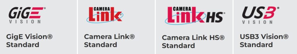
Vision standards – Courtesy Association for Advancing Automation,
Some users prefer 3rd party SDKs that help maintain independence to choose cameras best-suited to a given task. Thanks to machine vision industry standards like GigE Vision, USB3 Vision, Camera Link, GenICam, etc., 3rd party SDKs like MATLAB, OpenCV, Halcon, Labview, and CVB provide powerful functionality that are vendor-neutral relative to the camera manufacturer.
For a deeper dive into machine vision cameras vs. webcams, including the benefits of lens selection, exposure controls, and design-in availability over time, see our article: “Why shouldn’t I buy a $69 webcam for my machine vision application?” Or just call us at 978-474-0044.
In summary, yes a webcam is a camera. For a sufficiently “coarse” area scan application, such as presence/absence detection at low resolution – a webcam might be good enough. Otherwise note that machine vision cameras – like most electronics – are declining in price over time for a given resolution, and the performance benefits – including software controls – are very compelling.
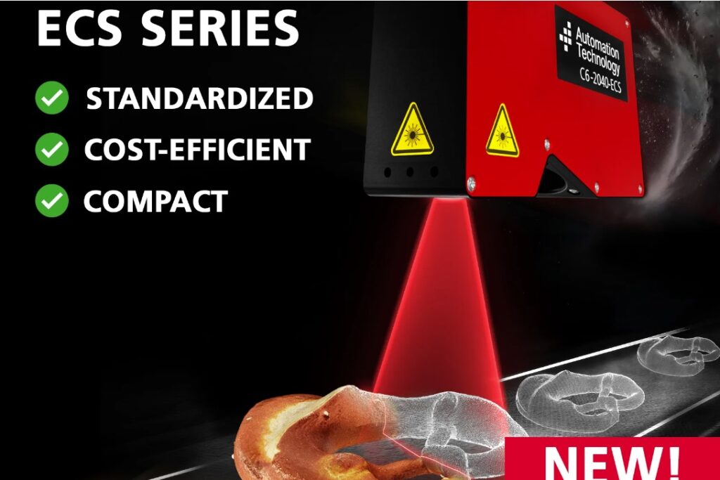
AT Sensors – previously known as Automation Technology – announces the ECS series, where ECS means Eco Compact Sensor. Using less expensive optics and sensors, the standardized pre-configured offering is more than good enough for many applications. And priced to pass the lower-cost component savings on to the customer.
ECS 3D sensors – Courtesy AT Sensors
Ideal for applications in food, logistics, and robot vision, the sweet spot is performance that’s good enough to add value and get the job done, without having to purchase components needed for even higher performance. ECS sensors use the principle of laser triangulation to create a 3D point cloud.
Resolution and speed.
ECS delivers 2048 points per profile, at up to 43 kHz. Compare that to AT’s higher end scanners with up to 4096 points per profile, and speeds to 204 kHz.
Field of View (FoV)
Initial ECS series members are offered at 100 or 160mm FoVs, with other options planned for release.
Compact design
At only 0.65kg, about 1lb in weight, ECS 3D compact sensors can be easily integrated into many applications.
Software integration
AT Sensors AT Solution package makes it easy to configure your sensor. The SDK provides options for C, C++, and Python. The GigE Vision / GenICam interface means users may also choose any software compliant with those popular industry standards.
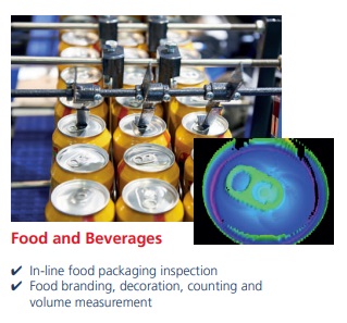
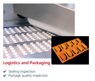
Applications
As mentioned above, food/beverage, logistics, packaging, and robotics are just a few of the suggested application areas.
Images above courtesy of AT Sensors
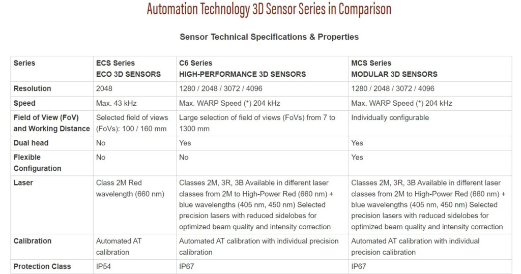
Three 3D sensor families: Value, Performance, and Modular
To put it in perspective, AT Sensors has expanded its 3D sensor portfolio with price : performance offerings at each of:
Performance: C6 Series – high-performance, pre-configured, IP67 protection, mid-priced
Modular: MCS Series – high-performance flexible configuration, IP67 protection
Comparing 3D Sensor Series – Courtesy Automation Technology GmbH
See an expanded comparison table at our website. But at a high level think of ECS as the value series. The C6 models offer high performance at a choice of resolutions. And the MCS is a modular unbundling of the C6 products – high-performance with flexible configuration.
What matters to you of course is your own application. And that’s what matters to us, too. As an independent distributor, we work for you. Tell us about your application, and we’ll guide to to the best-fit technology for your needs. Call us at 978-474-0044.
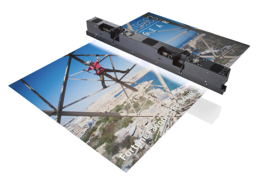
Teledyne DALSA has released the AxCIS 800mm mono/HDR, and the AxCIS 400mm mono, the first two members of a new flexible and scalable product family of Contact Image Sensors (CIS). As other members are released, users can choose fields of view (FoV) in 100mm increments, e.g. 400mm, 500mm, 600mm, 700mm, and 800mm.
AxCIS 800mm lighting and scanning – Courtesy Teledyne DALSA
Actually that’s a trick heading! A contact image sensor (CIS) is a type of linescan camera. Conventionally, the industry calls it a linescan camera if the sensor uses CMOS or CCD. while it’s called a CIS if it bundles a linear array of detectors, lenses, and lights.
But CIS is very much a linescan type of camera, With a 2D area scan camera, a comprehensive pixel array captures hundreds or thousands of (X,Y) values in a single exposure. But a Contact Image Sensor requires either the target or the imaging unit to move, as a single exposure is a slice of Y values at a given coordinate X. Motion is required to step across the set of X values.
Two more notes:
The set of X values may be effectively infinite, as with “web inspection” applications
The term “contact” in CIS is a bit of a misnomer. The sensor array is in fact “very close” to the surface, which must thereby be essentially flat in order to sustain collision-free motion. But it doesn’t actually touch.
AxCIS key attributes include:
28um pixel size (900dpi)
high speed 120KHz using Camera Link HS
HDR imaging with dual exposure mode
optional LED lighting
fiberoptic cables immune to EMI radiation
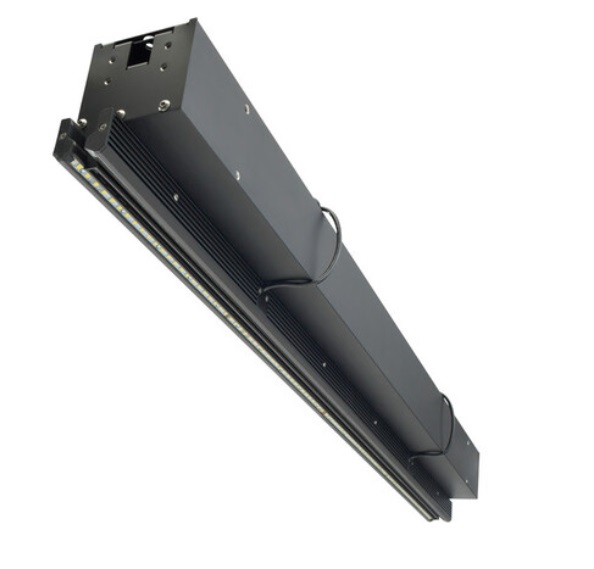
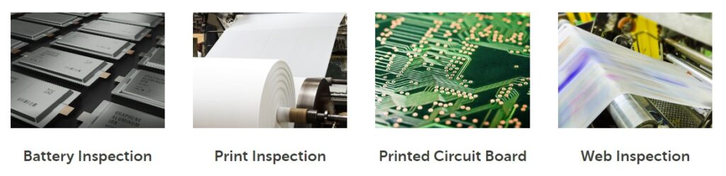
Application areas share the characteristics of flat surfaces and motion of either the target or the sensor, since contact image sensing (CIS) is a form of linescan imaging.
Courtesy Teledyne DALSA
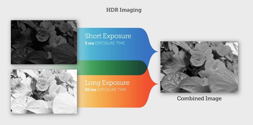
HDR imaging
Some targets are inherently challenging to obtain sufficient saturation for the darker regions while avoiding over-saturation for the lighter areas. The multiline sensors used in AxCIS utilize a sensor array with:
One row of the sensor array that can have a longer exposure for dark scenes
Another row using a shorter exposure for light scenes
The camera then combines the images, as shown below. The technique is referred to as High Dynamic Range imaging – HDR.
Ilustration of HDR Imaging – Courtesy Teledyne DALSA
Want to know more about area scan vs line scan? And multifield line scan? And other Teledyne DALSA linescan products, in which they have years of expertise? See our blog “What can multifield linescan imaging do for me?“.
For details on the AxCIS CIS family, please see the product page with detailed specs.
If you’ve had enough reading, and want to speak with a real live engineer, just call us at 978-474-0044.