“A line scan system is only as good as its weakest component”
Granted, any system is only as good as its weakest component. But with some systems one can cut corners here or there and get away with it. With line scan mostly not. But the rewards of getting it right can deliver effective applications with excellent return on investment.
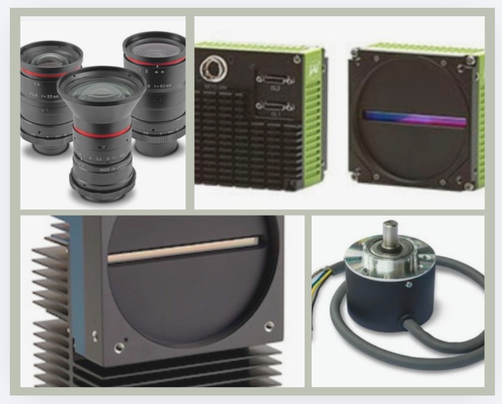
Success depends upon balancing all of the following:
- Camera
- Lens
- Lighting
- Motion system
- Encoder
- Mechanical stability
- Image processing
Below we’ll look at each of these in turn.
Camera (and the sensor it contains)
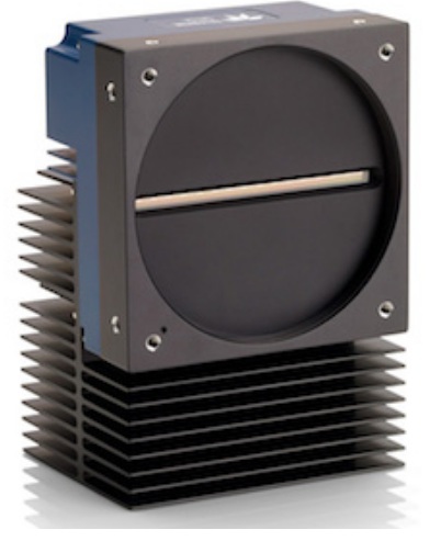
One selects a line scan camera containing typically “one narrow row” of pixels. The row’s length is chosen to correspond to the width of the thing you are inspecting. The other dimension for the 2D application comes via the motion of the object past the camera – or vice versa.
Left: A representative line scan camera – Courtesy Teledyne DALSA
The “narrow row” may be 1, 2, or sometimes 3 or 4 pixels deep. A single pixel row offers the lowest cost, and can be sufficient for some applications. Adding a second or third pixel row, typically offset or staggered with respect to the adjacent row, offers improved resolution.
Line scan cameras may be monochrome or color in the visible (VIS) range. Or SWIR in the infrared portion of the spectrum. Or blended VIS-SWIR.
Right: Representative line scan camera front and back sides – Courtesy JAI.
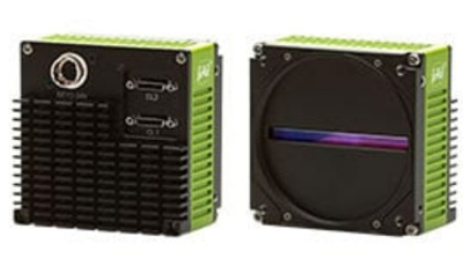
There are several tens of line scan cameras from which to choose.
Lens
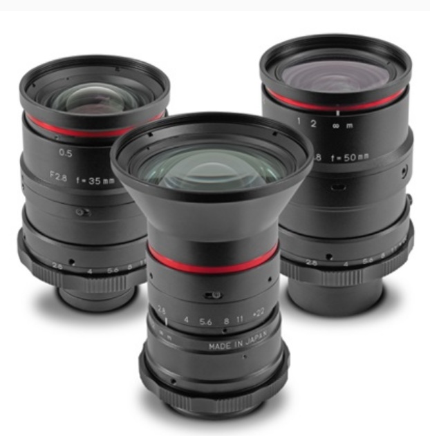
The lens focuses the target object onto your camera’s sensor, so the photons are captured in the pixel well and digitized for subsequent interpretation. Don’t cut corners on the lens.
Lighting
Successful image processing depends on sufficient contrast to differentiate amongst details. While the sensor and the lens are critical, so too is lighting. In fact good lighting can sometimes permit using a “lesser” sensor or lens. Or achieving ambitious outcomes otherwise not possible without attention to lighting.
See our Knowledge Base Techbriefs on lighting. Each may be downloaded for free.
Motion system
As noted above in the camera segment, the other dimension for the 2D application comes via the motion of the object past the camera – or vice versa. This is the key aspect of line scan systems – there’s a never ending dimension in the direction of motion, and each image is a time-slice from that continuous movement.
One can move the “product” along a conveyer belt, “web” of spooled paper, etc., while holding the line scan camera and lighting fixed. Or one can move the line scan camera across the product, as with a flatbed scanner.
Ideally the motion should be continuous speed – or if variable use an encoder (see below). Capable of long use without a lot of frequent re-calibration beyond scheduled service maintenance. And with little variability in the third dimension – unless of course your application is a blend of line scan and height profiling, such as laser profiling.
Encoder
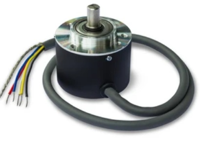
For variable speed product motion, e.g. conveyor belt with non-uniform speed during imaging, an encoder converts the rotary motion of a gear or transport wheel into electrical signals correlated to the speed of rotation.
Those signals can drive the shutter trigger on the camera.
Image royalty free – Courtesy Shutterstock.
Bonus blurb – calculating line rate
Related to how to make the whole system come together… and certainly tied to the motion system and encoder segments above, see our blog from some months ago on how to calculate line rate based on conveyor speed. That blog includes a downloadable spreadsheet with labeled fields and examples… and embedded formulas.
Mechanical stability
There’s no obvious graphic to show for this one, but one doesn’t have to be a mechanical or an optical engineer to get the point. Unplanned motion is highly undesirable, as all those lens and sensor choices are based upon a stable environment.
Sure, motion in one dimension is a given with line scan, but fast shutter takes care of that. But “wiggle” in the dimension of the pixel line, or height variability of the product being inspected – or of the line scan camera itself, introduce blur and uncertainty. Or the need to compensate for it.
Image processing
Machine vision is all about letting software interpret the image, adding value through speed, accuracy, tirelessness, and consistency. From camera configuration and control through image processing, you have a range of options.
There are camera manufacturer SDKs, third party software, and open source choices. And OS options including Windows, Linux, and various embedded systems platforms.

1st Vision’s sales engineers have over 100 years of combined experience to assist in your camera and components selection. With a large portfolio of cameras, lenses, cables, NIC cards and industrial computers, we can provide a full vision solution!
About you: We want to hear from you! We’ve built our brand on our know-how and like to educate the marketplace on imaging technology topics… What would you like to hear about?… Drop a line to info@1stvision.com with what topics you’d like to know more about.
#linescan