Considerations in using an F-mount vs. a threaded mount

For machine vision purposes, we generally advise against using F-mount. We don’t have a dog in the hunt for leisure or artistic photography, but for reliability in many machine vision applications there are shortcomings with F-mounts.

EMERALD series F-mount lens – Courtesy Schneider Optics

Even our premier partner Schneider Optics, produces very fine F-mount lenses – the optics are first class! But just as a reliable auto dealership would counsel against buying a compact sedan to tow a heavy boat, we would hope to engage you in dialogue about your imaging application – and help you choose the best lens.

Contact us

There are many lens mounts available

The wide range of lens mounts is, generally speaking, a very good thing. It permits camera designers and manufacturers to specialize in what they are good at; and likewise for lens designers and their own production facilities. The former is electronics while the latter is about optics.

By defining standards for lens mounts, we all benefit from market competition, which drives quality, feature, and price differentiation.

Some mounts are for large-format sensors. Some for small sensors. Some for “quick change”. Some for stability. Some can fit several niches. Some can in theory but shouldn’t be pushed in practice. Below we provide examples.

Lens families from a single manufacturer by sensor size and pixel size – Courtesy Schneider Optics

What should we consider with F-mounts?

If you are a sports photographer, F-mount may be an excellent choice. The bayonet mount design is ideal for quick lens changes, and the “money shot” may require a quick lens swap. If shooting at really short exposure times, inherent instability in the mount design may not have an impact on image quality.

While the F-mount name traces to the famous Nikon F camera series, one might also think of it as for “Fotographie” – the German work for photography – if you like mnemonic hints.

But for machine vision applications, one typically mates the lens to the camera “forever”, so quick-change benefits are of little value. And compared to screw mounts, for example, it’s clear that the bayonet mount, with just two securing points, might suffer in a high-vibration environment. Whether on the factory floor, a traffic camera gantry, or a moving vehicle, the lens and camera should act as one. Stability is key.

For the record, F-mount defines a standard Flange Distance of 46.5mm from the mounting surface of the camera to the sensor, as well as standardized mechanics on the size and position of the male pins on the lens and the female receptors on the camera body. For those cameras or lenses with electrical contacts as well, there are variances. But mechanically and optically and F-mount is an F-mount.

What about the M42 lens mount?

While the M42 lens mount came into existence for “photography”, when computers and then machine vision emerged, M42 has become one of many popular lens mounts. The threaded screw mount design provides a very secure connection that binds along several turns of the screw – so it’s very resistant to vibration.

But while the conceptual design is great, M42 isn’t really a “full standard” in two important ways…

M42 doesn’t define flange distance

Every lens must precisely focus light rays onto the sensor surface. Camera makers position sensors a precise distance from the shoulder of the mount, a distance referred to as the flange distance, or flange focal distance. Curiously, there isn’t universal agreement on what that distance should be – though there is some convergence on a couple of de facto conventions.

The M42 lenses may need to have an extension tube added so that they can image on a camera sensor. Thankfully an extension tube is an inexpensive but effective accessory – but it’s important to note focal distances and source components accordingly.

M42 doesn’t define thread pitch

The second caveat with M42 mounts is that there are at least two common thread pitches offered: both 0.75 and 1.0.

Annotated snapshot of 1stVision lens selector tool.

If we use the 1stVision lens-selector, the Lens Mount dropdown shows both M42x0.75 as well as M42x1 options (as well as many other lens mounts). So if you know the camera mount specifications, you can find lenses that will thread correctly – but one needs to pay attention!

All the mounts we offer

To the left is a snapshot from the 1stVision lens-selector, showing the dropdown for all lens mounts we offer. If one chooses “All” it yields some 200 lenses across more than 10 manufacturers.

By specifying the lens mount, for the camera you are considering, one need only select a couple of additional dropdowns like sensor format, and focal length, to home in on candidate lenses for your application.

Each mount has its role. While a camera designer sometimes has options relative to sensor size, intended market, and price : performance decisions, there are good reasons why each mount type exists. And while some cameras are available with two or more mount options, generally speaking the camera you choose will dictate the mount – and hence the lens options.

Don’t fixate on the mount

While we’ve discussed certain aspect of lens mounts in this blog, you can generally trust that camera designers have chosen a suitable one for any particular camera – after all they want to maximize the number of cameras they can sell. There are many other considerations in machine vision lens selection. You can read all about it, or just…

1st Vision’s sales engineers have over 100 years of combined experience to assist in your camera and components selection.  With a large portfolio of cameraslensescablesNIC cards and industrial computers, we can provide a full vision solution!

About you: We want to hear from you!  We’ve built our brand on our know-how and like to educate the marketplace on imaging technology topics…  What would you like to hear about?… Drop a line to info@1stvision.com with what topics you’d like to know more about

Teledyne DALSA AxCIS Contact Image Sensor Applications

Why read this blog?

  1. To learn what kinds of applications are well-suited for a Contact Image Sensor
  2. To see the unique features only found in the Teledyne DALSA AxCIS series

You already know (or can catch up quickly):

Contact Image Sensors don’t actually contact the things they are imaging. But they get to within 15 mm = 0.59 inches! So they are ideal for space-constrained applications.

And they aren’t interchangeable with line scan cameras, they are a variant on line scan concepts. They share the requirement that “something is moving” and that the sensor array is a single row of pixels.

contact us

Applications for Contact Image Sensing

Courtesy Teledyne DALSA

Why Teledyne DALSA AxCIS in particular?

You may want to review the whole Teledyne DALSA AxCIS series, and the datasheet details. Go for it! Geek out. Full transparency as always.

Or maybe you’d like a little help on what we think is special about the Teledyne DALSA AxCIS series?

T2IR – Trigger to Image Reliability

This is a Teledyne DALSA proprietary innovation that helps to de-mystify what’s happening inside a complex vision system. It uses hardware and software to improve reliability. In high level terms, T2IR monitors from trigger through image capture, and on to host memory transfer, aiming to protect against data loss. And to provide insights for system tuning if needed. T2IR is compatible with many Teledyne DALSA cameras and frame grabbers – including the AxCIS series.

Courtesy Teledyne DALSA

If you prefer it written out:

Courtesy Teledyne DALSA

1st Vision’s sales engineers have over 100 years of combined experience to assist in your camera and components selection.  With a large portfolio of cameraslensescablesNIC cards and industrial computers, we can provide a full vision solution!

About you: We want to hear from you!  We’ve built our brand on our know-how and like to educate the marketplace on imaging technology topics…  What would you like to hear about?… Drop a line to info@1stvision.com with what topics you’d like to know more about

How to calculate line rate on a line scan camera based on conveyor speed

Unless one calculates and sets the line rate correctly, there’s a risk of blur and sub-optimal performance. And/or purchasing a line scan camera that’s not up to the task; or that’s overkill and costs you more than would have been needed.

Line Scan concept – Courtesy Teledyne DALSA

Optional line scan review or introduction

Skip to the next section if you know line scan concepts already. Otherwise…

Perhaps you know about area scan imaging, where a 2D image is generated with a global shutter, exposing all pixels on a 2D sensor concurrently. And you’d like to understand line scan imaging by way of comparing it to area scan. See our blog What is the difference between an Area Scan and a Line Scan Camera?

30 minute informative overview of Line Scan imaging – Courtesy Teledyne DALSA

Maybe you prefer seeing a specific high-end product overview and application suggestions, such as the Teledyne DALSA 16k TDI line scan camera with 1MHz line rate. Or a view to tens of different line scan models, varying not only by manufacturer, but by sensor size and resolution, interface, and whether monochrome or color.

Either you recall how to determine resolution requirements in terms of pixel size relative to defect size, or you’ve chased the link in this sentence for a tutorial. So we’ll keep this blog as simple as possible, dealing with line rate calculation only.

Line scan cameras – Courtesy Teledyne DALSA

Calculate the line rate

Getting the line rate right is the application of the Goldilocks principle to line scanning.

Line rate too slow…Line rate too fast…
Blurred image if due to too long exposure, and/or missed segments due to skipped “slices”Oversampling can create confusion by identifying the same feature as two distinct features
Why we need to get the line rate rate right

A rotary encoder is typically used to synchronize the motion of the conveyor or web with the line scan camera (and lighting if pulsed). Naturally the system cannot be operated faster than the maximum line speed, but it may sometimes operator more slowly. This may happen during ramp up or slow down phases – when one may still need to obtain imaging – or by operator choice to conserve energy or avoid stressing mechanical systems.

Naming the variables … with example values

Resolution A = object space correlation to sensor; FOV / pixel array; e.g. if 550mm FOV and 2k sensor = 550/2000 = 0.275 pixels per mm

Transport speed T = mm per sec; e.g. 4k / 1mm yields rate of motion

Sampling frequency F = T / A; for example values above F = 4000 / 0.275 = 14545.4545 = 14.5kHz; spelled out: Frequency = Transport_speed / Pixel_spatial_resolution (what 1 pixel equals in target space)

For the example figures used above, a line scan camera with 2k resolution and a line scan frequency of about 14.5 kHz will be sufficient.

Download spreadsheet with labeled fields and examples:

Just click here, or on the image below, to download the spreadsheet calculator. It includes clearly labeled fields, and examples, as the companion piece for this blog:

Not included here… but happy to show you how

We’ve kept this blog intentionally lean, to avoid information overload. Additional values may also be calculated, of course, such as:

Data rate in MB / sec: Useful to confirm camera interface can sustain the data rate

Frame time: The amount of time to process each scanned image. Important to be sure the PC and image processing software are up to the task – based on empirical experience or by conferring with software provider.

1st Vision’s sales engineers have over 100 years of combined experience to assist in your camera and components selection.  With a large portfolio of cameraslensescablesNIC cards and industrial computers, we can provide a full vision solution!

About you: We want to hear from you!  We’ve built our brand on our know-how and like to educate the marketplace on imaging technology topics…  What would you like to hear about?… Drop a line to info@1stvision.com with what topics you’d like to know more about

Moritex ML-M-HR 2/3″ Format Lenses

Superior vibration resistance and mechanical design

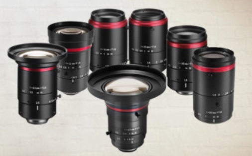
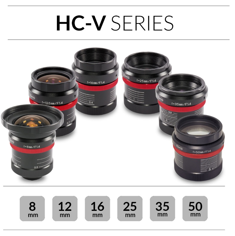
Two of six available ML-M-HR lens models – Courtesy Moritex

Value Engineering

Every field with diverse product offerings has its own broad mix from which to choose. Some offerings are generalized; some fit a specific niche. When designing a machine vision application, and choosing components like cameras, sensors, lenses, lighting, etc., each component has to be at least slightly better than “good enough”, but need not be more than needed. The whole field of value engineering has evolved to guide practitioners in achieving required functionality while also respecting budgetary goals.

Larger FA series design goals which ML-M-HR series share- Courtesy Moritex

Moritex ML-M-HR lens series

The Moritex ML-M-HR series is part of Moritex larger FA Series of lenses. The “FA” stands for Factory Automation, which suggests points including:

  • Robust mechanical engineering
  • Quality designed to deliver reliable results and stand the test of time
  • Priced to permit volume purchases by achieving return on investment

Of course, the lenses are not constrained to factory automation, and you may purchase as few as you need. The factory automation insight just helps to understand their design heritage and largest market.

Contact us for a quote

Specifics:

Key attributes of the Moritex ML-M-HR lens series

Pixel size and resolving capacity

Designed for 4.5 µm pixels, the lenses may of course also be used with larger pixels, but aren’t suitable for smaller. So they are an ideal fit for Sony Pregius 3rd generation sensors.

See Moritex lens families for other pixel sizes and lens types. The Moritex ML-M-HR lenses resolve to 130 line pairs / mm. See our Knowledge Base article Key Considerations in Machine Vision Lens Selection for generalized guidance on concepts.

With wide-range anti-reflective (AR) coatings, the lenses provide consistent transmission from visible (Vis) through near infrared (NIR) wavelengths, i.e. 400 ~ 1100nm.

Six member family

There are six choices in the Moritex ML-M-HR series, spanning from focal lengths 8mm – 50mm, at typical intervals. The link in the previous sentence takes you to the detailed table – and quote request buttons.

Robotics application is just an example – Courtesy Moritex

1st Vision’s sales engineers have over 100 years of combined experience to assist in your camera and components selection.  With a large portfolio of cameraslensescablesNIC cards and industrial computers, we can provide a full vision solution!

About you: We want to hear from you!  We’ve built our brand on our know-how and like to educate the marketplace on imaging technology topics…  What would you like to hear about?… Drop a line to info@1stvision.com with what topics you’d like to know more about