How to calculate line rate on a line scan camera based on conveyor speed

Unless one calculates and sets the line rate correctly, there’s a risk of blur and sub-optimal performance. And/or purchasing a line scan camera that’s not up to the task; or that’s overkill and costs you more than would have been needed.
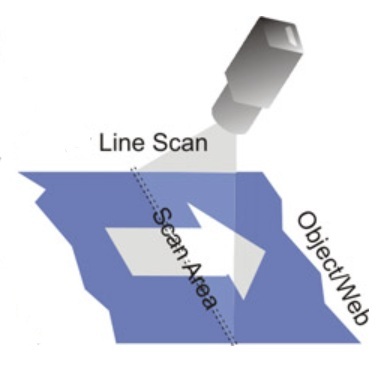
Line Scan concept – Courtesy Teledyne DALSA

Optional line scan review or introduction

Skip to the next section if you know line scan concepts already. Otherwise…

Perhaps you know about area scan imaging, where a 2D image is generated with a global shutter, exposing all pixels on a 2D sensor concurrently. And you’d like to understand line scan imaging by way of comparing it to area scan. See our blog What is the difference between an Area Scan and a Line Scan Camera?

30 minute informative overview of Line Scan imaging – Courtesy Teledyne DALSA

Maybe you prefer seeing a specific high-end product overview and application suggestions, such as the Teledyne DALSA 16k TDI line scan camera with 1MHz line rate. Or a view to tens of different line scan models, varying not only by manufacturer, but by sensor size and resolution, interface, and whether monochrome or color.

Either you recall how to determine resolution requirements in terms of pixel size relative to defect size, or you’ve chased the link in this sentence for a tutorial. So we’ll keep this blog as simple as possible, dealing with line rate calculation only.
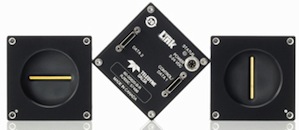
Line scan cameras – Courtesy Teledyne DALSA

Calculate the line rate

Getting the line rate right is the application of the Goldilocks principle to line scanning.

Line rate too slow…Line rate too fast…
Blurred image if due to too long exposure, and/or missed segments due to skipped “slices”Oversampling can create confusion by identifying the same feature as two distinct features
Why we need to get the line rate rate right

A rotary encoder is typically used to synchronize the motion of the conveyor or web with the line scan camera (and lighting if pulsed). Naturally the system cannot be operated faster than the maximum line speed, but it may sometimes operator more slowly. This may happen during ramp up or slow down phases – when one may still need to obtain imaging – or by operator choice to conserve energy or avoid stressing mechanical systems.

Naming the variables … with example values

Resolution A = object space correlation to sensor; FOV / pixel array; e.g. if 550mm FOV and 2k sensor = 550/2000 = 0.275 pixels per mm

Transport speed T = mm per sec; e.g. 4k / 1mm yields rate of motion

Sampling frequency F = T / A; for example values above F = 4000 / 0.275 = 14545.4545 = 14.5kHz; spelled out: Frequency = Transport_speed / Pixel_spatial_resolution (what 1 pixel equals in target space)

For the example figures used above, a line scan camera with 2k resolution and a line scan frequency of about 14.5 kHz will be sufficient.

Download spreadsheet with labeled fields and examples:

Just click here, or on the image below, to download the spreadsheet calculator. It includes clearly labeled fields, and examples, as the companion piece for this blog:
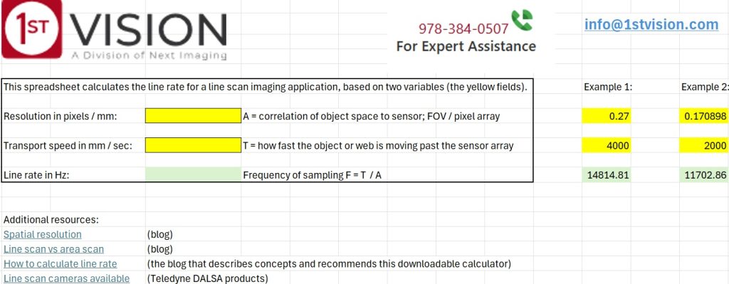
Not included here… but happy to show you how

We’ve kept this blog intentionally lean, to avoid information overload. Additional values may also be calculated, of course, such as:

Data rate in MB / sec: Useful to confirm camera interface can sustain the data rate

Frame time: The amount of time to process each scanned image. Important to be sure the PC and image processing software are up to the task – based on empirical experience or by conferring with software provider.

1st Vision’s sales engineers have over 100 years of combined experience to assist in your camera and components selection.  With a large portfolio of cameras, lenses, cables, NIC cards and industrial computers, we can provide a full vision solution!

About you: We want to hear from you!  We’ve built our brand on our know-how and like to educate the marketplace on imaging technology topics…  What would you like to hear about?… Drop a line to info@1stvision.com with what topics you’d like to know more about
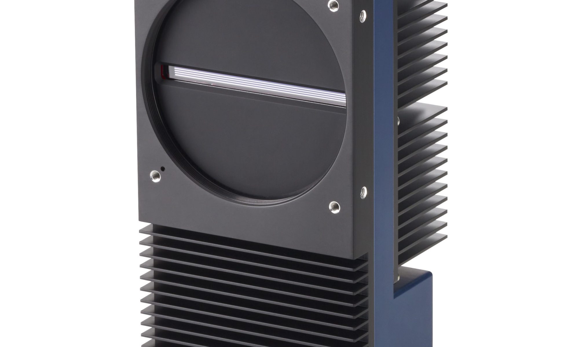
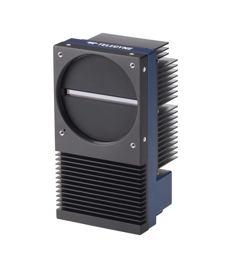
Teledyne DALSA 16k TDI line scan camera 1 MHz line rate

Product innovation continues to serve machine vision customers well. Clever designs are built for evolving customer demands and new markets, supported by electronics miniaturization and speed. Long a market leader in line scan imaging, Teledyne DALSA now offers the Linea HS2 TDI line scan camera family.

Linea HS2 16k TDI line scan camera with 1 MHz line rate – courtesy Teledyne DALSA

Video overview

The video below is just over one minute in duration, and provides a nice overview:

Contact us for a quote

Backside illumination enhances quantum efficiency

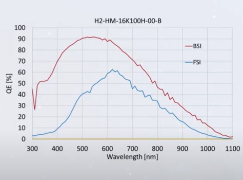
Early sensors were all used frontside illumination, and everybody lived with that until about 10 years ago when backside illumination was innovated and refined. The key insight was to let the photons hit the light-sensitive surface first, with the sensor’s wiring layer on the other side. This greatly improves quantum efficiency, as seen in the graph below:

QE substantially enhanced using backside illumination (BSI – Courtesy Teledyne DALSA

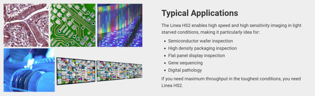
Applications

This camera series is designed for high-speed imaging in light staved conditions. Applications include but are not limited to inspecting flat panel displays, semiconductor wafers, high density interconnects, and diverse life science uses.

Courtesy Teledyne DALSA

Line scan cameras

You may already be a user of line scan cameras. If you are new to that branch of machine vision, compare and contrast line scan vs. area scan imaging. If you want the concept in a phrase or two, think “slice” or line of pixels obtained as the continuous wide target is passed beneath the camera. Repeat indefinitely. Can be used to monitor quality, detect defects, and/or tune controls.

Time Delay Integration (TDI)

Perhaps you even use Time Delay Integration (TDI) technology already. TDI builds on top of “simple” line scan by tracking how a pixel appears across several successive time slices, turning motion blur into an asset through hardware or software averaging and analysis.

Maybe you already have one or more of Teledyne DALSA’s prior-generation Linea HS line scan cameras. They feature the same pixel size, optics, and cables as the new Linea HS2 series. With a 2.5x speed increase the Linea HS2 provides a seamless upgrade. The Linea HS2 offers an optional cooling accessory to enhance thermal stability.

Frame grabber

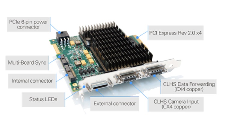
The Linea HS2 utilizes Camera Link High Speed (CLHS) to match the camera’s data output rate with an interface that can keep up. Teledyne DALSA manufactures not just the camera, but also the Xtium2-CL MX4 Camera Link Frame Grabber.

Xtium2-CL MX4 Camera Link Frame Grabber – Courtesy Teledyne DALSA

The Xtium2-CL MX4 is built on next generation CLHS technology and features:

  • 16 Gigapixels per second
  • dual CLHS CX4 connectors
  • drives active optical cables
  • supports parallel data processing in up to 12 PCs
  • allows cable lengths over 100 meters with complete EMI immunity

Which camera to choose?

As this blog is released, the Linea HS2, with 16k/5μm resolution provides an industry leading maximum line rate of 1 MHz, or 16 Gigapixels per second data throughput. Do you need the speed and sensitivity of this camera? Or is one of the “kid brother” models enough – they are already highly performant before the new kid came along. We can help you sort out the specifications according to your application requirements.

1st Vision’s sales engineers have over 100 years of combined experience to assist in your camera and components selection.  With a large portfolio of cameras, lenses, cables, NIC cards and industrial computers, we can provide a full vision solution!

About you: We want to hear from you!  We’ve built our brand on our know-how and like to educate the marketplace on imaging technology topics…  What would you like to hear about?… Drop a line to info@1stvision.com with what topics you’d like to know more about

Color models join Teledyne DALSA AxCIS Line Scan Series

As anticipated when Teledyne DALDA’s AxCIS Line Scan Series was introduced a few months ago, color models have now been released. The “CIS” in the product name stands for Contact Image Sensor. In fact a CIS doesn’t actually contact the object being imaged – but it’s so close to touching that the term has become vision industry jargon to help us orient to the category.

Courtesy Teledyne DALSA

What can CIS do for me?

Think “specialized line scan”. Line scan in that it’s a linear array of sensors (vs. and area scan camera), requiring motion to create each successive next slice. And “specialized” in that CIS is positioned very close to the target, Plus low power requirements. And excellent price-performance characteristics.

Why is the new color offering interesting?

Just as with area scan imaging, if the application can be solved with monochrome sensors, that’s often preferred – since monochrome sensors, lensing, and lighting are simpler. If one just needs edge detection and contrast achievable with monochrome – stay monochrome! BUT sometimes color is the sole differentiator for an application, so the addition of color members to the AxCIS family can be a game changer.

Why Teledyne DALSA AxCIS in particular?

A longtime leader in line scan imaging, Teledyne DALSA introduces the AxCIS series in 2023 and continues to release new models and features. Vision Systems Design named the AxCIS family of high-speed high-resolution integrated imaging modules with their 2024 Gold Honoree Award.

Courtesy Vision Systems Design

AxCIS Series Key Attributes

  • Compact modules integrating sensors, lenses and lights
  • Option to customize the integrated lighting for specific CRI to aid in color measurement.
  • Current width choices 400mm (16 inches) or 800mm (32 inches)
  • Customizable lengths coming, in addition to the 400mm and 800mm models
  • CIS covers entire FOV – without missing any pixels and without using interpolation, allowing for accurate measurements. The competition has gaps between sensors causing areas which are not imaged and inability to measure properly
  • Selectable pixel sizes up to 900dpi
  • Gradient index lenses are used so there is no parallax and essentially telecentric.  (Great for gauging applications)  
  • Binning support, summed to provide brighter images
  • 4 available AOIs
  • CameraLink HS interface
  • Up to 120 kHz line rates … and cables lengths to 300m
  • No alignment or calibration required – lighting and sensors are pre-aligned
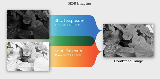
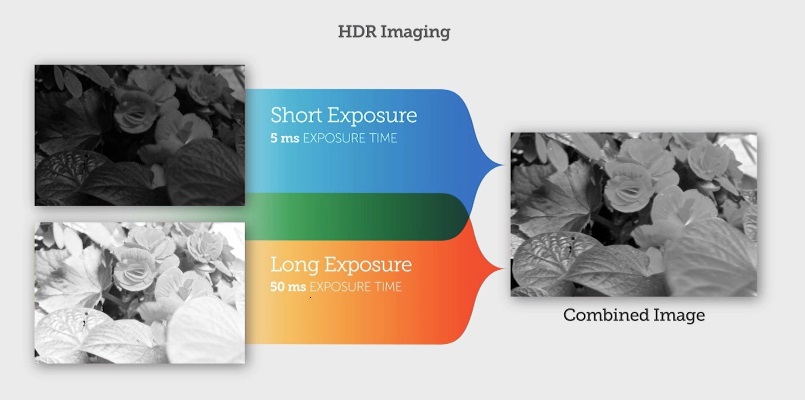
  • HDR imaging with dual exposure mode

Get quote

See specs for specific models in the Teledyne DALSA AxCIS Series.

Contact us for a quote

HDR – a closer look

HDR Imaging – High Dynamic Range – Courtesy Teledyne DALSA

By using two adjacent rows of sensors, one row may be used for a short exposure to capture the rapidly saturated portions of an image. A second row of sensors can take a longer exposure, creating nuanced pixel values of areas that would otherwise have been undersaturated. Then the values are combined to a composite image with a wider dynamic range with more useful information to be interpreted by the processing algorithms.

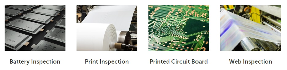
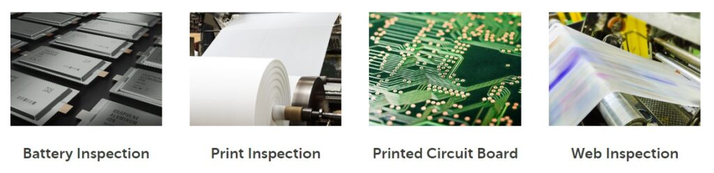
Applications

While not limited to the following, popular applications include:

Popular AxCIS applications – Courtesy Teledyne DALSA

Want to see other Teledyne DALSA imaging products?

Teledyne DALSA is long-recognized as a leader and innovator across the diverse range of imaging products – click here to see all Teledyne DALSA products.

1st Vision’s sales engineers have over 100 years of combined experience to assist in your camera and components selection.  With a large portfolio of cameras, lenses, cables, NIC cards and industrial computers, we can provide a full vision solution!

About you: We want to hear from you!  We’ve built our brand on our know-how and like to educate the marketplace on imaging technology topics…  What would you like to hear about?… Drop a line to info@1stvision.com with what topics you’d like to know more about. 

Teledyne DALSA AxCIS Contact Image Sensor Modules

Teledyne DALSA has released the AxCIS 800mm mono/HDR, and the AxCIS 400mm mono, the first two members of a new flexible and scalable product family of Contact Image Sensors (CIS). As other members are released, users can choose fields of view (FoV) in 100mm increments, e.g. 400mm, 500mm, 600mm, 700mm, and 800mm.

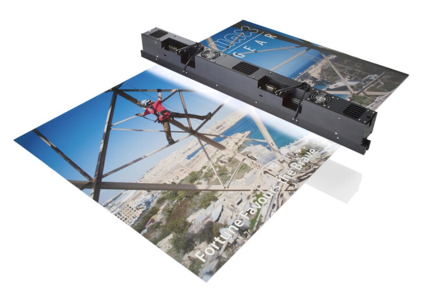
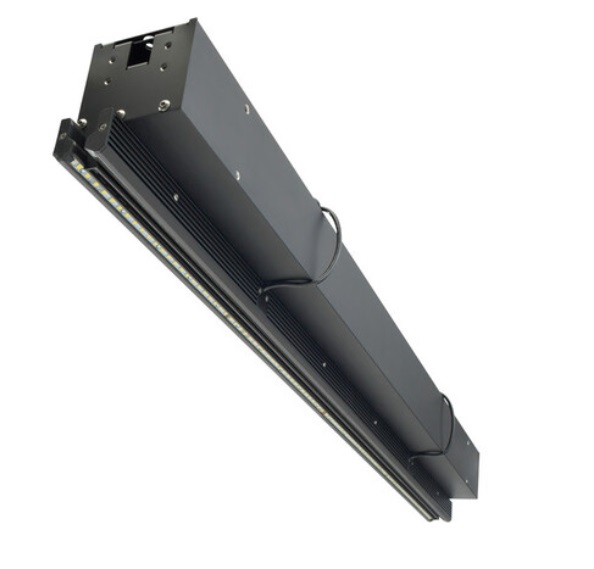
AxCIS 800mm lighting and scanning – Courtesy Teledyne DALSA
AxCIS Contact Image Sensor showing sensor array
– Courtesy Teledyne DALSA

Contact Image Sensor vs. Linescan

Actually that’s a trick heading! A contact image sensor (CIS) is a type of linescan camera. Conventionally, the industry calls it a linescan camera if the sensor uses CMOS or CCD. while it’s called a CIS if it bundles a linear array of detectors, lenses, and lights.

But CIS is very much a linescan type of camera, With a 2D area scan camera, a comprehensive pixel array captures hundreds or thousands of (X,Y) values in a single exposure. But a Contact Image Sensor requires either the target or the imaging unit to move, as a single exposure is a slice of Y values at a given coordinate X. Motion is required to step across the set of X values.

Two more notes:

  1. The set of X values may be effectively infinite, as with “web inspection” applications
  2. The term “contact” in CIS is a bit of a misnomer. The sensor array is in fact “very close” to the surface, which must thereby be essentially flat in order to sustain collision-free motion. But it doesn’t actually touch.

AxCIS key attributes include:

  • 28um pixel size (900dpi)
  • high speed 120KHz using Camera Link HS
  • HDR imaging with dual exposure mode
  • optional LED lighting
  • fiberoptic cables immune to EMI radiation

Application areas share the characteristics of flat surfaces and motion of either the target or the sensor, since contact image sensing (CIS) is a form of linescan imaging.

Courtesy Teledyne DALSA

HDR imaging

Some targets are inherently challenging to obtain sufficient saturation for the darker regions while avoiding over-saturation for the lighter areas. The multiline sensors used in AxCIS utilize a sensor array with:

  • One row of the sensor array that can have a longer exposure for dark scenes
  • Another row using a shorter exposure for light scenes

The camera then combines the images, as shown below. The technique is referred to as High Dynamic Range imaging – HDR.

Ilustration of HDR Imaging – Courtesy Teledyne DALSA

Want to know more about area scan vs line scan? And multifield line scan? And other Teledyne DALSA linescan products, in which they have years of expertise? See our blog “What can multifield linescan imaging do for me?“.

For details on the AxCIS CIS family, please see the product page with detailed specs.

If you’ve had enough reading, and want to speak with a real live engineer, just call us at 978-474-0044.

1st Vision’s sales engineers have over 100 years of combined experience to assist in your camera and components selection.  With a large portfolio of lenses, cables, NIC cards and industrial computers, we can provide a full vision solution!