Effilux LED bar lights for machine vision – adjustable and modular!

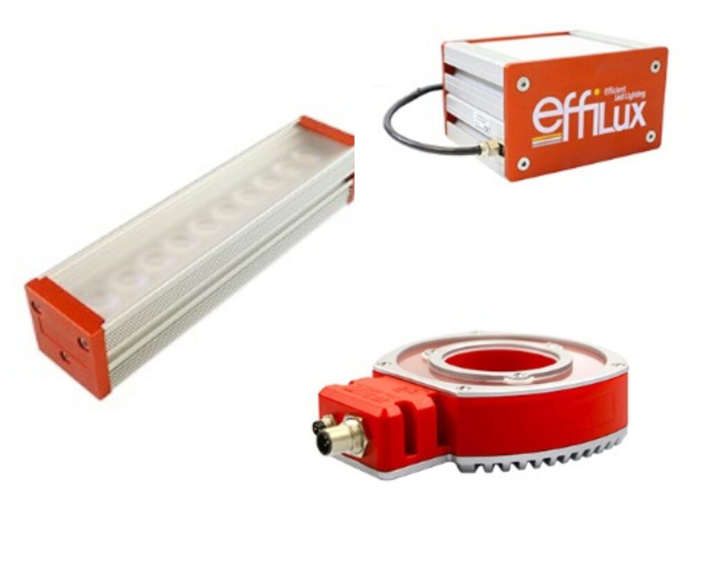
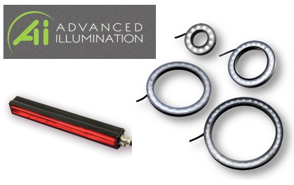
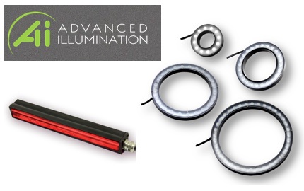
Various LED bar configurations

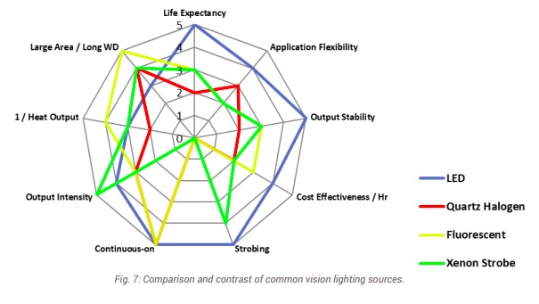
Effective machine vision outcomes depend upon getting a good image. A well-chosen sensor and camera are a good start. So is a suitable lens. Just as important is lighting, since one needs photons coming from the object being imaged to pass through the lens and generate charges in the sensor, in order to create the digital image one can then process in software. Elsewhere we cover the full range of components to consider, but here we’ll focus on lighting.

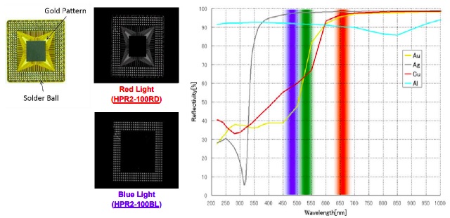
While some applications are sufficiently well-lit without augmentation, many machine vision solutions are only achieved by using lighting matched to the sensor, lens, and object being imaged. This may be white light – which comes in various “temperatures”; but may also be red, blue, ultra-violet (UV), infra-red (IR), or hyper-spectral, for example.

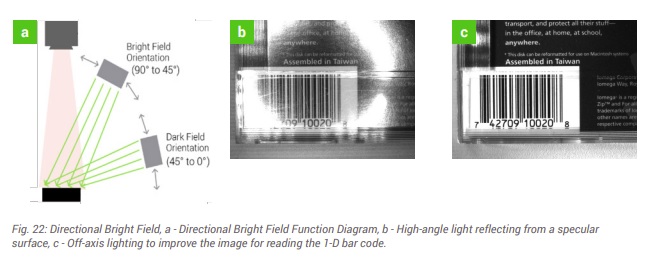
LED bar lights are a particularly common choice, able to provide bright field or dark field illumination, according to how they are deployed. The illustrations below show several different scenarios.

Example uses of LED bar lights

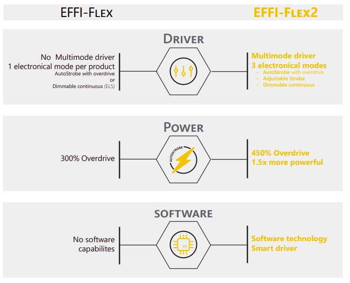
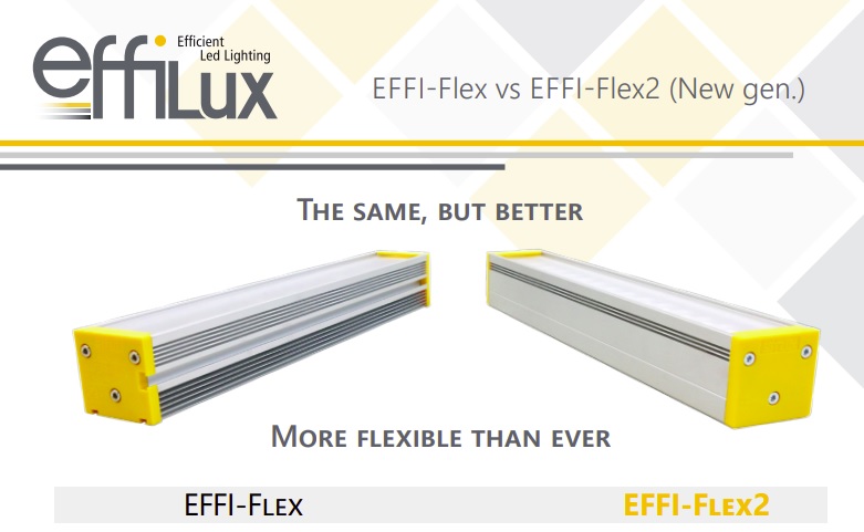
LED light bars conventionally had to be factory assembled for specific customer requirements, and could not be re-configured in the field. The EFFI-Flex LED bar breaks free from many of those constraints. Available in various lengths, many features can be field-adapted by the user, including, for example:

  • Color of light emitted
  • Emitting angle
  • Optional polarizer
  • Built-in controller – continuous vs. strobed option
  • Diffuser window opacity: Transparent, Semi-diffusive, Opaline
EFFI-Flex user-configurable LED bar
Contact us for a quote

While the EFFI-Flex offers maximum configurability, sister products like the EFFI-Flex-CPT and EFFI-Flex-IP69K offer IP67 and IP69 protection, respectively, ideal for environments requiring more ruggedized or washdown components.

SWIR LED bar, backlight, and ringlight

Do you have an application you need tested with lights? Contact us and we can get your parts in the lab, test them and send images back.   If your materials can’t be shipped because they are spoilable foodstuffs, hazmat items, or such, contact us anyway and we’ll figure out how to source the items or bring lights to your facility.

Test and optimize lighting with customer materials

1st Vision’s sales engineers have over 100 years of combined experience to assist in your camera and components selection.  With a large portfolio of lensescablesNIC card and industrial computers, we can provide a full vision solution!

Components needed for machine vision and industrial imaging systems

Machine vision and industrial imaging systems are used in various applications ranging from automated quality control inspection, bottle filling, robot pick-and-place applications, autonomous drone or vehicle guidance, patient monitoring, agricultural irrigation controls, medical testing, metrology, and countless more applications.

Imaging systems typically include a least a camera and lens, and often also include one or more of specialized lighting, adapter cards, cables, software, optical filters, power supply, mount, or enclosure.

At 1stVision we’ve created a resource page is intended to make sure that nothing in a planned imaging application has been missed.  There are many aspects on which 1stVision can provide guidance.   The main components to consider are indicated below.

Diverse cameras

Cameras: There are area scan cameras for visible, infrared, and ultraviolet light, used for static or motion situations.  There are line scan cameras, often used for high-speed continuous web inspection.  Thermal imaging detects or measures heat.  SWIR cameras can identify the presence or even the characteristics of liquids.  The “best” camera depends on the part of the spectrum being sensed, together with considerations around motion, lighting, surface characteristics, etc.

An assortment of lens types and manufacturers

Lens: The lens focuses the light onto the sensor, mapping the targeted Field of View (FoV) from the real world onto the array of pixels.  One must consider image format to pair a suitable lens to the camera.  Lenses vary by the quality of their light-passing ability, how close to the target they can be – or how far from it, their weight (if on a robot arm it matters), vibration resistance,  etc.  See our resources on how to choose a machine vision lens.  Speak with us if you’d like assistance, or use the lens selector to browse for yourself.

Lighting: While ambient light is sufficient for some applications, specialized lighting may also be needed, to achieve sufficient contrast.  And it may not just be “white” light – Ultra-Violet (UV) or Infra-Red (IR) light, or other parts of the spectrum, sometimes work best to create contrast for a given application – or even to induce phosphorescence or scatter or some other helpful effect.  Additional lighting components may include strobe controllers or constant current drivers to provide adequate and consistent illumination. See also Lighting Techniques for Machine Vision.

Optical filter: There are many types of filters that can enhance application performance, or that are critical for success.  For example a “pass” filter only lets certain parts of the spectrum through, while a “block” filter excludes certain wavelengths.  Polarizing filters reduce glare.  And there are many more – for a conceptual overview see our blog on how machine filters create or enhance contrast

Don’t forget about interface adapters like frame grabbers and host adapters; cables; power supplies; tripod mounts; software; and enclosures. See the resource page to review all components one might need for an industrial imaging system, to be sure you haven’t forgotten anything.

1st Vision’s sales engineers have over 100 years of combined experience to assist in your camera and components selection.  With a large portfolio of lensescablesNIC card and industrial computers, we can provide a full vision solution!
How machine vision filters create contrast in machine vision applications

Before and after applying filters

Imaging outcomes depend crucially on contrast. It is only by making a feature “pop” relative to the larger image field in which the feature lies, that the feature can be optimally identified by machine vision software.

While sensor choice, lensing, and lighting are important aspects in building machine vision solutions with effective contrast creation, effective selection and application of filters can provide additional leverage for many applications. Often overlooked or misunderstood, here we provide a first-look at machine vision filter concepts and benefits.

Before and after applying filters

In the 4 image pairs above, each left-half image was generated with the same sensor, lighting, and exposure duration as the corresponding right-half images. But the right-half images have had filters applied to reduce glare or scratch-induced scatter, separate or block certain wavelengths, for example. If your brain finds the left-half images to be difficult to discern, image processing software wouldn’t be “happy” with the left-half either!

While there are also filtering benefits in color and SWIR imaging, it is worth noting that we started above with examples shown in monochrome. Surprising to many, it can often be both more effective and less expensive to create machine vision solutions in the monochrome space – often with filters – than in color. This may seem counter-intuitive, since most humans enjoy color vision, and use if effectively when driving, judging produce quality, choosing clothing that matches our skin tone, etc. But compared to using single-sensor color cameras, monochrome single sensor cameras paired with appropriate filters:

  • can offer higher contrast and better resolution
  • provide better signal-to-noise ratio
  • can be narrowed to sensitivity in near-ultraviolet, visible and near-infrared spectrums

These features give monochrome cameras a significant advantage when it comes to optical character recognition and verification, barcode reading, scratch or crack detection, wavelength separation and more. Depending on your application, monochrome cameras can be three times more efficient than color cameras.

Identify red vs. blue items

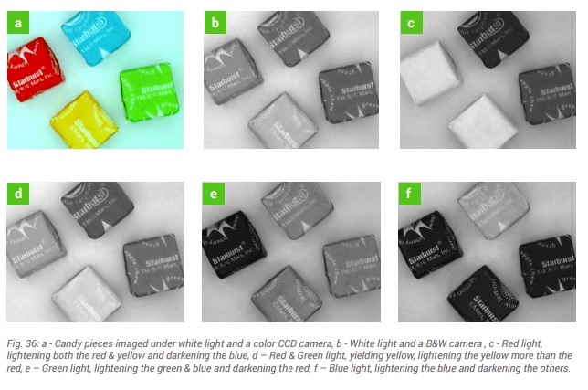
Color cameras may be the first thought when separating items by color, but it can be more efficient and effective to use a monochrome camera with a color bandpass filter. As shown above, to brighten or highlight an item that is predominantly red, using a red filter to transmit only the red portion of the spectrum can be used, blocking the rest of the transmitted light. The reverse can also work, using a blue filter to pass blue wavelengths while blocking red and other wavelengths.

Here we have touched on just a few examples, to whet the appetite. We anticipate developing a Tech Brief with a more in depth treatment of filters and their applications. We partner with Midwest Optical to offer you a wide range of filters for diverse application solutions.

Contact us

1st Vision’s sales engineers have an average of 20 years experience to assist in your camera selection.  Representing the largest portfolio of industry leading brands in imaging components, we can help you design the optimal vision solution for your application.

About Us | 1stVision

1st Vision is the most experienced distributor in the U.S. of machine vision cameras, lenses, frame grabbers, cables, lighting, and software in the industry.

Types of 3D imaging systems – and benefits of Time of Flight (ToF)

Time Of Flight Gets Precise: Whitepaper

2D imaging is long-proven for diverse applications from bar code reading to surface inspection, presence-absence detection, etc.  If you can solve your application goal in 2D, congratulations!

But some imaging applications are only well-solved in three dimensions.  Examples include robotic pick and place, palletization, drones, security applications, and patient monitoring, to name a few.

For such applications, one must select or construct a system that creates a 3D model of the object(s).  Time of Flight (ToF) cameras from Lucid Vision Labs is one way to achieve cost-effective 3D imaging for many situations.

ToF systems setup
ToF systems have a light source and a sensor.

ToF is not about objects flying around in space! It’s about using the time of flight of light, to ascertain differences in object depth based upon measurable variances from light projected onto an object and the light reflected back to a sensor from that object.  With sufficiently precise orientation to object features, a 3D “point cloud” of x,y,z coordinates can be generated, a digital representation of real-world objects.  The point cloud is the essential data set enabling automated image processing, decisions, and actions.

In this latest whitepaper we go into depth to learn:
1. Types of 3D imaging systems
2. Passive stereo systems
3. Structured light systems
4. Time of Flight systems
Whitepaper table of contents
Download

Let’s briefly put ToF in context with other 3D imaging approaches:

Passive Stereo: Systems with cameras at a fixed distance apart, can triangulate, by matching features in both images, calculating the disparity from the midpoint.  Or a robot-mounted single camera can take multiple images, as long as positional accuracy is sufficient to calibrate effectively.

Challenges limiting passive stereo approaches include:

Occlusion: when part of the object(s) cannot be seen by one of the cameras, features cannot be matched and depth cannot be calculated.

ToF diagram
Occlusion occurs when a part of an object cannot be imaged by one of the cameras.

Few/faint features: If an object has few identifiable features, no matching correspondence pairs may be generated, also limiting essential depth calculations.

Structured Light: A clever response to the few/faint features challenge can be to project structured light patterns onto the surface.  There are both active stereo systems and calibrated projector systems.

Active stereo systems are like two-camera passive stereo systems, enhanced by the (active) projection of optical patterns, such as laser speckles or grids, onto the otherwise feature-poor surfaces.

ToF diagram
Active stereo example using laser speckle pattern to create texture on object.

Calibrated projector systems use a single camera, together with calibrated projection patterns, to triangulate from the vertex at the projector lens.  A laser line scanner is an example of such a system.

Besides custom systems, there are also pre-calibrated structured light systems available, which can provide low cost, highly accurate solutions.

Time of Flight (ToF): While structured light can provide surface height resolutions better than 10μm, they are limited to short working distances. ToF can be ideal for or applications such as people monitoring, obstacle avoidance, and materials handling, operating at working distances of 0.5m – 5m and beyond, with depth resolution requirements to 1 – 5mm.

ToF systems measure the time it takes for light emitted from the device to reflect off objects in the scene and return to the sensor for each point of the image.  Some ToF systems use pulse-modulation (Direct ToF).  Others use continuous wave (CW) modulation, exploiting phase shift between emitted and reflected light waves to calculate distance.

The new Helios ToF 3D camera from LUCID Vision Labs, uses Sony Semiconductor’s DepthSense 3D technology. Download the whitepaper to learn of 4 key benefits of this camera, example applications, as well as its operating range and accuracy,

Download whitepaper
Download whitepaper
Time Of Flight Gets Precise: Whitepaper
Download Time of Flight Whitepaper

Have questions? Tell us more about your application and our sales engineer will contact you.

1st Vision’s sales engineers have an average of 20 years experience to assist in your camera selection.  Representing the largest portfolio of industry leading brands in imaging components, we can help you design the optimal vision solution for your application.