Kowa HC-V 1″ C-mount industrial lenses feature a patented design that ensures dependable performance, and consistently clear, crisp images with uniform brightness across the entire image, including the corners. These ruggedized lenses are built for use in harsh environments to withstand strong vibrations and impacts.
Interchangeable iris plates and a two-way reversible nut enable precise focus adjustments, and glued inner glass elements ensure stability. HC-V lenses are compatible with 1″ format sensors including Sony IMX174, CMOSIS CMV4000, and Sony IMX249 sensors. Designed for sensors with a pixel size as small as 5.0μm.
Or for expert assistance just call us at 978-474-0044.
Interchangeable iris plates
The HC-V patented design includes interchangeable iris plates. Secured by a lock nut, this insures precise focus that’s vibration resistant. Ideal for rugged industrial environments.
HC-V ruggedized lens series overview – Courtesy Kowa
How to change the iris plates
How to change the iris plates – Courtesy Kowa
Happy to help
We’re pleased to distribute Kowa lenses, and to advise customers on all aspects of machine vision component selection. Whether for sensor, camera, lens, lighting, software, or other components, tell us about your application, and we’ll be happy to guide you to optimal choices. By phone we’re at 978-474-0044, or key in a few application notes below and we’ll reach out to you at your convenience.
About you: We want to hear from you! We’ve built our brand on our know-how and like to educate the marketplace on imaging technology topics… What would you like to hear about?… Drop a line to info@1stvision.com with what topics you’d like to know more about.
Remember when machine vision pioneers got stuff done with VGA sensors at 0.3MP? And the industry got really excited with 1MP sensors? Moore’s law keeps driving capacities and performance up, and relative costs down. With the Teledyne e2v Emerald 67MP sensor, cameras like the Genie Nano-10GigE-8200 open up new possibilities.
12MP sensor image – Courtesy Teledyne DALSA
67MP sensor image – Courtesy Teledyne DALSA
So what? 67MP view above right doesn’t appear massively compelling…
Well at this view, without zooming in, we’d agree….
But at 400% zoom, below, look at the pixelation differences:
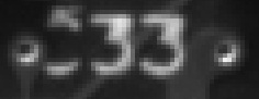
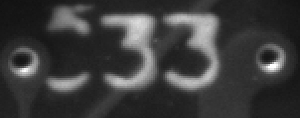
Both images below show the same target region, with the same lighting and lens, and each zoomed (with Gimp) to 400%. There is so much pixelation in the 12MP image to raise doubts about effective edge detection on either the identifying digits (33) or for the metal-rimmed holes. Whereas the 67MP image has far less pixelation, thereby passing a readily usable image to the host for processing. How much resolution does your application require?
12MP zoomed 400%
67MP zoomed 400%
Important “aside”: Sensor format and lens quality also important
Sensor format refers to the physical size of the sensor and the pixel shape and pixel density. Of course the lens must physically mount to the camera body (e.g. S, C, M42, etc.), but it must also create an image circle that appropriately covers the sensor’s pixel array. The Genie Nano-10Gige-8200 uses the Teledyne e2V Emerald 67M packs just over 67 million pixels, each square pixel just 2.5 µm wide and high, onto a CMOS sensor measuring only 59mm x 59mm.
Consider other good quality cameras and sensors, with pixel sizes in the 4 – 5 µm range, which leads to EITHER fewer pixels overall in the same size sensor array; OR to a much larger sensor to accommodate more pixels. The former may limit what can be accomplished with a single camera. The latter would necessarily make the camera body larger, the lens mount larger, and the lens more expensive to manufacture.
The lens quality, typically expressed via the Modulation Transfer Function (MTF), is also important. Not all lenses are created equal! A “good” quality lens may be enough for certain applications. For more demanding applications, one would be wasting a large format sensor if the lens’ performance fails below the sensor’s capabilities.
Two different lenses were used to take the above images, both fitting the sensor size. However the right image was taken with a lens designed for smaller pixels versus the left. – Courtesy Teledyne DALSA
The high-level views of the test chart above tease at the point we’re making, but it really pops if we zoom in. Look at the difference in contrast in the two images below!
Lens nominally a fit for the sensor format and mount type, but NOT designed for 2.5 µm pixels.
Lens designed for 2.5 µm pixels.
The takeaway point of this segment is lensing matters! The machine vision field benefits users tremendously with segmented sensor, camera, lensing, and lighting suppliers. Even within the same supplier’s lineup, there are often sensors or lenses pitched at differing performance requirements. Consider our Knowledge Base guide on Lens Quality Considerations. Or call us at 978-474-0044.
Another example:
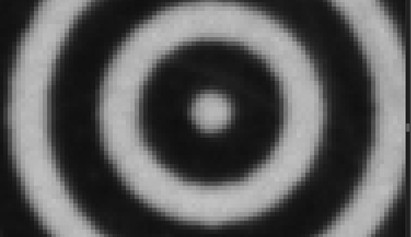
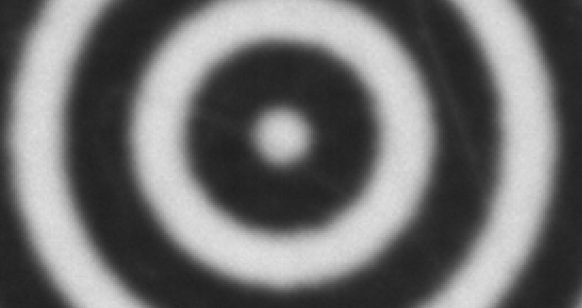
Below see the same concentric rings of a test chart, under the same lighting. The left imaged was obtained with a good 12MP sensor and good quality lens matched to the sensor format and pixel size. The right imaged used the 67MP sensor in the Genie-Nano-10GigE-8200, also with a well-matched lens.
12MP sensor, zoomed 1600%
67MP sensor, zoomed to same FOV
If you need a single-camera solution for a large target, with high levels of detail, there’s no way around it – one needs enough pixels. Together with a well-suited lens.
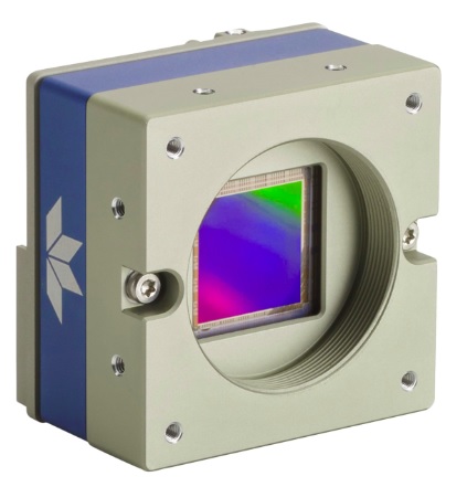
Genie Nano 10GigE 8200 – Courtesy Teledyne DALSA
The Genie Nano 10GigE 8200, in both monochrome and color versions, is more affordable than you might think.
Once more with feeling…
Which of the following images will lead to the more effective outcomes? Choose your sensor, camera, lens, and lighting accordingly. Call us at 978-474-0044. Our sales engineers love to create solutions for our customers.
About you: We want to hear from you! We’ve built our brand on our know-how and like to educate the marketplace on imaging technology topics… What would you like to hear about?… Drop a line to info@1stvision.com with what topics you’d like to know more about.
Machine vision practitioners, regardless of application or lens type, know that contrast is essential. Without sharp definition, features cannot be detected effectively.
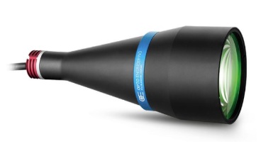
When using a telecentric lens for precision optical 2-D measurements, ideally one should also use collimated lighting. Per the old adage about a chain being only as good as its weakest link, why invest in great lensing and then cut corners on lighting?
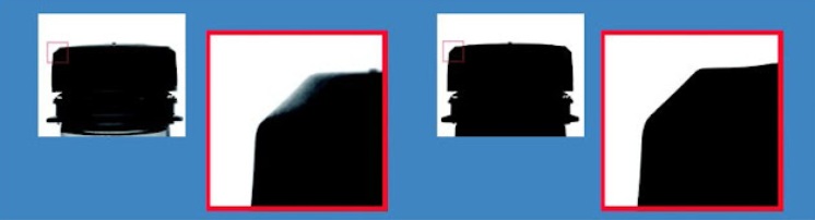
WITH collimated light expect high edge definition:
The cost of the light typically pays for itself relative to quality outcomes. Below see red-framed enlargements of the same region of a part being imaged by the same telecentric lens.
The left-hand image was taken with a conventional backlight – note how the light wraps around the edge, creating “confusion” and imprecision due to refracted light coming from all angles.
The right-hand image was obtained with a collimated backlight – with excellent edge definition.
While telecentric imaging is a high-performance subset of the larger machine vision field in general, the same principles of resolution apply. It takes several pixels to confidently resolve any given feature – such as an edge – so any “gray areas” induced by lower quality lighting or optics would drag down system performance. See our blog and knowledge-base coverage of resolution for more details.
Collimated lighting in more detail
Above we see the results of using “diffuse” vs. “collimated” light sources, which are compelling. But what is a collimated light and how does it work so effectively?
UNLIKE a diffuse backlight, whose rays emanate towards the object at angles ranging from 0 to almost 180°, a collimated backlight sends rays with only very small deviations from perfectly parallel. Since parallel rays are also all that the telecentric lens receives and transmits on to the camera sensor, stray rays are mitigated and essentially eliminated.
The result is a high-contrast image which is easier to process with high-reliability. Furthermore, shutter speeds are typically faster, achieving necessary saturation more quickly, thereby shortening cycle times and increasing overall throughput.
Many lights to choose from:
The video below shows a range of light types and models, including clearly labeled direct, diffuse, and collimated lights.
Several light types – including clearly labeled collimated lights
[Optional] Telecentric concepts overview
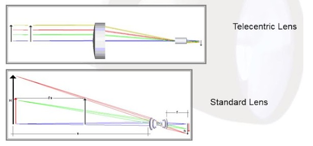
Below please compare the diagrams that show how light rays travel from the target position on the left, through the respective lenses, and on to the sensor position on the far right.
A telecentric lens is designed to insure that the chief rays remain parallel to the optical axis. The key benefit is that (when properly focused and aligned) the system is invariant to the distance of the object from the lens. This effectively ignores light rays coming from other angles of incidence, and thereby supports precise optical measurement systems – a branch of metrology.
If you’d like to go deeper on telecentrics, see the following two resources:
About you: We want to hear from you! We’ve built our brand on our know-how and like to educate the marketplace on imaging technology topics… What would you like to hear about?… Drop a line to info@1stvision.com with what topics you’d like to know more about.
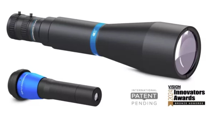
Nano hypercentric lenses designed for the inspection of small cavities and hollow parts with diameters from 0.75 to 10 mm. That’s the diameter of a drinking straw – and narrower!
HCN13010 and HCN13040 Nano Hypercentric lenses for small cavities – Courtesy Opto Engineering
Hypercentric lenses once more with feeling
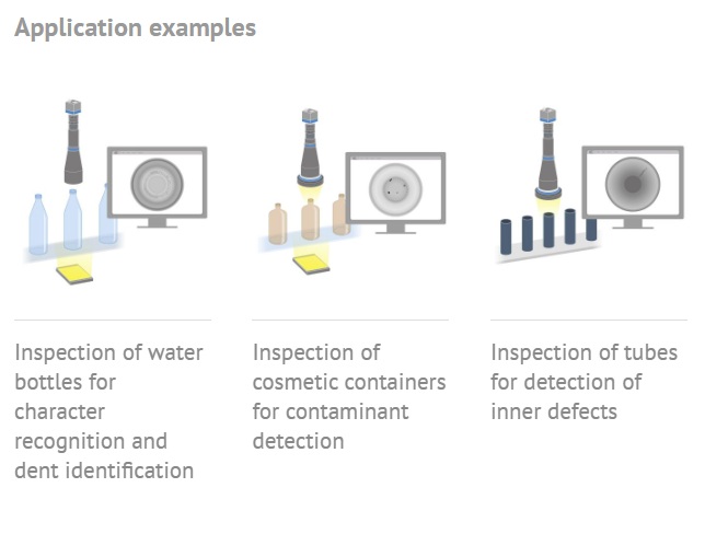
Recently we introduced Opto Engineering’s HC hypercentric 360° lenses. They image cavity interiors from the outside by utilizing a specialized optical path that allows light to pass through bottlenecks and narrow openings. The variable iris provides maximum flexibility and a wide viewing angle to clearly image the fine details of the object. Their unique design facilitates complete internal surface inspection with no need to use a probe, rotate the object or use a complex multi-camera system.
HC 360° Series applications across whole lens family
Courtesy Opto Engineering
HCN Hypercentric nano lenses inspect tiny cavities from the outside
Consider cavities as small as 0.75 mm (0.029 in) ranging up to 10 mm (0.39 in), for items in the order of a drinking straw diameter (and smaller). These interiors can be inspected from the outside looking in, with the HCN Series lenses.
2 minute overview of lenses for hollow-part inspection – Courtesy Opto Engineering
About you: We want to hear from you! We’ve built our brand on our know-how and like to educate the marketplace on imaging technology topics… What would you like to hear about?… Drop a line to info@1stvision.com with what topics you’d like to know more about.