Kowa FC24M C-mount lens series

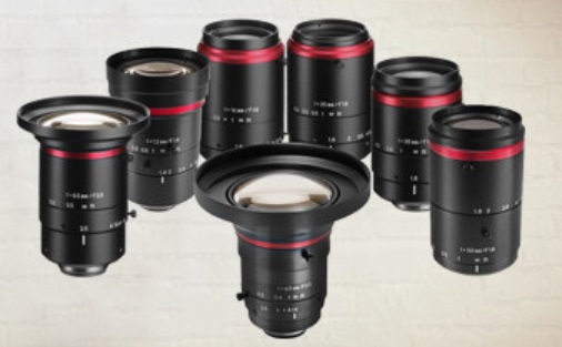
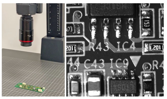
With 9 members in the Kowa FC24M lens series, focal lengths range from 6.5mm through 100mm. Ideal for sensors like the 1.1″ Sony IMX183, 530/540, 253 and IMX304, these C-mount lenses cover any sensor up to 14.1mm x 10.6mm, with no vignetting. Their design is optimized for sensors with pixel sizes as small as 2.5µm – but of course work great on pixels larger than that as well.

Kowa FC24M C-mount lenses – Courtesy Kowa

Lens selection

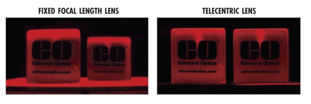
Machine vision veterans know that lens selection ranks right up there with camera/sensor choice, and lighting, as determinants in application success. For an introduction or refresher, see our knowledge base Guide to Key Considerations in Machine Vision Lens Selection.

Click to contact
Give us a brief idea of your application and we will contact you with options.

Noteworthy features

Particularly compelling across the Kowa FC24M lens series is the floating mechanism system. Kowa’s longer name for this is the “close distance aberration compensation mechanism.” It creates stable optical performance at various working distances. Internal lens groups move independently of each other, which optimizes alignment compared to traditional lens design.

Kowa FC24M lenses render sharp images with minimal distortion – Courtesy Kowa

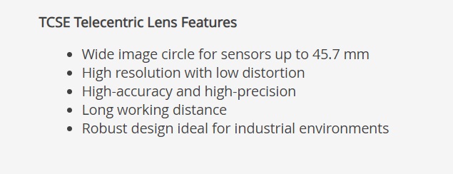
Listing all the key features together:

  • Floating mechanism system (described above)
  • Wide working range… and as close at 15 cm MOD
  • Durable construction … ideal for industrial applications
  • Wide-band multi-coating – minimizes flare and ghosting from VIS through NIR
High resolution down to pixels as small as 2.5um – Courtesy Kowa

Video overview shows applications

Applications include manufacturing, medical, food processing, and more. View short one-minute video:

Kowa FC24M key features and example applications – Courtesy Kowa

What’s in a family name?

Let’s unpack the Kowa FC24M lens series name:

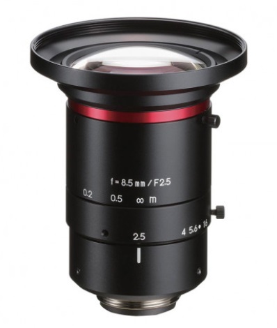
F is for fixed. With focal lengths at 9 step sizes from 6 – 100, lens design is kept simple and pricing is correspondingly competitive.

C is for C-mount. It’s one of the most popular camera/lens mounts in machine vision, with a lot of camera manufacturers offering diverse sensors designed in to C-mount housings.

24M is for 24 Megapixels. Not so long ago it was cost prohibitive to consider sensors larger than 20M. But as with most things in the field of electronics, the price : performance ratio keeps moving in the user’s favor. Many applications benefit from sensors in this size.

And the model names?

Model names include LM6FC24M, LM8FC24M, …, LM100FC24M. So the focal length is specified by the digit(s) just before the family name. i.e. the LM8FC24M has a focal length of 8mm. In fact that particular model is technically 8.5mm but per industry conventions one rounds or truncates to common de facto sizes.

LM8FC24M 8.5mm focal length – Courtesy Kowa

See the full brochure for the Kowa FC24M lens series, or call us at 978-474-0044.

1st Vision’s sales engineers have over 100 years of combined experience to assist in your camera and components selection.  With a large portfolio of cameraslensescablesNIC cards and industrial computers, we can provide a full vision solution! We’re big enough to carry the best cameras, and small enough to care about every image.

About you: We want to hear from you!  We’ve built our brand on our know-how and like to educate the marketplace on imaging technology topics…  What would you like to hear about?… Drop a line to info@1stvision.com with what topics you’d like to know more about. 

Depth of Field – a balancing act

Most who are involved with imaging have at least some understanding of depth of field (DoF). DoF is the distance between the nearest and furthest points that are acceptably in focus. In portrait photography, one sometimes seeks a narrow depth of field to draw attention to the subject, while intentionally blurring the background to a “soft focus”. But in machine vision, it’s often preferred to maximize depth of field – that way if successive targets vary in their Z dimension – or if the camera is on a moving vehicle – the imaging system can keep processing without errors or waste.

Making it real

Suppose you need to see small features on an item that has various heights (Z dimension). You may estimate you need a 1″ depth of field. You know you’ve got plenty of light. So you set the lens to f11 because the datasheet shows you’ll reach the depth of field desired. But you can’t resolve the details! What’s up?

So I should maximize DoF, right?

Well generally speaking, yes – to a point. The point where diffraction limits negatively impact resolution. If you read on, we aim to provide a practical overview of some important concepts and a rule of thumb to guide you through this complex topic without much math.

Aperture, F/#, and Depth of Field

Aperture size and F/# are inversely correlated. So a low f/# corresponds to a large aperture, and a high f/# signifies a small aperture. See our blog on F-Numbers aka F-Stops on the way the F-numbers are calculated, and some practical guidance.

Per the illustration below, a large aperture restricts DoF, while a small aperture maximizes the DoF. Please take a moment to compare the upper and lower variations in this diagram:

Correlation between aperture and Depth of Field – Courtesy Edmund Optics

If we maximize depth of field…

So let’s pursue maximizing depth of field for a moment. Narrow the aperture to the smallest setting (the largest F-number), and presto you’ve got maximal DoF! Done! Hmm, not so fast.

First challenge – do you have enough light?

Narrowing the aperture sounds great in theory, but for each stop one narrows the aperture, the amount of light is halved. The camera sensor needs to receive sufficient photons in the pixel wells, according to the sensor’s quantum efficiency, to create an overall image with contrast necessary to process the image. If there is no motion in your application, perhaps you can just take a longer exposure. Or add supplemental lighting. But if you do have motion or can’t add more light, you may not be able to narrow the aperture as far as you hoped.

Second challenge – the Airy disk and diffraction

When light passes through an aperture, diffraction occurs – the bending of waves around the edge of the aperture. The pattern from a ray of light that falls upon the sensor takes the form of a bright circular area surrounded by a series of weakening concentric rings. This is called the Airy disk. Without going into the math, the Airy disk is the smallest point to which a beam of light can be focused.

And while stopping down the aperture increases the DoF, our stated goal, it has the negative impact of increasing diffraction.

Diffraction increases as the aperture becomes smaller –
Courtesy Edmund Optics

Diffraction limits

As focused patterns, containing details in your application that you want to discern, near each other, they start to overlap. This creates interference, which in turn reduces contrast.

Every lens, no matter how well it is designed and manufactured, has a diffraction limit, the maximum resolving power of the lens – expressed in line pairs per millimeter. There is no point generating an Airy disk patterns from adjacent real-world features that are larger than the sensor’s pixels, or the all-important contrast needed will not be achieved.

Contact us

High magnification example

Suppose you have a candidate camera with 3.45um pixels, and you want to pair it with a machine vision lens capable of 2x, 3x, or 4x magnification. You’ll find the Airy disk is 9um across! Something must be changed – a sensor with larger pixels, or a different lens.

As a rule of thumb, 1um resolution with machine vision lenses is about the best one can achieve. For higher resolution, there are specialized microscope lenses. Consult your lensing professional, who can guide you through sensor and lens selection in the context of your application.

Lens data sheets

Just a comment on lens manufacturers and provided data. While there are many details in the machine vision field, it’s quite transparent in terms of standards and performance data. Manufacturers’ product datasheets contain a wealth of information. For example, take a look at Edmund Optics lenses, then pick any lens family, then any lens model. You’ll find a clickable datasheet link like this, where you can see MTF graphs showing resolution performance like LP/mm, DOF graphs at different F#s, etc.

Takeaway

Per the blog’s title, Depth of Field is a balancing act between sharpness and blur. It’s physics. Pursue the links embedded in the blog, or study optical theory, if you want to dig into the math. Or just call us at 987-474-0044.

Contact us

1st Vision’s sales engineers have over 100 years of combined experience to assist in your camera and components selection.  With a large portfolio of lensescablesNIC cards and industrial computers, we can provide a full vision solution!

TCSE series hi-res telecentric lenses

Opto Engineering is known and respected for high-performance lenses in machine vision, medical, and related fields. The new TCSE series are telecentric lenses designed for large sensor formats (4/3″, APS-C, APS-H). Each provides high resolution with low distortion.

Who needs a telecentric lens?

Before inviting you to some of the TCSE series features, let’s offer readers who aren’t already telecentric-savvy a brief motivation for this category of lens. If you are doing precise gauging applications – measuring via optics and software – your tolerances may require a telecentric lens. A telecentric lens eliminates perspective error. They have very low distortion. And, if paired with collimated light, they enhance edge definition.

For a comprehensive read, check out our blog Advantages of Telecentric Lenses in Machine Vision Applications. Not sure if you need a telecentric lens? Call us at 978-474-0044 – tell us a little about your application and we can guide you through any or all of lens, camera, lighting and other choices.

TCSE5EM065-J – Courtesy Opto Engineering

TCSE lenses are available for applications using light in either the visible spectrum or near-infrared (NIR) wavelengths. Currently there are 8 members in the TCSE product family.

Image circle diameter

The TCSE Series offers image circle diameter options from 24 – 45mm.

Magnification

A key parameter in telecentric imaging is the level of magnification available. The 8 members of the TCSE Series offer magnification ranging from 0.36 through 2.75 times the original object size.

Working distance

The working distance (WD), from the front of the lens to the object being imaged, varies by lens model across the TCSE Series. The shortest WD offered is 160mm, spanning distances up to 240mm. These long working distances allow space for lighting and/or robotic arms.

Courtesy Opto Engineering

Worth noting

While typically “plug and play” once mounted on your camera, it’s worth noting that the TCSE lenses offer back focal length adjustment, should one choose to fine tune.

Summary

Telecentric lenses are the core business for Opto Engineering, who have more than 20 years expertise in research, development, and production. 1stVision, North America’s largest stocking distributor, works to understand each customer’s application requirements, to help you select the ideal lens, camera, or other imaging component(s). Call us at 978-474-0044.

1st Vision’s sales engineers have over 100 years of combined experience to assist in your camera and components selection.  With a large portfolio of lensescablesNIC cards and industrial computers, we can provide a full vision solution!

Telecentric lenses – Edmund Optics SilverTL and CobaltTL Series

While a standard lens is adequate or even ideal for many machine vision applications, there is inherent distortion in a standard lens, often in the range of 1 – 2%. Telecentric lenses achieve distortion of 0.1% or less. They also provide constant magnification and no perspective error.

If you “just” need presence/absence detection, or counting discreet non-occluded objects, a conventional lens may be fine. But if you need highly accurate contactless measurement, telecentric lenses offer remarkable performance.

CobaltTL Telecentric Lens with In-Line Illumination –
Courtesy Edmund Objects

Let’s take a brief look at what qualifies a lens as telecentric, and why you might want (or need) one. Subsequently we’ll summarize Edmund Optics SilverTLTM and CobaltTLTM lens series.


Telecentric Tutorial

Telecentric lenses only accept incoming light rays that are parallel to the optical axis of the lens. It’s not that the oblique rays don’t reach the outer edge of the telecentric lens. Rather, it’s about the optical design of the lens in terms of what it passes on through the other lens elements and onto the sensor focal plane.

Hmm, but the telecentric lens must have a narrower Field of View (FoV) – and I have to pay a premium for that? Well yes – and yes. There are certain benefits.

Let’s get to an example. In the image immediately below, labeled “Setup”, we see a pair of cubes positioned with one forward of the other. This image was made with a conventional (entocentric) lens, whereby all three dimensions appear much the same as for human vision. It looks natural to us because that’s what we’re used to. And if we just wanted to count how many orange cubes are present, the lens used to make the setup image is probably good enough.

Courtesy Edmund Optics
Courtesy Edmund Optics.

But suppose we want to measure the X and Y dimensions of the cubes, to see if they are within rigorous tolerance limits?

An object-space telecentric lens focuses the light without the perspective of distance. Below, the image on the left is the “straight on” view of the same cubes positioned as in “Setup” above, taken with a conventional lens. The forward cube appears larger, when in fact we know it to be exactly the same size.

The rightmost image below was made with a telecentric lens, which effectively collapses the Z dimension, while preserving X and Y. If measuring X and Y is your goal, without regard to Z, a telecentric lens may be what you need.

Courtesy Edmund Optics.

Depth of Field can be “pushed”

You are likely familiar with Depth of Field (DoF), the range in the Z dimension in which objects in the FoV are in focus. With a conventional lens, if an object moves out of focus, the induced blur is asymmetrical, due to parallax (aka. perspective error).

But with a telecentric lens, there is no parallax error, since the FoV is constant and non-angular. A benefit of this is that even if the target image is somewhat defocused with a telecentric lens, the image may still be perfectly usable.

In the two images below, the “sharp transition” edge is clearly optimal. But when measuring tolerances in a manufacturing environment, with mechanized conveyors, vibration, etc., target objects may not always be ideally positioned. So the “shallow transition” image from the object just out of focus is entirely acceptable to identify the center of mass for the circular object, since the transition is symmetrical at all positions.


Edmund Optics is widely recognized for their range of standard products – and their expertise in custom lens design when needed. The SilverTLTM and CobaltTLTM lens series each offer 10+ members, where all lenses are high-resolution and bi-telectric. Some additionally offer inline illumination options.

Noteworthy characteristics of both the SilverTL and CobaltTL series include:

  • Aperture controls often not available in competitor products
  • “Fast” ==> lower F# options than in many competitor products (so can work effectively with less light)
  • Conform to narrowly specified engineering tolerances
  • Pricing identical with or without in-line illumination via coax port

Edmund Optics SilverTLTM series

The SilverTL series pairs with C-mount sensors up to 7.5 MegaPixels, ideal with 2.8 µm pixel size. Magnification options range from 0.16X to 4X.

SilverTL series – Courtesy Edmund Optics

Edmund Optics CobaltTLTM series

For C-mount sensors up to 20 MegaPixels, and pixel size 2.2 µm, choose the CobaltTL series.

CobaltTL series – Courtesy Edmund Optics

What type of lens is best for my application?

Machine vision is a broad field, with a lot of variables across wavelengths, application goals, sensor, software, and lens choices. If you are a seasoned veteran, you may know from experience exactly what you need. Or you may want to review our on-line knowledge base or online blogs. Easier yet – just phone us at 978-474-0044. You’ll speak with one of our sales engineers, who put customer success first. Customers with successful outcomes – who return to us project after project – is our goal.

1st Vision’s sales engineers have over 100 years of combined experience to assist in your camera and components selection.  With a large portfolio of lensescablesNIC cards and industrial computers, we can provide a full vision solution!