When designing an application, one likes to read the specifications to determine whether a candidate solution will satisfy the applications requirements. Let’s say you want to design an application to do laser profiling of your continuously moving target(s). You know Teledyne DALSA is well-regarded for their Z-Trak 3D Laser Profiler. In the specifications you may see that up to 3.3K second are achievable, but what factors could influence the rate?
What factors affect the line rate?
When choosing a pickup truck or SUV, cubic displacement and horsepower matter. But so do whether you plan to tow a trailer of a certain weight. And whether the terrain is hilly or flat.
With an area scan camera, maximum framerate is expressed for reading out all pixels when operating at full resolution. Faster rates can be achieved by reading out partial rows with a reduced area of interest. One must match camera and interface capabilities to application requirements.
Laser triangulation is an effective 3D technique
Here too one must read the specifications – and think about application requirements.
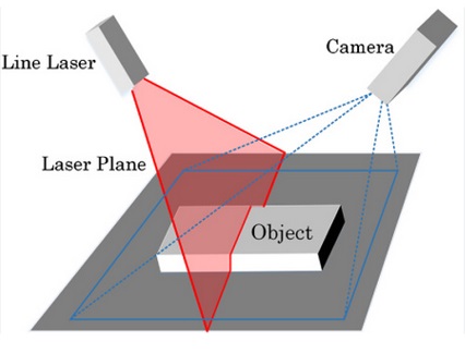
What considerations affect 3D triangulation laser profilers?
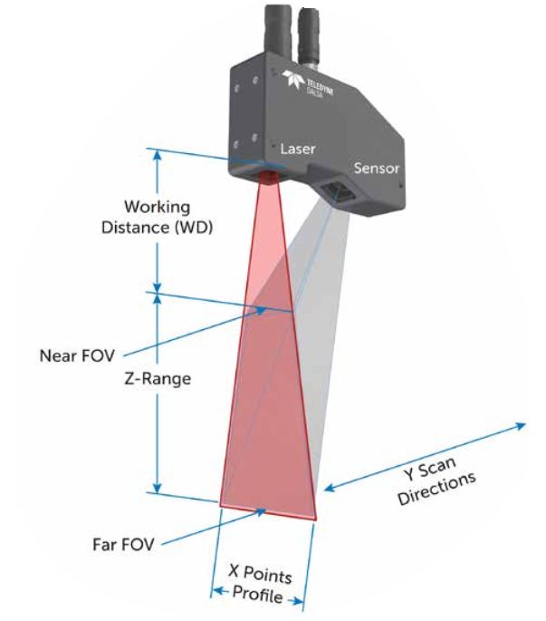
Data volume: With reference to Figure 2 below, the number of pixels per row (X) and the frequency of scans in the Y dimension, together with the number of Bytes expressed per pixel, determine the data volume. Ultimately you need what you need, and may purchase a line scanner with a wider or smaller field of view, or a faster or slower interface, or a more intense laser light, accordingly. Required resolution has a bearing on data volumes, too, and that’s the key consideration we’ll go into further below.
Resolution has a bearing on data volumes and application performance
Presumably it’s clear that application performance will require certain precision in resolution. In the Y dimension, how frequently do you need each successive data slice in order to track feature changes over time? In the Z dimension, how fine grained do you need to know of changes in object height? And in the X dimension, how many points must be captured at what resolution?
While you might be prepared to negotiate resolution tolerances as an engineering tradeoff on performance or cost or risk, generally speaking you’ve got certain resolutions you are aiming for if the technology and budget can achieve it.
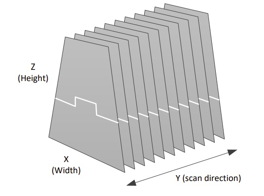
We’re warming up to the key point of this article – how line rate varies according to application features. Consider Figure 3 below, noting the trapezoidal shape for 3 respective fields of view, in correlation with working distance.
Trapezoid bottom width and required X dimension resolution
To drive this final point home, consider both Figure 2 and Figure 3. Figure 2, among other things, reminds us that we need to capture each successive scan from the Y dimension at precisely timed intervals. Otherwise how would we usefully track the changes in height in the Z dimension as the target moves down the conveyance?
That means that regardless of target height, each scan must always take exactly the same time as each other scan – it cannot vary. But per Figure 3, regardless of whether using a short, medium, or longer working distance, X pixels correlating to target values found high up in the trapezoidal FoV will yield a de facto higher resolution than the same X pixels lower down.
Suppose the top of the trapezoid is 50cm wide, and the bottom of the trapezoid is 100cm wide. For any given short span along a line in the X dimension, the real-space mapped into a sensor pixel will be 2x and long for targets sampled at the bottom of the FoV.
Since the required minimum resolution and precision is an applications requirement, the whole system must be configured for sufficient resolution when sampling at the bottom of the trapezoid. So one must purchase a system the covers the required resolution, and deploy it in such a way that the “worst case” sampling at the limits of the system are within the requirements. One must sample as many points as needed at the bottom of the FoV, and that impacts line scan rate.
Height of object matters too
Not only the position of the object in the FoV matters – but also the maximum height of any object whose Z dimension you need to detect. Let’s illustrate the point:
Consider item labeled Object in Figure 4. Your application’s object(s) may of course be shaped differently, but this generic object serves discussion purposes just fine. In this conceptual application, there’s a continuous conveyor belt (the dark grey surface) moving at continous speed in the Y dimension. Whenever no Object is present, i.e. the gaps between Object_N and Object_N+1, we expect the profiler to deliver a Z value of 0 for each pixel. But when an Object is present, we anticipate positive values corresponding to the height of the object. That’s the whole point of the 3D application.
Important note re. camera sensor in 2D
While the laser emits a flat line as it exits the projector, the reflection sensed inside the camera is two-dimensional. The camera sensor is a rectangular grid or array of pixels, typically in a CMOS chip, similar to that used in an area-scan camera. If one needs all the data from the sensor, the higher data volume takes longer to transfer than if one only needs a subset. If you know your application’s design well, you may be able to achieve optimized performance by avoiding the transfer of “empty” data.
Now let’s do a thought experiment where we re-imagine the Object towards two different extremes:
Extreme 1: Imagine the Object flattened down to a few sheets of paper in a tight stack, or perhaps the flap of a cardboard box.
Extreme 2: Imagine the Object is stretched up to the height of a full box, as high in the Z dimension as in the X dimension shown.
If the Object would never be higher than Extreme 1, the number of pixel rows in the camera sensor registering non-zero values will be just a few rows. Which can be read out quickly, not bothering to read out the unused rows. Yielding a relatively faster line rate.
But if the Object(s) will sometimes be at Extreme 2, many/most of the pixel rows in the camera sensor will register non-zero values, per the reflected laser line ranging up to the full height of the Object. Consequently more lines must be read-out from the camera sensor in order to build the laser profile.
1. The application must be designed to perform for the tallest anticipated Object, as well as the width of the Object in the X dimension and the speed of motion in the Y dimension.
Summary points regarding object height
2. All other things being equal, shorter objects, utilizing less camera sensor real estate, will support faster line rates, than taller object.
By careful planning for your FoV, knowing your timing constraints, and selecting your laser profiler model within it’s performance range, you can optimize your outcomes.

Also consider – interface capacity; exposure time
Just as with area scan cameras, output rates may be limited by any of interface limits, exposure duration, or data volumes.
Interface limits: Whether using GigE Vision, USB3 Vision, Camera Link HS – whatever – the interface standard, camera settings, cable, and PC adapter card together determine a maximum frame rate or line rate expressed in Gigabits per second (Gbps), typically. Your intended data volume is a function of exposure time and line rate or frame rate. Be sure to understand maximum practical throughput, choosing components accordingly.
Exposure duration: Even without readout timing considerations (overlapped readout together with start of next exposure – or completion of readout n before start of exposure n+1), if there are, say, 100 exposures per second, one cannot receive more than 100 datasets per second. Even if the camera is capable of faster rates.
That may seem obvious to experienced machine vision applications designers, but it needs mentioning for any new to this. Every application needs to achieve good contrast between the imaging subject and its background field. And if lighting and lensing are optimized, exposure time is the last variable to control. Ideally, lighting and lensing, together with the camera sensor, permit exposures brief enough so that exposure time meets application objectives.
But whether manually parameterized or under auto-exposure control, one has to do the math and/or the empirical testing to insure your achievable line rates aren’t exposure-limited.
Planning for your laser profiler application
Some months ago we wrote a blog which summarizes Teledyne DALSA’s Z-Trak line scan product families. Besides highlighting the characteristics of three distinct product families, we provided a worksheet to help users identify key applications requirements for line scanning. It’s worth offering that same worksheet again below. Consider printing the page or creating a copy of it in a spreadsheet, and fill in the values for your known or evolving application.
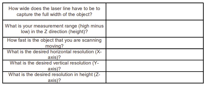
3D application key attributes
The moral of the story…
The takeaway is that the scan rate you’ll achieve for your application is more complex to determine than just reading a spec sheet about a laser profiler’s maximum performance. Your application configuration and constraints factor into overall performance.

1st Vision’s sales engineers have over 100 years of combined experience to assist in your camera and components selection. With a large portfolio of cameras, lenses, cables, NIC cards and industrial computers, we can provide a full vision solution!
About you: We want to hear from you! We’ve built our brand on our know-how and like to educate the marketplace on imaging technology topics… What would you like to hear about?… Drop a line to info@1stvision.com with what topics you’d like to know more about.