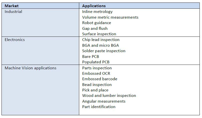
2D imaging is long-proven for diverse applications from bar code reading to surface inspection, presence-absence detection, etc. If you can solve your application goal in 2D, congratulations!
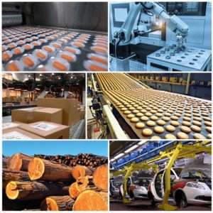
But some imaging applications are only well-solved in three dimensions. Examples include robotic pick and place, palletization, drones, security applications, and patient monitoring, to name a few.
For such applications, one must select or construct a system that creates a 3D model of the object(s). Time of Flight (ToF) cameras from Lucid Vision Labs is one way to achieve cost-effective 3D imaging for many situations.
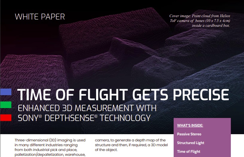
ToF is not about objects flying around in space! It’s about using the time of flight of light, to ascertain differences in object depth based upon measurable variances from light projected onto an object and the light reflected back to a sensor from that object. With sufficiently precise orientation to object features, a 3D “point cloud” of x,y,z coordinates can be generated, a digital representation of real-world objects. The point cloud is the essential data set enabling automated image processing, decisions, and actions.
| In this latest whitepaper we go into depth to learn: |
| 1. Types of 3D imaging systems |
| 2. Passive stereo systems |
| 3. Structured light systems |
| 4. Time of Flight systems |

Let’s briefly put ToF in context with other 3D imaging approaches:
Passive Stereo: Systems with cameras at a fixed distance apart, can triangulate, by matching features in both images, calculating the disparity from the midpoint. Or a robot-mounted single camera can take multiple images, as long as positional accuracy is sufficient to calibrate effectively.
Challenges limiting passive stereo approaches include:
Occlusion: when part of the object(s) cannot be seen by one of the cameras, features cannot be matched and depth cannot be calculated.
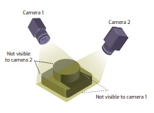
Few/faint features: If an object has few identifiable features, no matching correspondence pairs may be generated, also limiting essential depth calculations.
Structured Light: A clever response to the few/faint features challenge can be to project structured light patterns onto the surface. There are both active stereo systems and calibrated projector systems.
Active stereo systems are like two-camera passive stereo systems, enhanced by the (active) projection of optical patterns, such as laser speckles or grids, onto the otherwise feature-poor surfaces.
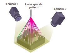
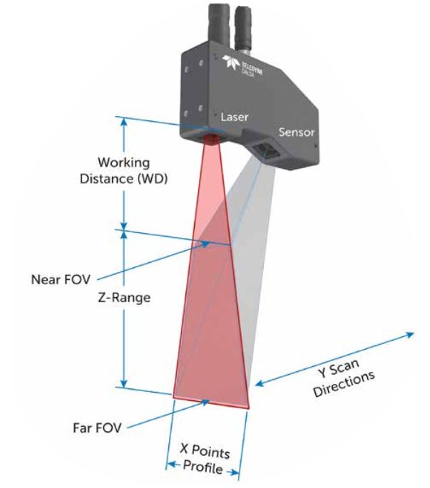
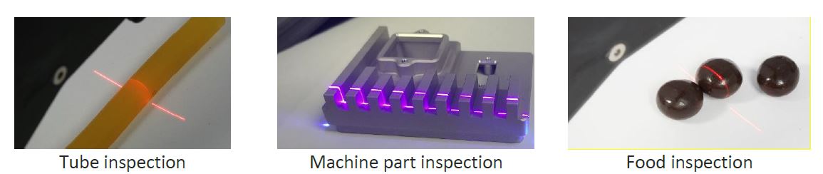
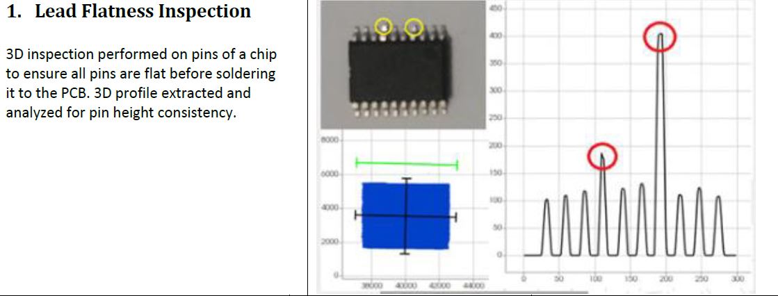
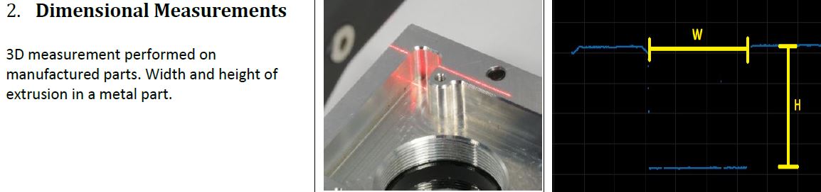
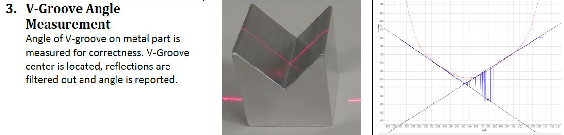
Calibrated projector systems use a single camera, together with calibrated projection patterns, to triangulate from the vertex at the projector lens. A laser line scanner is an example of such a system.
Besides custom systems, there are also pre-calibrated structured light systems available, which can provide low cost, highly accurate solutions.
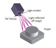
Time of Flight (ToF): While structured light can provide surface height resolutions better than 10μm, they are limited to short working distances. ToF can be ideal for or applications such as people monitoring, obstacle avoidance, and materials handling, operating at working distances of 0.5m – 5m and beyond, with depth resolution requirements to 1 – 5mm.
ToF systems measure the time it takes for light emitted from the device to reflect off objects in the scene and return to the sensor for each point of the image. Some ToF systems use pulse-modulation (Direct ToF). Others use continuous wave (CW) modulation, exploiting phase shift between emitted and reflected light waves to calculate distance.
The new Helios ToF 3D camera from LUCID Vision Labs, uses Sony Semiconductor’s DepthSense 3D technology. Download the whitepaper to learn of 4 key benefits of this camera, example applications, as well as its operating range and accuracy,
Have questions? Tell us more about your application and our sales engineer will contact you.

1st Vision’s sales engineers have an average of 20 years experience to assist in your camera selection. Representing the largest portfolio of industry leading brands in imaging components, we can help you design the optimal vision solution for your application.