OEM vision system builders often favor bare board cameras. They are typically very small and compact, attractively priced, and easy to fit into small spaces. Ideal for embedding into systems of your own design.
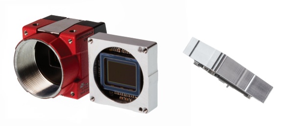
But sensor alignment can be challenging – enter the Alvium Frame
With a traditional housed camera, the sensor is typically aligned within the camera, to very precise tolerances. That insures that when the lens is mounted, the field of view is optimally transferred through the optics and onto the sensor, without introducing tip/tilt/focus losses.
Conversely, a board level camera is wonderfully compact, “just” a sensor and other electronics on a printed circuit board (PCB). But the integrator, often an OEM systems developer, is then left to his own skills aligning the PCB optical sensor and a corresponding lens. Even the most skilled mechanical engineers and systems builders can find optical alignment challenging. The tolerances are very fine, and besides optics knowledge and experience, it often takes special instrumentation and tooling to set, test, and tune the alignment. And then to insure the positioning remains stable relative to future vibrations once deployed in the target system.
Alvium Frame – sized like a board, aligned like a camera
Allied Vision’s innovation with the Alvium Frame was to recognize a market for something almost as small as a board level camera, yet sensor-aligned in a frame. And with helpful heat dissipation characteristics besides.

What happens if the sensor isn’t well-aligned?
Image quality can be negatively affected, by getting the geometry wrong. Optics is all about mapping the real world target through a lens and onto the 2D array of pixels in the sensor. So true orientation without rotation in the X or Y axis is preferred, as is proper depth in the Z axis, and avoidance of tip or tilt.
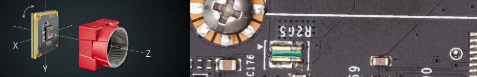
Consider the following illustration of sensor rotation off by just 1 degree. While the camera body and PCB board being imaged were squared to each other, for this illustration the sensor was rotated by 1 degree around the Z axis. It would not pass the alignment process in manufacturing production and quality control like this! Notice how the white line slopes down to the right, for this misaligned sensor.
Whether your application is PCB inspection, optometry, lasers, or any precision work, optical alignment matters.
Sensor tip/tilt impacts Modulation Transfer Function (MTF)
In our blogs, newsletters, Tech Briefs, and Knowledge Base, we periodically talk about the Modulation Transfer Function (MTF). It’s an important measure of lens performance. One typically seeks a lens that’s more than good enough for the task at hand, just as one’s camera, sensor, lighting, and data rates each have to be up to the job – a system is no better than its weakest link.
But a lens’ reported MTF is based on testing instances of the lens mounted on cameras with precisely aligned sensors. Any tip or tilt of the sensor away from the orthogonal plane might not greatly impact the central area of the image. But even a little tip or tilt, with the top leaning forward and the bottom backward, or the other way around, may lead to out-of-focus conditions away from the center of the sensor.
So even if the lens’ MTF is very good, an insufficiently aligned sensor can drag down imaging performance. Which is why it’s important to know the engineering tolerances of every optical component – or to trust your provider publishes and warranties their tolerances.
Alvium camera family – more than 200 variants
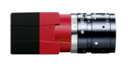
First came the “original” Alvium housed camera, of which there are more than 10 members in each of 1GigE and 5GigE interfaces. These compact cameras are attractively priced, with a range of sensors, and are feature-rich.
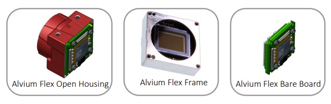
Variations are available through the Alvium Flex concept, with options for Open Housing, Flex Frame, and Bare Board. Designed for space-constrained applications, the Alvium Flex cameras offer USB and MIPI CSI-2 interfaces. Still feature-rich and with many sensor options, pricing in single or small quantities, or OEM volumes are available.
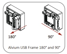
In another nod to OEM customers, the USB3 version of the Alvium Flex Frame has a choice of 2 interface positions, a rear exit (1800) or a side exit (90), as shown below:
So the Flex Frame offering fills a niche between housed vs. board level cameras. It’s close in size to board level, but with the alignment benefits of a housed camera.
So what are the alignment tolerances?
Let’s use the diagram and definition of terms below as a framework:
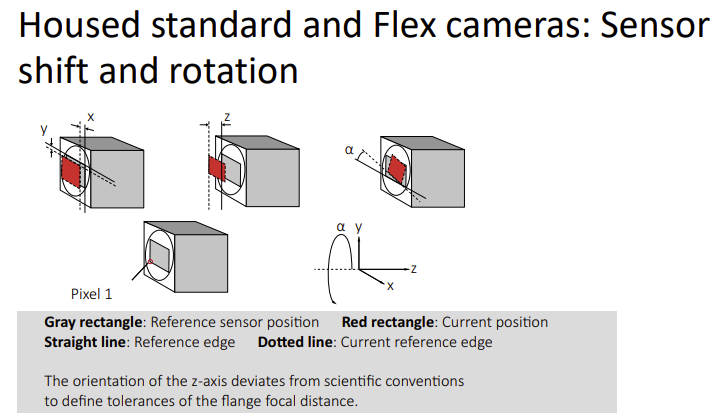
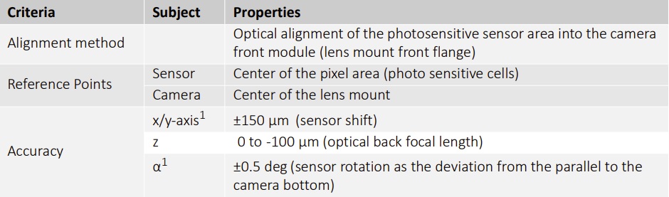
For housed-sensor Alvium models, Allied Vision asserts the following manufacturing accuracy for sensor positioning:
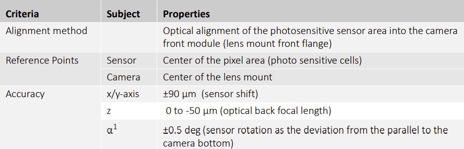
For Alvium Frame models, the table below shows sensor positioning tolerances:
Did I read that right? Frame model tolerances tighter than housed?
Exactly. Sensor shift in the x/y axis is +/- 90 µm in for Alvium Frame models fully 60 µm tighter tolerance than the +/- 150 µm for sensors in the housed Alvium models.
Likwise in the z axis, the optical back focal length is within 0 to -50 µm for the Alvium Frame models, while the Alvium housed models are factory calibrated to within 0 to -100 µm.
Other features of the Alvium Frame
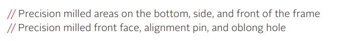
In addition to the optically important sensor alignment, the frame helps to dissipate heat via the metallic surface area, a benefit over a bare-board approach. The frame has 4 M2 screw holes for easy mounting. And there are two options to help you align the Alvium Frame within your own system:

1st Vision’s sales engineers have over 100 years of combined experience to assist in your camera and components selection. With a large portfolio of cameras, lenses, cables, NIC cards and industrial computers, we can provide a full vision solution!
About you: We want to hear from you! We’ve built our brand on our know-how and like to educate the marketplace on imaging technology topics… What would you like to hear about?… Drop a line to info@1stvision.com with what topics you’d like to know more about.