Event-based cameras outperform frame-based approaches for many applications. We provided insight to the event-based paradigm in a recent blog. Or download our whitepaper on event-based sensing.
In this piece, we focus on drone detection, a task at which event-based imaging excels. For full-impact, please view the following in full-screen mode using the “four corners” button.
As discussed in the event-based paradigm introductions links above, frame-based approaches would struggle to track a drone moving in a visually complex environment (above left), having to parse for drone shapes and orientations, occlusions, etc., even when most of the imagery is static.
Meanwhile, as seen in the event-based video (above right), the new paradigm only looks for “what’s changed”, which amounts to showing “what’s moving?”. For drone detection, as well as other perimeter intrusion applications, vibration monitoring, etc., that’s ideal.
1stVision represents Prophesee’s event-based sensors and cameras, built on neuromorphic engineering principles inspired by human vision. Call us at 978-474-0044 to learn more or request a quote.

For some applications, one only needs an event-based sensor – problem solved. For other applications, one might combine different imaging approaches. Consider the juxtaposition of three methods shown below:
The multimodal approach above is utilized in a proprietary system developed by EOPTIC, in which visible, polarization, and event-based sensors are integrated. For certain applications one may require the best of speed, detail, and situational awareness, for automated “confidence” and accuracy, for example.
Here’s another side-by-side video on drone detection and tracking:
The above-left video uses conventional frame-based imaging, where it’s pretty hard to see the drone until it rises above the trees. But the event-based approach used by Prophesee’s customer Neurobus, together with their own neuromorphic technologies, identifies the drone event amidst the trees – a level of early warning that could make all the difference.
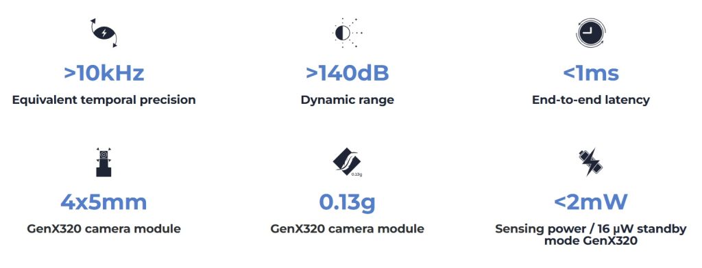
By the numbers:
Enough with the videos – looks compelling but can you quantify Prophesee event-based sensors for me please?
Ready to evaluate event-based vision in your application?
1stVision offers Prophesee Metavision® evaluation kits designed to help engineers and developers quickly assess event-based sensing for high-speed motion detection, drone tracking, robotics, and other dynamic vision applications. Each kit provides everything needed to get started with Prophesee’s Metavision technology, including hardware, software tools, and technical support from our experienced machine vision team. Request a quote to discuss kit availability, configuration options, and how we can help accelerate your proof-of-concept or system deployment.” – we can link that page with the kits.
Technical note: The GenX320 Starter kit for Raspberry Pi 5” utilizes the Sony IMX636 sensor, expressly designed for event-based sensing.
Kit or camera? You choose.
The kits described and linked above are ideal for those pursuing embedded designs. If you prefer a full camera – still very compact at less than 5cm per side – and you want a USB3 interface – see IDS uEye event-based cameras. You’ve got options.

1st Vision’s sales engineers have over 100 years of combined experience to assist in your camera and components selection. With a large portfolio of cameras, lenses, cables, NIC cards and industrial computers, we can provide a full vision solution!
About you: We want to hear from you! We’ve built our brand on our know-how and like to educate the marketplace on imaging technology topics… What would you like to hear about?… Drop a line to info@1stvision.com with what topics you’d like to know more about.