Black and white vs. color sensor? Monochrome or polychrome light frequencies? Visible or non-visible frequencies? Machine vision systems builders have a lot of choices – and options!
Let’s suppose you are working in the visible spectrum. You recall the rule of thumb to favor monochrome over color sensors when doing measurement applications – for same sized sensors.
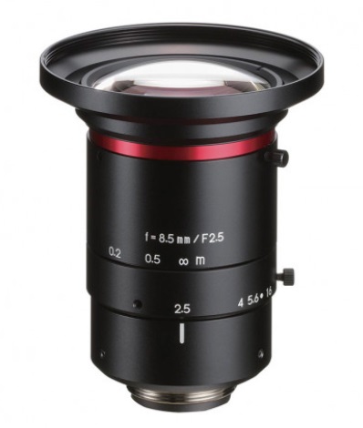
So you’ve got a monochrome sensor that’s responsive in the range 380 – 700 nm. You put a suitable lens on your camera matched to the resolution requirements and figure “How easy, I can just use white light!”. You might have sufficient ambient light. Or you need supplemental LED lighting and choose white, since your target and sensor appear fine in white light – why overthink it? – you think.
Think again – monochrome may be better
Polychromatic (white) light is comprised of all the colors of the ROYGBIV visible spectrum – red, orange, yellow, green, blue, indigo, and violet – including all the hues within each of those segments of the visible spectrum. We humans perceive it as simple white light, but glass lenses and CMOS sensor pixels see things a bit differently.
Chromatic aberration is not your friend
Unless you are building prisms intended to separate white light into its constituent color groups, you’d prefer a lens that performs “perfectly” to focus light from the image onto the sensor, without introducing any loss or distortion.
Lens performance in all its aspects is a worthwhile topic in its own right, but for purposes of this short article, let’s discuss chromatic aberration. The key point is that when light passes through a lens, it refracts (bends) differently in correlation with the wavelength. For “coarse” applications it may not be noticeable; but trace amounts of arsenic in one’s coffee might go unnoticed too – inquiring minds want to understand when it starts to matter.
Take a look at the following two-part illustration and subsequent remarks.
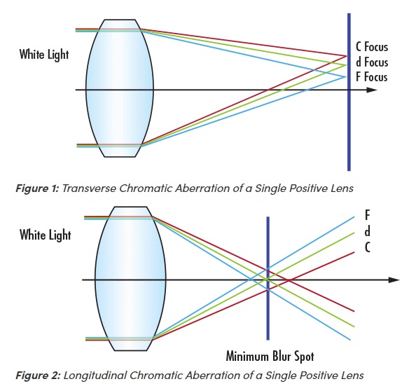
In the illustrations above:
- C denotes red light at 656 nm
- d denotes yellow light at 587 nm
- F denotes blue light at 486 nm
Figure 1, showing transverse chromatic aberration, shows us that differing refraction patterns by wavelength shift the focal point(s). If a given point on your imaged object reflect or emits light in two more more of the wavelengths, the focal point of one might land in a different sensor pixel than the other, creating blur and confusion on how to resolve the point. One wants the optical system to honor the real world geometry as closely as possible – we don’t want a scatter plot generated if a single point could be attained.
Figure 2 shows longitudinal chromatic aberration, which is another way of telling the same story. The minimum blur spot is the span between whatever outermost rays correspond to wavelengths occurring in a given imaging instance.
We could go deeper, beyond single lenses to compound lenses; dig into advanced optics and how lens designers try to mitigate for chromatic aberration (since some users indeed want or need polychromatic light). But that’s for another day. The point here is that chromatic aberration exists, and it’s best avoided if one can.
So what’s the solution?
The good news is that a very easy way to completely overcome chromatic aberration is to use a single monochromatic wavelength! If your target object reflects or emits a given wavelength, to which your sensor is responsive, the lens will refract the light from a given point very precisely, with no wavelength-induced shifts.
Making it real
The illustration below shows that certain materials reflect certain wavelengths. Utilize such known properties to generate contrast essential for machine vision applications.
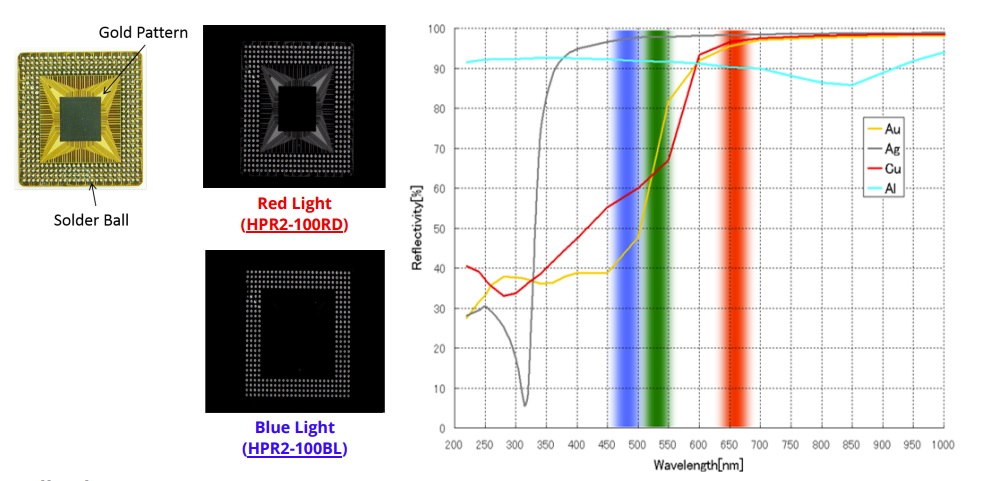
In the illustration we see that blue light reflects well from silver (Ag) but not from copper (Cu) nor gold (Ag). Whereas red light reflects well from all three elements. The moral of the story is to use a wavelength that’s matched to what your application is looking for.
Takeaway – in a nutshell
Per the carpenter’s guidance to “measure twice – cut once”, approach each new application thoughtfully to optimize outcomes:
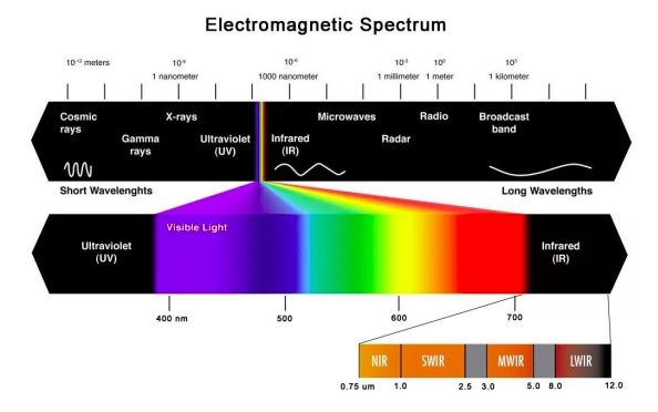
- Is the application best suited to visible or non-visible portions of the spectrum?
- If visible, is it best solved with a color sensor or a monochrome sensor (possibly using a specific color frequency)?
- Avoid chromatic aberration if possible by using monochromatic light
- Consider light sources and filters, in addition to the characteristics of your application’s substances and scenes

Additional resources you may find helpful from 1stVision’s knowledge base and blog articles: (in no particular order)
- CCS Illumination Wavelength Guide
- A Practical Guide to Machine Vision Lighting
- How machine vision filters create contrast

1st Vision’s sales engineers have over 100 years of combined experience to assist in your camera and components selection. With a large portfolio of cameras, lenses, cables, NIC cards and industrial computers, we can provide a full vision solution!
About you: We want to hear from you! We’ve built our brand on our know-how and like to educate the marketplace on imaging technology topics… What would you like to hear about?… Drop a line to info@1stvision.com with what topics you’d like to know more about.