All of us machine vision practitioners know a thing or two about camera lenses. Some of us are optical engineers. Others are self-taught through reading and experience. Others let their systems designers choose the lens.
Ever need a fast focus change?
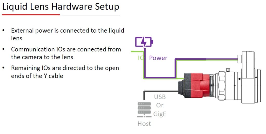
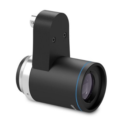
If your application does fine with a fixed focal lens, or a mechanically adjustable focus, that’s great. But some applications benefit from – or only become possible with – the ability to rapidly tune the focus. Enter liquid lenses, like Opto Engineering’s EL5MP and EL12MP.
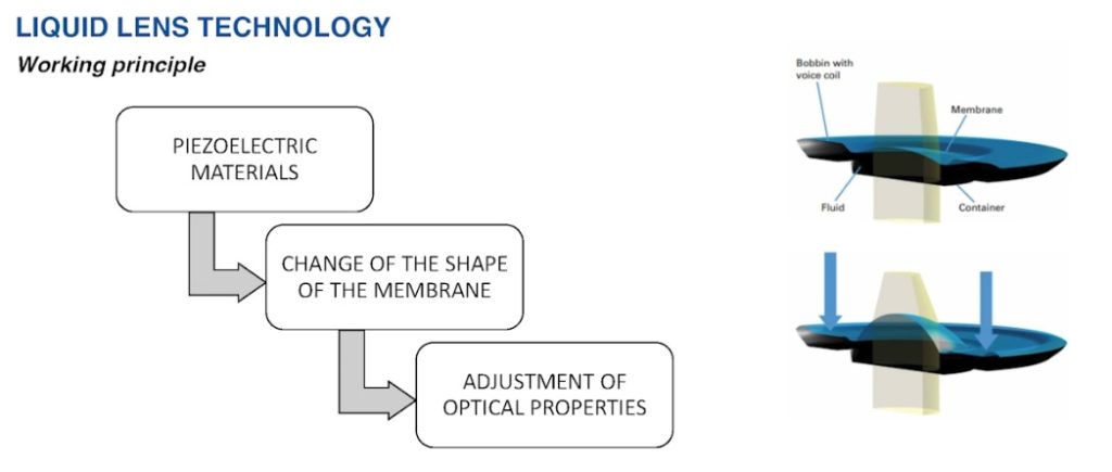
Liquid lenses – from theory to commercial availability
Leonhard Euler (Euler’s equations, anyone?) did groundbreaking work in fluid dynamics in the 1700s. In 1859 Thomas Sutton used a glass sphere filled with water to create a lens. So the concepts for liquid lenses aren’t new. But they’ve only been commercialized in the last 20 years. Here’s a short video (3 minutes) featuring an early leader in liquid lenses, with a nice overview of the key concepts:
From theory to practice – a 5MP and 12MP liquid lens series
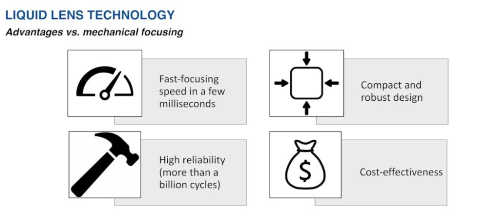
If you need fast focus (a few milliseconds) and high reliability (more than a billion cycle lifetime), Opto Engineering offers both a 5MP liquid lens series as well as a 12MP series. Each series provides several focal length options:
- 6mm for the 5MP series only
- 8mm for the 5MP series only
- 12mm for BOTH the 5MP and 12MP series
- 16mm for BOTH the 5MP and 12MP series
- 25mm for BOTH the 5MP and 12MP series
- 35mm for 12MP series only
Working distance coverage range
Across the two series, there are working distances on the near side from 60 – 200mm, depending on the specific model. At the far side the WD goes to infinity for each of the lenses. See the product comparison tables and data sheets at Opto Engineering EL5MP and EL12MP respectively.
More specs
The 5MP series is designed for sensors up to 2/3″. One exception: the 6mm focal length model is for sensors up to 1/1.8″.
The 12MP series is for sensors up to 1.1″.
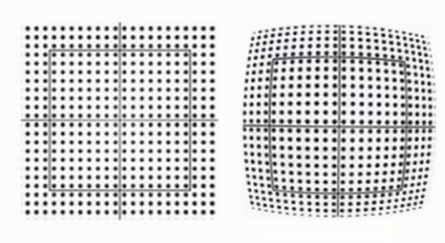
Low distortion is another advantage
What are the focus demands of your application?
Do you know your application’s focus requirements? Could you build a more effective application with faster focus? Reduce lens service and replacement intervals by switching from a mechanical to a liquid lens? Call us at 978-474-0044 to discuss options or get a quote.

Video presentation on Opto Engineering liquid lenses
Tradeshow presentation runs 14 minutes, if you want to do a deeper dive that way:
Note: Over the years, various operating principles for liquid lenses have been introduced.
#OptoEngineering

1st Vision’s sales engineers have over 100 years of combined experience to assist in your camera and components selection. With a large portfolio of cameras, lenses, cables, NIC cards and industrial computers, we can provide a full vision solution!
About you: We want to hear from you! We’ve built our brand on our know-how and like to educate the marketplace on imaging technology topics… What would you like to hear about?… Drop a line to info@1stvision.com with what topics you’d like to know more about.