TCSE series

High-resolution telecentric lenses for 4/3", APS-C, APS-H and full frame sensors

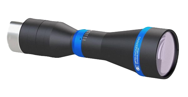
TCSE Telecentric Lens Overview

Opto Engineering TCSE telecentric lenses are designed for various large sensor formats (4/3", APS-C, APS-H ) and full frame sensors. Their very high-resolution and excellent optical performance delivers superb resolution with low distortion.

TCSE Series telecentric lenses are available in a variety of optical specifications and include lenses that are optimized for use in the near-infrared (NIR) wavelength range.

The TCSE telecentric lenses feature a robust design, high-accuracy and high-precision that makes them suitable for many machine vision applications including inspection, aerospace, automotive, and medical applications. Long working distances provide additional space for lighting, and industrial tools such as robotic arms.

TCSE Telecentric Lens Features

  1. Wide image circle for sensors up to 45.7 mm
  2. High resolution with low distortion
  3. High-accuracy and high-precision
  4. Long working distance
  5. Robust design ideal for industrial environments
  Main optical specifications Object field of view Advanced optical specifications Mechanical specifications Datasheet Get
Quote
Part
number
Additional
notes*
Magnification Image
circle
diameter
Max
sensor
size
4/3"
IMX367
CHR70M CMV50000 Working
distance
Wavelength
range
Working
ƒ/N
Telecentricity
typical
(max)
Distortion
typical
(max)
Depth
of
field
Mount Length Front
diameter
         15.29 x 15.30 31.00 x 21.99 36.43 x 27.62               
    (x) (mm)   (mm × mm) (mm × mm) (mm × mm) (mm) (nm)   (deg) (%) (mm)   (mm) (mm)
                1   2 3 4 5 7 9  
TCSE5M065-J 0.366 23.9 4/3" 41.78 x 41.80 ø = 60.08 ø = 65.30 189 440-640 8-32 <0.06 (0.08) <0.08 (0.10) 3.1M42x1 FD 12 192 88 TCSE5M065-J datasheet
TCSE10M056-F   0.46 28.4 APS-C 33.24 x 33.26 ø = 47.81 ø = 60.04 160 460-630 11-27 <0.06 (0.08) <0.06 (0.08)2.7F23082 TCSE10M056-F datasheet
TCSE16M048-I 0.8 45.7FF 19.11 x 19.13 38.75 x 27.49 45.54 x 34.52 240460-640 8-32 <0.08 (0.10) <0.10 (0.15)0.7M58x0.75 FD 11.48355100 TCSE16M048-I datasheet
TCSE16M036-I 0.9245.7 FF16.62 x 16.63 33.70 x 23.9039.60 x 30.02 240460-6408-16 <0.08 (0.10)<0.08 (0.10)0.5M58x0.75 FD 11.48351.480 TCSE16M036-I datasheet
TCSE16M028VISNIR-Fa1.537.42.4"10.19 x 10.2020.67 x 14.66ø = 18.41 211450-96016-32 <0.06 (0.08)<0.06 (0.08)0.4F356.160 TCSE16M028VISNIR-F datasheet
TCSE16M024-Fb 1.637.42.4" 9.56 x 9.5619.38 x 13.74 ø = 17.26180 400-70010-32 <0.06 (0.08)<0.06 (0.08)0.2F37061 TCSE16M024-F datasheet
TCSE16M024NIR-F 1.637.42.4" 9.56 x 9.5619.38 x 13.74 ø = 17.26163 760-82510-32 <0.08 (0.10)<0.08 (0.10)0.2F230.261 TCSE16M024NIR-F datasheet
TCSE10M009-Jb2.75 28.2APS-C5.56 x 5.56 ø = 8.00ø = 10.04 178400-70011.5 <0.06 (0.08)<0.06 (0.08) 0.1M42x1 FD 12381.561 TCSE10M009-J datasheet

Notes

  1. Working distance: distance between the front end of the mechanics and the object. Set this distance within ±3% of the nominal value for maximum resolution and minimum distortion.
  2. Working f-number (wf/N): the real f-number of a lens in operating conditions.
  3. Maximum angle between chief rays and optical axis on the object side. Typical (average production) values and maximum (guaranteed) values are listed.
  4. Percent deviation of the real image compared to an ideal, undistorted image. Typical (average production) values and maximum (guaranteed) values are listed.
  5. At the borders of the field depth the image can be still used for measurement but, to get a very sharp image, only half of the nominal field depth should be considered. Pixel size used for calculation is 3.45 µm.
  6. Object side, calculated with the Rayleigh criterion with λ= 520 nm
  7. FD stands for Flange Distance (in mm), defined as the distance from the mounting flange to the camera detector plane.
  8. Indicates the availability of an integrated camera phase adjustment feature.
  9. Measured from the front end of the mechanics to the camera flange.

*Additional Notes

a. This lens works in VIS and IR wavelength range separately, changing working distance between the two configurations

b. This lens works only with a 50 mm cube beamsplitter in front of the objective

TC 23 004
TC 23 007
TC 23 009
TC 23 012
TC 12 016
TC 23 016
TC 12 024
TC 23 024
TC 13 036
TC 12 036
TC 23 036
TC 13 048
TC 12 048
TC 23 048
TC 12 056
TC 23 056
TC 13 064
TC 12 064
TC 23 064
TC 23 072
TC 13 080
TC 12 080
TC 23 080
TC 23 085
TC 13 096
TC 12 096
TC 23 096
TC 23 110
TC 12 120
TC 23 120
TC 23 130
TC 12 144
TC 23 144
TC 23 172
TC 12 192
TC 23 192
TC 23 200
TC 23 240

Product images

Opto Engineering TCSE5M065-J telecentric lens
TCSE5M065-J telecentric lens

Opto Engineering TCSE10M056-F telecentric lens
TCSE10M056-F telecentric lens

Opto Engineering TCSE16M048-I telecentric lens
TCSE16M048-I telecentric lens

Opto Engineering TCSE16M036-I telecentric lens
TCSE16M036-I telecentric lens

Opto Engineering TCSE16M028VISNIR-F telecentric lens
TCSE16M028VISNIR-F telecentric lens

Opto Engineering TCSE10M056-F telecentric lens
TCSE16M024-F telecentric lens

Opto Engineering TCSE16M024NIR-F telecentric lens
TCSE16M024NIR-F telecentric lens

Opto Engineering TCSE10M009-J telecentric lens
TCSE10M009-J telecentric lens

Technical documents

Product user guide PDF
Back focal length adjustment PDF

Please contact us if you have questions or need more information.