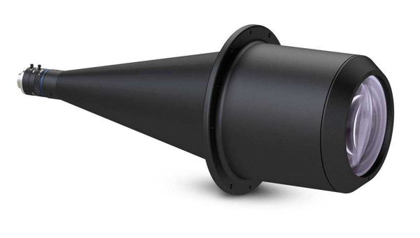
 Opto Engineering PC 360° pericentric lenses capture the top and lateral sides of an image in perfect focus in one image using a single camera. This design alleviates the need for multiple cameras and image matching software that's required by "multi-point" imaging systems. PC pericentric 360° lenses are designed to work with 1/3", 1/2" and 2/3" detectors to inspect objects up to 60 mm in diameter.
Opto Engineering 360° lenses are high quality lenses with superb optical performance. They are specifically designed for 360° inspection of objects, and are widely-used in machine vision applications such as automotive, pharmaceutical, and beverage inspection. There are many 360° lenses and options. Our Sales Engineers can provide expert advice and guidance on selecting the right lens for your machine vision 360° imaging application. Please contact us if you would like more information.
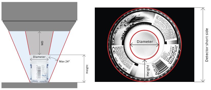
An object’s size and height determines the optimal working distance and recommended F-number. This Field of view selection chart shows the combinations of object diameters, height, working distance, recommended F-number, and "r" parameter (a ratio between the side view height and the detector short size.
r(%) = (Side view height px / Detector short side px) * 100
