IDS peak 2.17.1 / uEye+ firmware 3.70
IDS Peak comfortSDK, genericSDK, IPL, and AFL developer manuals are external documents. Please contact us if you need them.
IDS industrial cameras are equipped with area scan sensors, which means that the sensors have a matrix of rows and columns of pixels. In specific applications, however, it may be necessary to read out and transmit only a single sensor line instead of the entire sensor area. For this purpose, so-called line scan cameras are often used, whose sensors only have one row of pixels.This row of pixels is read out at very high speeds in kilohertz range (kHz). Through to the “line scan mode”, an IDS area scan camera can also be used for a variety of simple applications in web inspection, for example for textiles, paper, rims or silicon wafers. However, it is also possible to capture round or curved objects. The simple setup and small system costs provide a cost-effective alternative to an original line scan camera. The big advantage of an area scan camera with line scan mode is an easy setup of the desired image scene in basic area scan mode and the possibility to re-adjust it at later time.
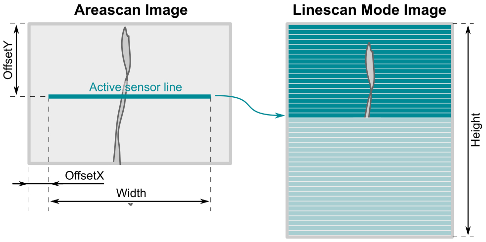
The line scan preset optimizes the camera settings to capture a single sensor line in the center of the image (configurable) to continuously scan moving objects at a high line-frequency. With a color sensor, at least 2 lines must be captured for calculating the color information. The captured lines are merged in the camera to create a two-dimensional image of up to 8000 pixels in height and transmitted to the PC as a complete image. The image width (Width) and image height (Height) can be set via parameters. Depending on the camera model, you can also set the number of lines via SensorHeight.
Once you have defined the active line position and the image geometry, use the image and line triggers to adjust the acquisition time and speed to the object movement of your application. In line scan mode, the line trigger allows you to start the acquisition of the active line at regular intervals via encoders, even with varying object speeds. So you can avoid distorted representations of scanned objects.
Configuration

Fig. 78: Line scan mode
Setting the image geometry for line scan mode
•Width: Width of the sensor line to be read out (monochrome models: 1 line, color models: 2 lines)
•OffsetX: Offset of the sensor line from the left frame border
•OffsetY: Offset of the sensor line from the top frame border
•Height: Height of the merged image that is transmitted. The sensor rows are filled from top to bottom.
•SensorHeight For some camera models, you can use SensorHeight to set an individual line height in line scan mode.
use case |
Description |
Frame trigger |
Line trigger |
|---|---|---|---|
Printed web material |
Frames can be triggered, for example, by a light barrier. The line signal is controlled by an encoder. |
Hardware trigger |
Hardware trigger |
Non-printed web material |
There is no frame sync signal. The line signal is controlled by an encoder. |
Freerun |
Hardware trigger |
Printed web material without speed fluctuations |
Frames can be triggered, for example, by a light barrier. There is no signal that triggers a line. The starting and braking behavior of the web cannot be compensated. |
Hardware trigger |
Freerun |
Unprinted web material without speed fluctuations |
There is neither a frame sync signal nor a signal that triggers the lines. The starting and braking behavior of the web cannot be compensated. |
Freerun |
Freerun |
|
Camera inputs without optocouplers are more suitable for line triggering than inputs with optocouplers. Although the external circuit is not galvanically isolated (electrically isolated) for inputs without optocouplers, these inputs provide a faster response, which is an advantage at high line frequencies. |
Example based on the "Printed web material" use case
Load the line scan presets via UserSetSelector.
UserSetSelector = Linescan
Execute >> UserSetLoad
Set the image size.
OffsetY = 700
Height = 2000
Width = 1600
OffsetX = 240
With "Line0" as the TriggerSource, a light barrier can start image acquisition as an external hardware trigger source. The exposure of the active sensor line ("700") is started synchronously to the web speed via "Line2", controlled by a encoder.
TriggerSelector = Framestart
TriggerSource = Line0
TriggerActiviation = RisingEdge
TriggerMode = On
TriggerSelector = LineStart
TriggerSource = Line2
TriggerActiviation = RisingEdge
TriggerMode = On
Use AcquisitionStart to enable the system to receive trigger signals.
Execute >> AcquisitionStart
Notes on line scan mode
•When AcquisitionStop is called, image acquisition is stopped at the end of the current image in order to deliver a complete image. However, when AcquisitionStop cannot be executed within 2 seconds in line scan mode, the image is aborted and delivered as incomplete.
•When triggering lines, you need high timeout values depending on the speed and size of the image.
Additional information
Camera basics |
|
|---|---|
Camera feature reference |
|
IDS peak Topics |
|
TechTip |
|
Vision Channel |
Watch our how-to video to learn how to use a IDS area scan camera as a line scan camera: https://en.ids-imaging.com/visionchannel-media-details/items/how-to-linescan-with-2d-industrial-cameras.html |
