IDS Software Suite 4.96.1
This tab provides parameters for setting miscellaneous functions for your uEye camera.
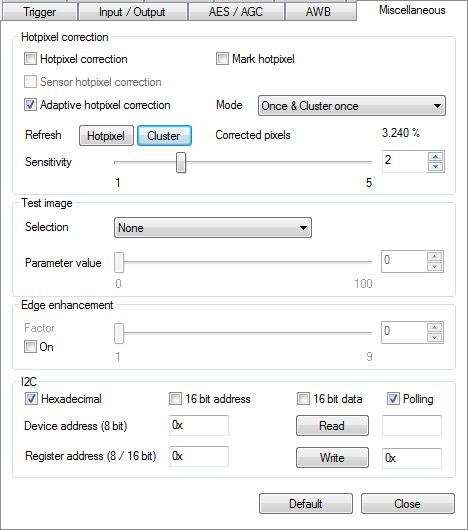
Fig. 131: uEye properties - Miscellaneous
|
Notes on sensor hotpixel correction on the UI-124x/UI-324x/UI-524x and UI-125x/UI-325x/UI-525x If sensor hot pixel correction and Multi AOI are enabled, the sensor displays a four pixel wide black line between the AOIs. |
Hotpixel correction
This function corrects the sensor hot pixels specified in the non-volatile camera memory.
•Mark hotpixel
If you select this check box, the hot pixel positions stored in the camera are graphically represented in the image.
•Hotpixel correction
Select this check box if you want to enable a software-based hot pixel correction.
•Sensor hotpixel correction
Enables the sensor's internal hot pixel correction for some models.
•Adaptive hot pixel correction
Enables the adaptive hot pixel correction. The adaptive hot pixel correction can determine hot pixels dynamically and correct them adaptively in the current image. Thus, hot pixels can be corrected better which, for example, result from an increased temperature. In addition, the adaptive hot pixel correction can be executed directly in live operation, thus permitting the best possible optimization on the application conditions.
|
Note on adaptive hot pixel correction •Adaptive hot pixel correction can be used in combintaion with subsampling, binning or scaler. •Currently, adaptive hot pixel correction can only be used with software color formats or RAW color formats. |
•Mode
The following modes are distinguished for the adaptive hot pixel correction:
o"Detect once": The hot pixels are determined once and stored in a list. The adaptive hot pixel correction works with this list. This mode is suitable for all applications with static light conditions which do not require dynamic adaptation.
o"Detect dynamically": The hot pixel list is dynamically determined for each image. So, this allows a better response for changing light conditions. In this mode, the full frame rate may not be achieved.
o"Once & Cluster once": The hot pixels and the hot pixel clusters are determined once and stored in the hot pixel list as well as in the cluster list. The adaptive hot pixel correction works with both lists.
o"Dynamically & Cluster once": The hot pixel list is dynamically determined for each image. The hot pixel clusters are determined once and stored in the cluster list.
o"Dynamically & Cluster dynamically": Both the hot pixel list and the cluster list are dynamically determined for each image. So, this allows a better response for changing light conditions. In this mode, the full frame rate may not be achieved.
•Refresh
o"Hotpixel": Resets the hot pixel list and determines it with the next image. This command has only an effect in combination with the "Detect once". setting.
o"Cluster": Resets the hot pixel and cluster list and determines both lists with the next image. This command has only an effect in combination with the "Cluster once". setting.
•Sensitivity
Sets the value for the sensitivity of the adaptive hot pixel correction: 1 (lowest sensitivity) … 5 (maximum sensitivity)
•Corrected pixels
Returns the percentage of corrected hot pixels in the last image. If the hot pixels are determined once the value will not change until the next determination. For dynamic determination, the value may change with each image.
|
Hint for adaptive hot pixel correction If the hot pixels are determined once, you should deactivate LUT, gamma, and RGB gains for detection. For dynamic detection, the use of LUT, gamma, and RGB gains may cause too many hot pixels to be determined and corrected. This can cause a high CPU load. |
The camera transmits a selectable test image that you can use for testing the data transmission. You can choose from different types of test images, depending on the camera type.
•Selection
Some of the test images (e.g. Black image and White image) are created by the sensor and are available in both, USB-based and GigE-based uEye models.
Test images marked (RAW) are only properly displayed in raw Bayer mode (see Color).
 Black image |
 White image |
 Horizontal bars (raw data) |
 Vertical bars (raw data) |
 Vertical grayscale |
 Horizontal grayscale |
 Chess pattern |
 Gray wedge |
 Diagonal grayscale |
 Animated line |
 Animated gray wedge |
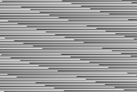 Alternate pattern |
 Color bars |
 Color bars 2 |
 Color bars with grayscale |
 Colored wedge |
 Animated colored wedge |
 Variable red part |
 Variable green part |
 Variable blue part |
 Variable gray part |
Coldpixel grid |
Hotpixel grid |
 Shading Image |
•Parameter value
You can adjust the appearance of some of the test images with the "Parameter value" slider.
|
Notes on test images •Manually changing the pixel clock will disable the test image mode. •Animated test images are ideal for testing recorded sequences. •With some sensors, the sensor gain setting has an influence on the test image. •For USB cameras, you can use a white test image to check the camera's maximum load on the USB bus. Due to the transmission process, completely white camera images require somewhat more bandwidth on the USB bus than completely black images. •To turn on hotpixel correction does not make sense for a test image. •The test images are transferred with a bit depth of 8 bit. •If you have set a test image inclusive parameter, you must first reset the parameter before you can select another test image. |
Edge enhancement
•This function activates a software filter that emphasizes the edges in the image.
Enabling the edge enhancement function increases the CPU load during image capture.
I2C
This function is available on a number of uEye board level cameras. It allows reading and writing data via the TWI (Two Wire Interface).
|
I2C functions are only supported by the following PCB versions: •uEye LE USB 3.1 Gen 1 •USB 3 uEye LE •USB uEye LE •GigE uEye LE. |
•Hexadecimal
Select this check box if you want to enter addresses and data in hexadecimal format. If the check box is disabled, the data needs to be entered in binary format.
•16 bit address
Select this check box to send addresses at 16 bit width.
•16 bit data
Select this check box to send data at 16 bit width.
•Polling
By default, it is polled when the data is actually written to register.
•Device address (8 bit)
Address of the I2C device to be accessed.
•Register address (8/16 bit)
Address of the register to be read or written.
•Read
Data to be read from the register.
•Write
Data to be written to the register.
Resetting the parameters
Click on the "Default" button to reset all parameters to the model-specific defaults.
See also: •Basics: Hot pixels Programming: •Hot pixel: is_HotPixel() •Edge enhancement: is_EdgeEnhancement() •Test image: is_SetSensorTestImage() •I2C: is_ReadI2C() •I2C: is_WriteI2C() |
